Max ER-2700 User manual


- 1 -
CONTENTS
BEFORE USE .....................................................................................................................2
SAFETY INSTRUCTIONS.........................................................................................2
ACCESSORIES .........................................................................................................3
MAIN FEATURES......................................................................................................4
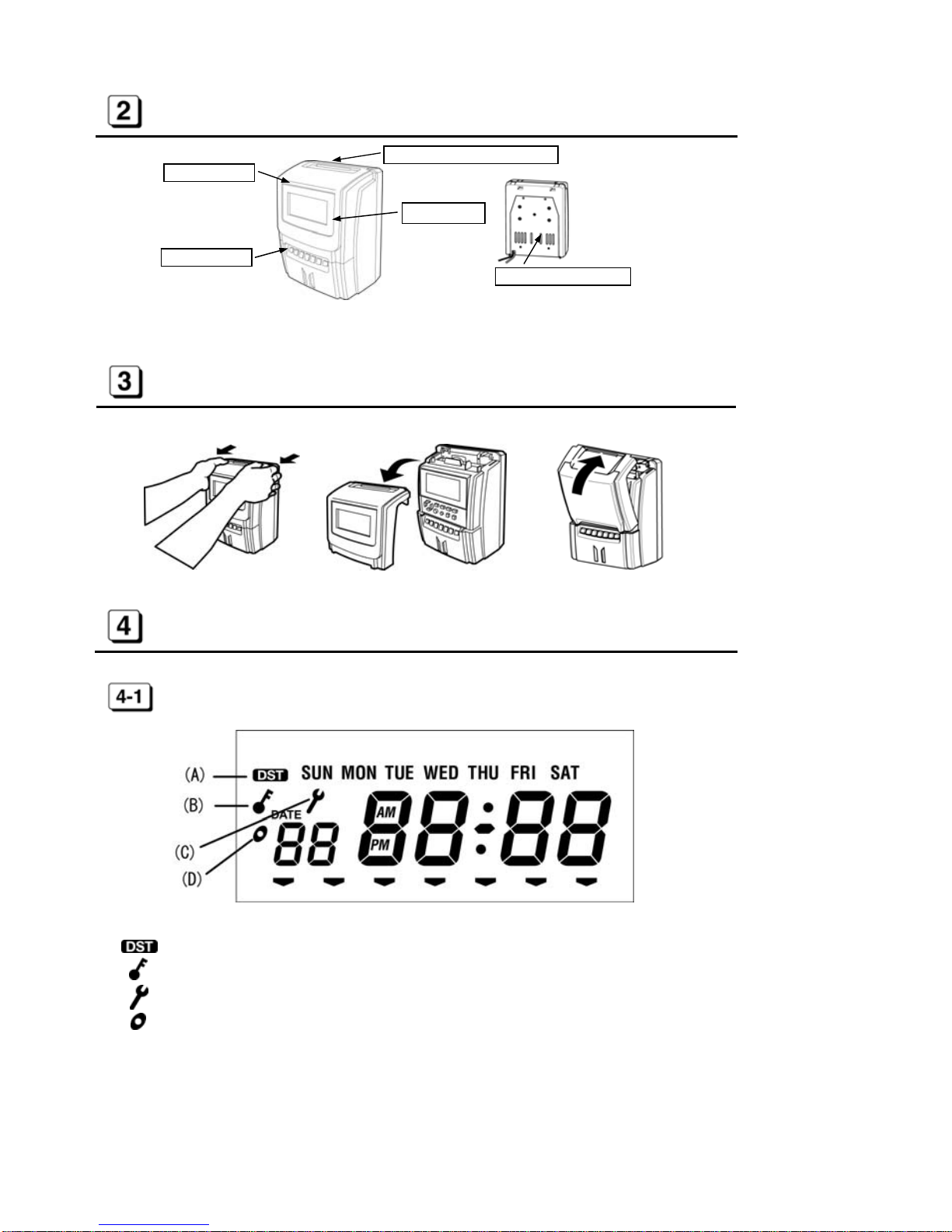
PARTS DESCRIPTIONS.....................................................................................................5
HOW TO OPEN AND CLOSE FRONT COVER.................................................................5
DISPLAY AND KEYBOARD...............................................................................................5
DISPLAY LAYOUT.....................................................................................................5
KEYBOARD LAYOUT...............................................................................................6
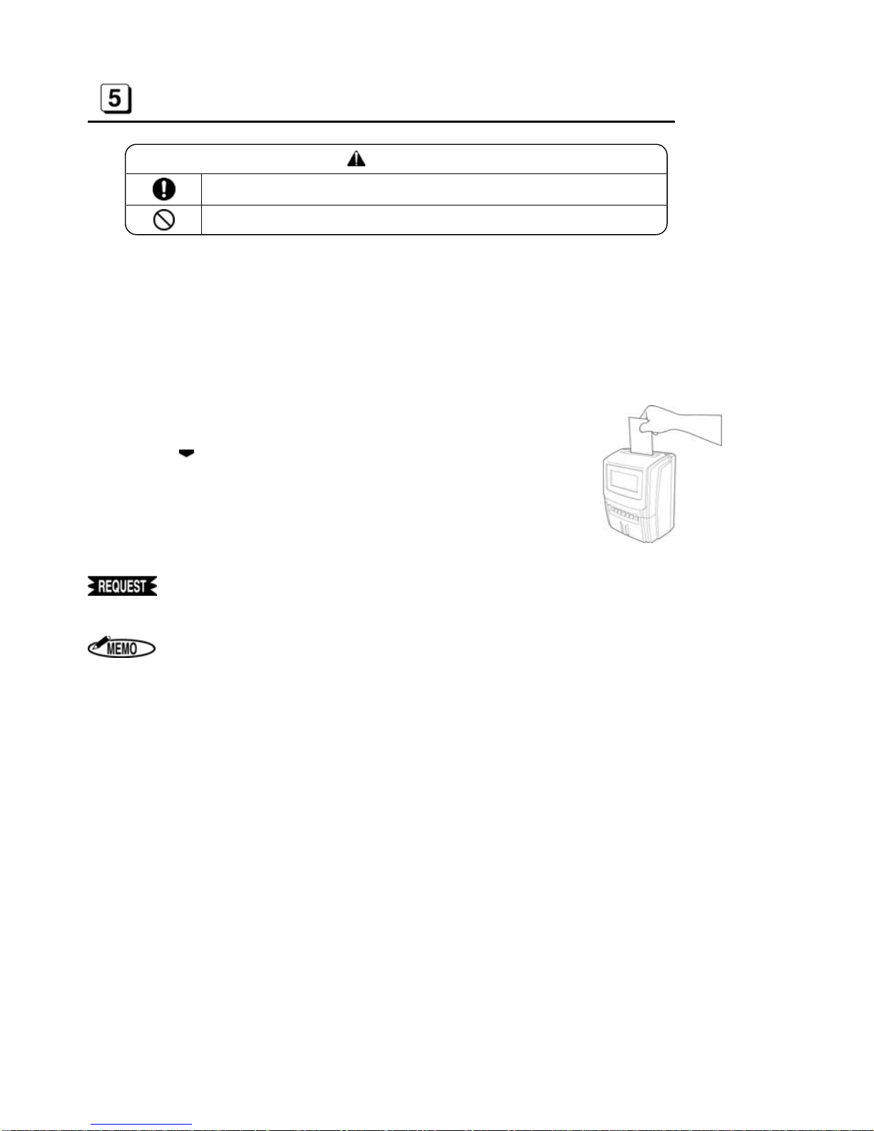
HOW TO OPERATE............................................................................................................7
HOW TO SET UP................................................................................................................8
SETTING OR CHANGING DATA..............................................................................8
BASIC OPERATION OF SETTING OR CHANGING DATA.....................................8
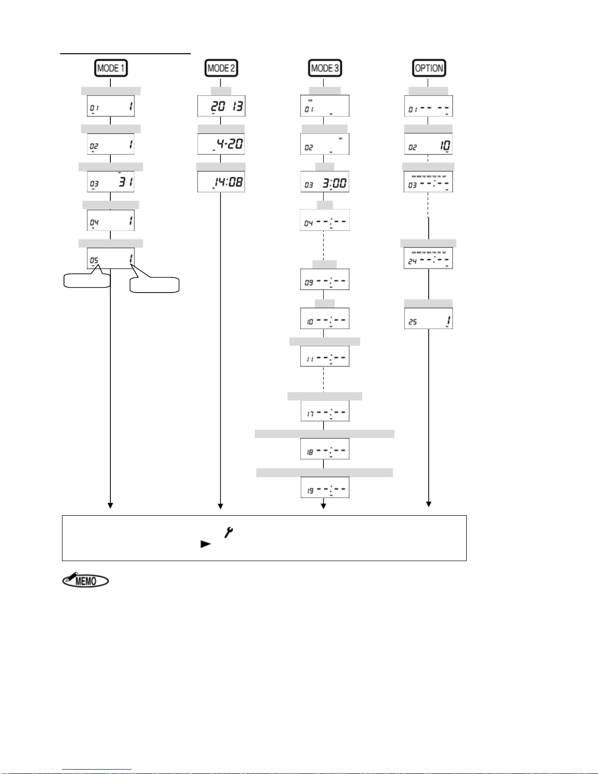
SETTING MODE 1 ............................................................................................................10
MACHINE MODE 1 (CODE 01)...............................................................................10
MACHINE MODE 2 (CODE 02)...............................................................................10
PAY CLOSING DATE (CODE 03) ...........................................................................11
60 OR 100 SCALE (CODE 04)................................................................................11
DAILY TOTAL HOURS (CODE 05).........................................................................12
SETTING MODE 2 (YEAR, MONTH, DATE, HOUR, AND MINUTE) ..............................14
SETTING MODE 3 ............................................................................................................14
HOLIDAY (CODE 01)...............................................................................................14
SPECIAL DAY (CODE 02) ......................................................................................15
LINE SHIFT TIME, IN/OUT AND OVERTIME WORKING (CODE 03 to 10, # FOR SPECIAL
DAY: CODE 11 to 17)..............................................................................................15
DAYLIGHT SAVING TIME (CODE 18 to 19)..................................................................16
SETTING OPTION ............................................................................................................18
CONNECTION TO EXTERNAL TIME SIGNAL ..............................................................21
REPLACING INK RIBBON CASSETTE...........................................................................22
WALL MOUNTING AND LAID-DOWN POSITION INSTALLATION ...............................23
ERROR CODES................................................................................................................24
CAUTION CODE...............................................................................................................24
TROUBLE SHOOTING.....................................................................................................25
SPECIFICATIONS.............................................................................................................25

- 2 -
BEFORE USE
SAFETY INSTRUCTIONS
■INDICATIONS
This instruction manual and the product use various indications to help you use this instrument safely and properly.
The following describes those indications.
WARNING: Negligence could lead to serious injury or death.
CAUTION: Negligence could lead to an injury, damage of your property, or
cause loss of created data.
Describes operations that may cause damage to the instrument and require a re-
pair, or operations that require resetting the machine, etc., to restore the condition
of the instrument.
Describes the points of operation and tips.
Describes a functional precaution.
■SYMBOLS
Denotes “What you should be aware of.”
Denotes “What you must not do.” An indication in or near this symbol shows a
specific prohibition.
Denotes “What you must do.” An indication in this symbol shows a specific in-
struction.
WARNING
This is a class A product. In a domestic environment this product may cause radio in-
terference in which case the user may be required to take adequate measures.
Clean a power cord plug regularly. Dust on the plug could cause a fire.
Obtain power directly from a single plug socket. Avoid connecting many wires to one
plug socket. It could lead to a fire.
Do not connect/disconnect a power plug with a wet hand. It could cause an electric
shock.
●Do not operate the instrument, if it is out of order. If it is operated in an out-of-order
state, such as it is smoking, emitting an abnormal sound, or smelling funny, it could
cause a fire or electric shock. Disconnect a power plug immediately from a socket
and contact your dealer/distributor for a repair.
●Disconnect a power plug before connecting to an external time signal.
A lithium battery is used inside for memory backup. Never replace the lithium battery
by yourself. Contact your dealer/distributor for replacement.
CAUTION
Data stored in the internal memory cannot be stored permanently. We will not be re-
sponsible for damages and lost profits caused by loss of data attributed to battery con-
sumption, trouble, repair, and so on.

- 3 -
Never disassemble or modify this instrument. It could cause a fire, electric shock, or
other problems.
●Do not insert foreign substances such as fingers, pens, wire, or paper into this in-
strument. It could damage the instrument or cause a fire.
●Use correct supply voltage. Other voltage level could damage the instrument.
●Do not splash water or chemicals on the instrument. If water gets inside the in-
strument, disconnect a power plug immediately from a plug socket and contact your
dealer/distributor for a repair. It could damage the instrument or cause a fire or
electric shock.
● Do not put paper or cloth on the instrument. It could cause a fire.
●Do not place any heavy material on a power cord. It could cause damage or a fire.
●Never touch a printer head. It is very hot just after printing and you could get
burned. Also, dirt on your hand could cause trouble to the printer head.
●When the instrument is not going to be operated for a long period of time, be sure to
disconnect a power cord from a power socket for your safety.
●When disconnecting a power cord, be sure to hold a power plug. Do not pull on the
power cord, or the cord could be broken and cause a fire or electric shock.
ACCESSORIES
This instrument comes with the following accessories. Confirm that they are included before using the machine.
1. Instruction manual 2. Screws for wall mounting
INSTRUCTIONM ANUAL
☆Before using this instrument, study this manual to ensure
safety warning and instructions. Keep thisinstructi on manual
with the instrument for futu rereference.
2700
: 1 booklet : 4-pcs.
◆Do not drop or hit the instrument.
◆Install this instrument away from the following places:
1.Any place that is not level or that is subject to vibration.
2. Any place that has dust or high humidity. Keep beverages and liquid
containers away from this instrument.
3.Any place that the temperature goes below 0 /32 or over 40 /104 .
4. Any place that catches direct sunlight or is located close to a heat source.
◆Do not insert cards or paper other than the specified time cards for this in-
strument. Do not use time cards that are bent or torn.
◆Be sure to use a dry cloth for cleaning. Do not use solvents (alcohol, ben-
zene, thinner, etc.) or a damp cloth.
◆Do not re-ink cartridge. Replace with ink ribbon cassetteER-IR102E.
◆Do not hang this instrument on a wall using anything other than the included plate for wall mounting.
◆The socket-outlet shall be installed near the equipment and shall be easily accessible.
◆A 30-minute break is required after continuous printing 15 minutes.

- 4 -
MAIN FEATURES
1. Up to 6 columns (Up to 4 columns when using the Daily Total Hours function).
2. Two-color printing (Black/Red).
3. Printing Daily Total Hours calculation and Accumulation of Daily Total Hours.
4. Can select regular working time or overtime as Daily Total Hours.
5. Setting up to 22 times for external time signal.
6. Setting another program for Special day.
7. Printing regular minutes (1/60) or 1/100th of an hour.
8. Can select one of three styles from the following table.
Capacity of employees Setting program
150 employees Using Next Day Overtime function
(Without Daily Total Hours function)
130 employees Using Daily Total Hours function
(Without Next Day Overtime function)
60 employees Using Daily Total Hours function and Next
Day Overtime function
9. Printing “Late-in: ,” “Early-out: ,” “Overtime: ” and “Next Day Overtime: ” symbols.
10. Can select fully automatic or manual operation.
11. Password protection for settings.
12. Three kinds of installation (Table Top, Wall Mounting, and Laid Down Position).
13. Three kinds of pay period formatting (Monthly, Weekly or Bi-weekly).
14. Daylight Saving Time (for summer time).
15. Printing past midnight in the same line of the day by Line Shift Time.
16. Built-in lithium battery protects the clock, calendar and program data for 3 years.
17. Twelve / twenty-four hour display formats.
18. Time / Date / Month / Year are already preset.
Some areas or countries will be required to reset the time.

- 5 -
PARTS DESCRIPTIONS
HOW TO OPEN AND CLOSE FRONT COVER
DISPLAY AND KEYBOARD
DISPLAY LAYOUT
(A) symbol appears Daylight Saving Time activates.
(B) symbol appears Daylight Saving Time activates.
(C) symbol appears during settings are protected by password.
(D) symbol appears while you set IN/OUT program for Special day.
Pull as illustrated above. Remove a front cover. Push as illustrated above.
Time card insertion slot
Display
External ke
y
Wall mountin
g
plate
Front cove
r

- 6 -
KEYBOARD LAYOUT
Functions of keys
No. Description Functions
INCREASE To increase number.
DECREASE To decrease number.
BACKWARD To back setting item (Code No.).
FORWARD To forward setting item (Code No.).
MODE1 To set Machine Mode1, Machine Mode2, Pay Closing Date, 60
or 100 scale and Daily Total Hours. (See [7] on page 10)
MODE2 To set Year, Month, Date and current Time. (See [8] on page 14)
MODE3 To set Holiday, Special Day, Line Shift Time, Working Time
(IN1 OUT3, OST) and Daylight Saving Time.
(See [9] on page 14)
OPTION To set Password, Time Length, Time Signal and LCD Backlight.
(See [10] on page 18)
SET To register all setting data and return to the start of setting
mode.
CLEAR To initialize current setting item.
CANCEL To return to the start of setting mode without registration.
(LAID DOWN POSITION KEY)
To turn the time on the display upside down.
To select a desired column.
To print the time in the same line of the day after Line Shift Time.
(NEXT DAY OVERTIME KEY)
[External Keys]

- 7 -
HOW TO OPERATE
CAUTION
Install this instrument on a level place.
Do not install on or near a place subject to vibration.
1. AUTOMATIC OPERATION
Column to be printed is shifted automatically in the order of IN1, OUT1, IN2, OUT2, IN3 and OUT3 without
pressing any external keys.
1. Insert time card to the position where automatic feed starts.
2. Time card will be ejected automatically after printing the time.
2. MANUAL OPERATION
ER-2700 allows manual operation to select a desired column to be printed on.
1. Select a desired column to print by pressing “IN1,” “OUT1,” “IN2,”
“OUT2,” “IN3” or “OUT3” key.
2. symbol appears at the selected column on the display.
3. Insert time card to the position where automatic feed starts.
4. Time card will be ejected automatically after printing the time.
1. Do not keep holding the time card during printing.
2. Do not pull or push time card with your hand.
3. Do not cover any of small holes at both edges on time card.
1. If “E-01” appears on the display, the time card has been inserted
incorrectly. (See [14] on page 24)
2. When using Daily Total Hours function, ER-2700 automatically prints
Daily Total Hours in the 5th column and Accumulation of Daily Total
Hours in the 6th column after printing the time in the 4th column.

- 8 -
HOW TO SET UP
SETTING OR CHANGING DATA
Operation
1. Press “CANCEL” key for 3 sec. or more. The symbol appears on the display.
2. After all changed data in each mode are registered, press the “CANCEL” key again.
The symbol disappears.
Password protection for settings
Password is able to set up to protect settings. The password is required for settings or changing data after it has
been set up in setting OPTION. (See [10 ] on page 18)
Making note of the “Password” and keep it in a safe
place to prevent it from being lost or used by an un-
authorized person.
If you do not touch any keys for 60 seconds,
the symbol disappears automatically.
BASIC OPERATION OF SETTING OR CHANGING DATA
Operation
1. Press the “CANCEL” key for 3sec. or more. The symbol appears on the display to indicate the setting
mode is on. If password has been set up, enter the password before into the setting mode.
2. Press “MODE 1,” “MODE 2,” “MODE 3” or “OPTION” key to select setting mode.
Then first setting item (CODE 01) is displayed.
3. Press “(BACKWARD)” or “(FORWARD)” key to select setting item.
4. Press “(INCREASE)” or “(DECREASE)” key to change data. (The changeable data blinks.)
5. If the changed data is OK, press “(BACKWARD)” or “(FORWARD)” key to move to next setting item.
6. Press “SET” key to register all changed data and to return the start of setting mode. Alternatively, you can
press “(FORWARD)” key in last setting item to register all changed data and to return to the start of set-
ting mode.
By pressing “CANCEL” key during setting, you can return to the start of setting
mode without registration.

- 9 -
The Contents of Setting Item
[Machine Mode1] [Year] [Holiday] [Password]
[Machine Mode2] [Month, Date] [Special Day] [Time Length]
[Pay Closing Date] [Hour, Minute] [LST] [Time Signal 1]
[60 or 100 scale] [IN1]
[Daily Total Hours] [Time Signal 22]
[OUT3]
[OST] [LCD Display]
[IN1 for Special Day]
[OST for Special Day]
[Starting Date of Day Light Saving Time]
[Ending Date of Day Light Saving Time]
◆After pressing “SET” key, all changed data in each mode are registered and the display re-
turns to the start of setting mode( symbol appears on the display.).
◆Alternatively, you can press “(FORWARD)” key in last setting item to register all changed
data, and then the display returns to the start of setting mode.
1. When selecting "3(Without Daily Total Hours function)" in Machine Mode 1
setting (CODE 01 in MODE 1), Daily Total Hours setting (CODE 05 in MODE1)
is not displayed.
2. When setting no Special Day in Special Day setting (CODE 02 in MODE 3),
“CODE 11” to “CODE 17” are not displayed.
Code No. Setting data

- 10 -
SETTING MODE 1
Press “MODE 1” key after pressing the “CANCEL” key for 3sec. or more.
If password has been set up, enter the password before into the setting mode.
MACHINE MODE 1 (CODE 01)
Press or to select a desired number from the following table and set “Capacity of Employees.”
According to the number, each function will be activated.
◆Initial data=1
Number Capacity of
Employees
Function Printed result on Time Card
Daily Total Hours Next Day Overtime 5th column 6th column
1 60 Use Use
Daily Total
Hours Accumulation of
Daily Total Hours
2 130 Use Not use
Daily Total
Hours Accumulation of
Daily Total Hours
3 150 Not use Use Time
Time
1. When selecting “1,” you cannot use “IN3” and “OUT3” external keys.
When pressing these keys, “E-90” appears on the display.
2. When selecting “2,” you cannot use “IN3,” “OUT3” and “Next Day Over-
time( )” keys. When pressing these keys, “E-90” appears on the display.
MACHINE MODE 2 (CODE 02)
Press or to select a desired number from the following table and set “12/24-Hour Format”
and “Pay Period.”
◆Initial data=1
Number 12/24-Hour Format Pay Period
1 12H Monthly
2 24H
3 12H Weekly
4 24H
5 12H Bi-weekly
6 24H
1. The time is printed only in 24-hour format.
2. When setting in the “Laid Down Position,” only 24-hour format is displayed.

- 11 -
PAY CLOSING DATE (CODE 03)
After setting “Machine Mode2,” “Pay Closing Date” is shown on the display.
Monthly
Press or key to select “Pay Closing Date.” When the display shows a desired closing date, press “ ”
key.
From
to
Weekly
Press or key to select “Pay Closing Date”(from today to the next 6 days).
When the display shows a desired closing date, press “”key.
From
to
Bi-weekly
Press or key to select “Pay Closing Date”(from today to the next 13 days).
When the display shows a desired closing date, press “”key.
From to
60 OR 100 SCALE (CODE 04)
Press or to select a desired number from the following table and set “Time Printing Style.”
◆Initial data=1
Number Time printed on IN/OUT columns Daily Total Hours Accumulation of Daily
Total Hours
1 Regular minutes (1/60) Regular minutes (1/60) Regular minutes (1/60)
2 1/100th of an hour 1/100th of an hour 1/100th of an hour
3 Regular minutes (1/60) 1/100th of an hour 1/100th of an hour
In Europe, set Date first and Month second.
1. When using 1/100th of an hour as “Time Printing Style”, ER-2700 prints the ad-
justed time as shown on the “Equivalent Time Chart.” And Accumulation of
Daily Total Hours is adjusted after calculating in Regular minutes (1/60).
(Seepage14)

- 12 -
Equivalent Time Chart
Regular minutes
(1/60) 1/100
th
of an hour
(1/100) Regular minutes
(1/60) 1/100
th
of an hour
(1/100) Regular minutes
(1/60) 1/100
th
of an hour
(1/100)
00 0.00 20 0.34 40 0.66
01 0.02 21 0.35 41 0.68
02 0.04 22 0.36 42 0.70
03 0.05 23 0.38 43 0.72
04 0.06 24 0.40 44 0.74
05 0.08 25 0.42 45 0.75
06 0.10 26 0.44 46 0.76
07 0.12 27 0.45 47 0.78
08 0.14 28 0.46 48 0.80
09 0.15 29 0.48 49 0.82
10 0.16 30 0.50 50 0.84
11 0.18 31 0.52 51 0.85
12 0.20 32 0.54 52 0.86
13 0.22 33 0.55 53 0.88
14 0.24 34 0.56 54 0.90
15 0.25 35 0.58 55 0.92
16 0.26 36 0.60 56 0.94
17 0.28 37 0.62 57 0.95
18 0.30 38 0.64 58 0.96
19 0.32 39 0.65 59 0.98
DAILY TOTAL HOURS (CODE 05)
Press or to select a desired number from the following table and set “Style of Daily Total Hours.”
ER-2700 prints Daily Total Hours in the 5th column and Accumulation of Daily Total Hours in the 6th column automat-
ically while printing in the 4th column.
◆Initial data=1
Number Style of Daily Total Hours
1 Regular work time
2 Overtime
1. If “2(Overtime work)” is set but Starting time of Overtime Work is not set in
“MODE 3,” ER-2700 prints “0:00” or”0.00” in the 5th column.
2. If “3(No use the Daily Total Hours function)” is selected in “Machine Mode1
(CODE 01)”, this setting item (CODE 05) does not appear.

- 13 -
Printing Examples of Daily Total Hours
1. Setting data: CODE 01=1 (Using Daily Total Hours function)
CODE 04=1 (Regular minutes (1/60))
D
1
1
9:01
1
11:59
1
12:59
1
16:40 6:39 6:39
2
2
8:58
2
12:01
2
13:10
2
18:27 8:20 14:59
IN3 OUT3IN1 OUT1 IN2 OUT2
2. Setting data: CODE 01=1 (Using Daily Total Hours function)
CODE 04=3 (1/100th of an hour)
D
1
1
9:01
1
11:59
1
12:59
1
16:40 6.65 6.65
2
2
8:58
2
12:01
2
13:10
2
18:27 8.34 14.98
IN3 OUT3IN1 OUT1 IN2 OUT2
#1: In case of 1/100th of an hour, Accumulation of Daily Total Hours is changed from Regular
minutes (14:59) to 1/100th of an hour (14.98). The accumulated hours are not same as the
hours added 6.65 to 8.34.
3. Setting data: CODE 01=3 (Not using the Daily Total Hours function)
CODE 04=1 (Regular minutes (1/60))
D
1
1
9:01
1
11:59
1
12:59
1
16:40 6.65 6.65
2
2
8:58
2
12:01
2
13:10
2
18:27 8.34 14.98
IN3 OUT3IN1 OUT1 IN2 OUT2
1. When time is not printed in the 4th column, ER-2700 does not print the Daily To-
tal Hours and Accumulation of Daily Total Hours. If you cannot print the time in
the 4th column by using automatic operation, use manual operation by pressing
“OUT2.”
2. When IN and OUT have not been printed in pairs, ER-2700 cannot output Daily
Total Hours andAccumulation of Daily Total Hours.
[Daily Total Hours] [Accumulation of
Daily Total Hours]
[Daily Total Hours] [Accumulation of
Daily Total Hours]
#1

- 14 -
SETTING MODE 2 (YEAR, MONTH, DATE, HOUR, AND
MINUTE)
Press “MODE 2” key after pressing the “CANCEL” key for 3sec. or more.
If password has been set up, enter the password before into the setting mode.
[Example] 1:35 (PM), 21st May, 2013
Procedure [MODE 2] Display
Press “MODE2” key.
Current Year is shown on the display.
Press to display the Month/Date.
Press to blink the Date.
Press or until the display shows “21.”
Press to display the Hour/Minute.
Press to blink the Minute.
Press or until the display shows “35.”
Press the “SET” key to register the changed data.
The display returns to the start of setting mode.
1. symbol appears during Daylight Saving Time activates.
2. In Europe, set Date first and Month second.
3. Clock starts at “00” seconds when the “SET” key is pressed.
SETTING MODE 3
Press “MODE 3” key after pressing the “CANCEL” key for 3sec. or more.
If password has been set up, enter the password before into the setting mode.
HOLIDAY (CODE 01)
Set a day of the week as “Holiday.” Press the following keys to light on/off the day of the week.
The days of weeks that are lit up mean “Holiday.”
◆Initial data=Nothing (All days are lit off.)
Key
Day of
the week SUN MON TUE WED THU FRI SAT ALL days are
lit on. ALL days are
lit off.
1. Times on Holidays are printed in red color without any symbols.
2. Daily Total Hours on Holiday does not correspond to IN/OUT program in MODE 3.

- 15 -
SPECIAL DAY (CODE 02)
Set a day of the week as “Special day.” Press the following keys to light on/off the day of the week. The days of
the week that are lit up mean “Special day.”
◆Initial data=Nothing (All days are lit off.)
Key
Day of
the week SUN MON TUE WED THU FRI SAT ALL days are
lit on. ALL days are
lit off.
1. You can set IN/OUT program for Special day in CODE 11 to CODE 17.
2. Special day and Holiday cannot be set to the same day of the week.
“E-91” appears on the display.
LINE SHIFT TIME, IN/OUT AND OVERTIME WORKING
(CODE 03 to 10, # FOR SPECIAL DAY: CODE 11 to 17)
Set LST, IN/OUT and OVERTIME program to activate printing function of symbols, “Late-in: ,” “Early-out: ,”
“Overtime: .”
Daily Total Hours is calculated according to this program.
CODE No. Contents of setting program Initial data
LST (Line Shift Time=Day change time) 3 : 00
IN1 (Working start time) - - : - -
OUT1 (Working end time) - - : - -
IN2 (Working start time) - - : - -
OUT2 (Working end time) - - : - -
IN3 (Working start time) - - : - -
OUT3 (Working end time) - - : - -
OST (Starting time of Overtime work) - - : - -
IN1 for Special Day (Working start time) - - : - -
OUT1 for Special Day (Working end time) - - : - -
IN2 for Special Day (Working start time) - - : - -
OUT2 for Special Day (Working end time) - - : - -
IN3 for Special Day (Working start time) - - : - -
OUT3 for Special Day (Working end time) - - : - -
OST for Special Day (Starting time of Overtime work) - - : - -
1. The time is displayed in only 24-hour format.
2. The CODE 11 to 17 are displayed only when Special day is set in CODE 02.
3. During setting the CODE 11 to 17 for Special day, symbol appears on the dis-
play.
4. Times with ”Late-in” and “Early-out” symbols are printed in red color.

- 16 -
Example Line Shift Time (Day change time) : 4 : 00
Starting time of work : 9 : 00
Starting time of lunch : 12 : 00
Ending time of lunch : 13 : 00
Ending time of work : 17 : 00
Starting time of Overtime work : 17 : 30
Special day : Nothing
Procedure Display
Press to display CODE 03.
Current Line Shift Time is shown on the display.
Press or until the display shows “4:00.”
Press to display CODE 04 (IN1).
Press or until the display shows “9.”
Press until the display shows CODE 05 (OUT1).
Press or until the display shows “12.”
Press until the display shows CODE 06 (IN2).
Press or until the display shows “13.”
Press until the display shows CODE 07 (OUT2).
Press or until the display shows “17.”
Press until the display shows CODE 10 (OST).
Press or until the display shows “17.”
Press to move the cursor to Minute.
Press or until the display shows “30.”
Press to display CODE 18.
DAYLIGHT SAVING TIME (CODE 18 to 19)
Set “Starting and Ending Date of Daylight Saving Time” after setting “OST.” In case of setting no Special day
in CODE 02, CODE 18 is displayed following CODE 10.
When setting the last week of the month, set “L” for the last week even if the last
week is the 4th week.
(
Position for the month
)
(
Position for the week
)

- 17 -
Example
Starting Date of Daylight Saving Time : Sunday of the last week in March.
Ending Date of Daylight Saving Time : Sunday of the last week in October.
Procedure Display
Press to display CODE 18.
Starting Date of Daylight Saving Time is shown on the display.
Press or until the display shows “3” for March.
Press to move the cursor to set the week.
Press or until the display shows “L” for the Last week.
Press to move the cursor to set .the day of the week.
Move the cursor to the position of “SUN” for the day of the week by
pressing or .
Press to display CODE 19.
Press or until the display shows “10” for October.
Press to move the cursor to set the week.
Press or until the display shows “L” for the Last week.
Press to move the cursor to set .the day of the week.
Move the cursor to the position of “SUN” for the day of the week
by pressing or .
Press or “SET” key to register the changed data, and then the
display returns to the start of setting mode automatically.
1. During the period of Daylight Saving Time, symbol appears on the display.
2. Once set, Daylight Saving Time will be adjusted automatically from the following
year, in accordance with the setting data.

- 18 -
SETTING OPTION
Press “OPTION” key after pressing the “CANCEL” key for 3sec. or more.
If password has been set up, enter the password before into the setting mode.
PASSWORD (CODE 01)
A 4-digit password can be set to prevent someone other than the administrator from modifying the time or
changing the settings.
1. Press or to change the number of each digit.
2. Press to set each digit and to move to the next digit. When is pressed at the 4th digit, password set-
ting is completed and move to the CONNECTING TIME LENGETH (CODE 2) as the next setting item.
[1s
t
digit]
[2n
d
digit]
[3r
d
digit]
[4
th
digit]
After password setting is completed, the symbol is always displayed while waiting. Before entering the
setting mode, the password input screen is displayed; you cannot enter the setting mode unless a correct
password is input.
To set no password, press the “CLEAR” key in the password setting screen to display “– – – –,” followed
by the “SET” key. If “– – – –“ (initial value) is displayed, press the “SET” key.
[Initial value]
Making note of the “Password” and keep it in a safe
place to prevent it from being lost or used by an un-
authorized person.

- 19 -
CONNECTING TIME LENGTH (CODE 02)
Set “CONNECTING TIME LENGTH” for external output. ER-2700 can control connecting time length to external
bell, buzzer or chime.
Press or to select the desired connecting time length up to 60sec.
◆Initial data= 10 sec.
Example
Connecting Time Length=15 seconds
Procedure Display
Press or until the display shows “15.”
Press to display CODE 03 as the next setting item.
EXTERNAL TIME SIGNAL (CODE 03 to 24)
Set the time and the day of the week to connect to external bell, buzzer or chime.
After setting the time, select the day of the week.
ER-2700 can set “External Time Signal” up to 22 times.
◆Initial data: Time=- - : - - The day of the week=All days
Key
Day of
the week SUN MON TUE WED THU FRI SAT ALL days are
lit on. ALL days are
lit off.
Example
Time=AM9:00, The day of the week=Mon, Tue, Wed, Thu, Fri
Procedure Display
Press or until the display shows “9.”
Press to move the cursor to set the minute.
Press or until the display shows “00.”
Press to move the cursor to set the day of the week.
Press and key to light off “SUN” and “SAT.”
Press to display CODE 03 to set the next time and the day of
the week of Time Signal.
1. ER-2700 can control connecting time length to external bell from 1 to 60 seconds
by 1second.
(Connecting Time Length to the External Bell)
Table of contents
Popular Voice Recorder manuals by other brands

Codex
Codex Arriraw Getting started guide

Sony
Sony ICD-V21 - Icd Recorder operating instructions

Technology & Calibration Inc.
Technology & Calibration Inc. TechCal owner's manual

Philips
Philips LFH0635/00 user manual

Diasonic
Diasonic DIGITAL VOICE RECORDER MODEL : DDR-5000 user guide

Philips
Philips Voice Tracer LFH0888 Specifications