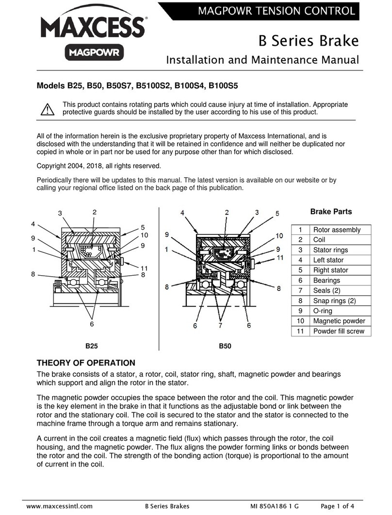
THEORY OF OPERATION
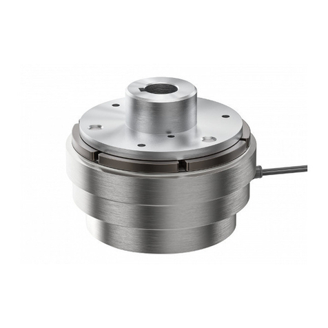
The brake construction consists of two stators, a rotor, a coil assembly, magnetic powder, and two bearings. The
bearings support and align the rotor with the stators, and allow the rotor to rotate within the brake assembly. The
magnetic powder occupies the space between the stators and the rotor, and represents a key element in the
operation of the brake.
The stators are connected to the machine frame through a torque arm and remain stationary. The rotor is
connected to a rotating machine shaft, which supports the weight of the brake. The magnetic powder functions as
the adjustable bond or link between the stators and the rotor. It is the medium for the transmission of torque.
An electric current in the coil creates a magnetic field (flux), which passes through the stators, magnetic powder,
and the rotor. The flux aligns the powder particles, forming a bond or link between the stators and the rotor. The
strength of the bonding action (torque) is proportional to the amount of current in the coil. The torque is transmitted
to the rotating shaft through the rotor. See figure 1 for a cross-sectional view of the brake.
MECHANICAL INSTALLATION
WARNING –The brake device contains rotating parts which could cause injury due to crushing.
Appropriate protective guards must be installed by the user according to his use of this product.
WARNING –Death or injury can result from electric shocks.
Installation of the brake device must be performed when there is no electrical power in the system.
WARNING –Danger of injury from crushing.
Installation of the brake device must be performed only when the machine has been stopped and has
been secured from being turned on again.
WARNING –Danger of falling down or muscle or skeletal injury during maintenance and repair.
The brake devices, especially the larger designs, are heavy. Appropriate equipment is to be used and
the safety rules of the company must be observed.
1. Unpack the brake, check for completeness and transport damages and verify the nameplate. The GBE/M and
GBF/M models should be packed with 2 eye bolts to facilitate lifting and positioning of the brake.
2. The rotor shaft centerline must be mounted within 30° of the horizontal plane.
3. Prior to installation, manually check the rotation of the rotor to observe that it is smooth and free of binding or
scraping.
4. Mount the brake on the shaft and tighten the two set screws in the collar using the torque from table 1. This will
prevent axial movement of the brake. The GBE/M and GBF/M models have eye bolts which may be installed in
the threaded holes to facilitate lifting and positioning of the brake. After installation of the brake on the shaft,
remove the eye bolts and store in a safe place for use when removing the brake from the shaft for repair.
WARNING –Danger due to falling or flying objects.
Do not leave the lifting eye bolts installed during operation of the brake. These could come loose and
fall or be projected from the brake during operation.
Table 1. Collar Set Screw Tightening Torque
