HOPPER SWITCH
The vacuum is equipped with a safety
switch to prevent the machine from being
switched on when the hopper cover is
open.
0
PERATI
N
G
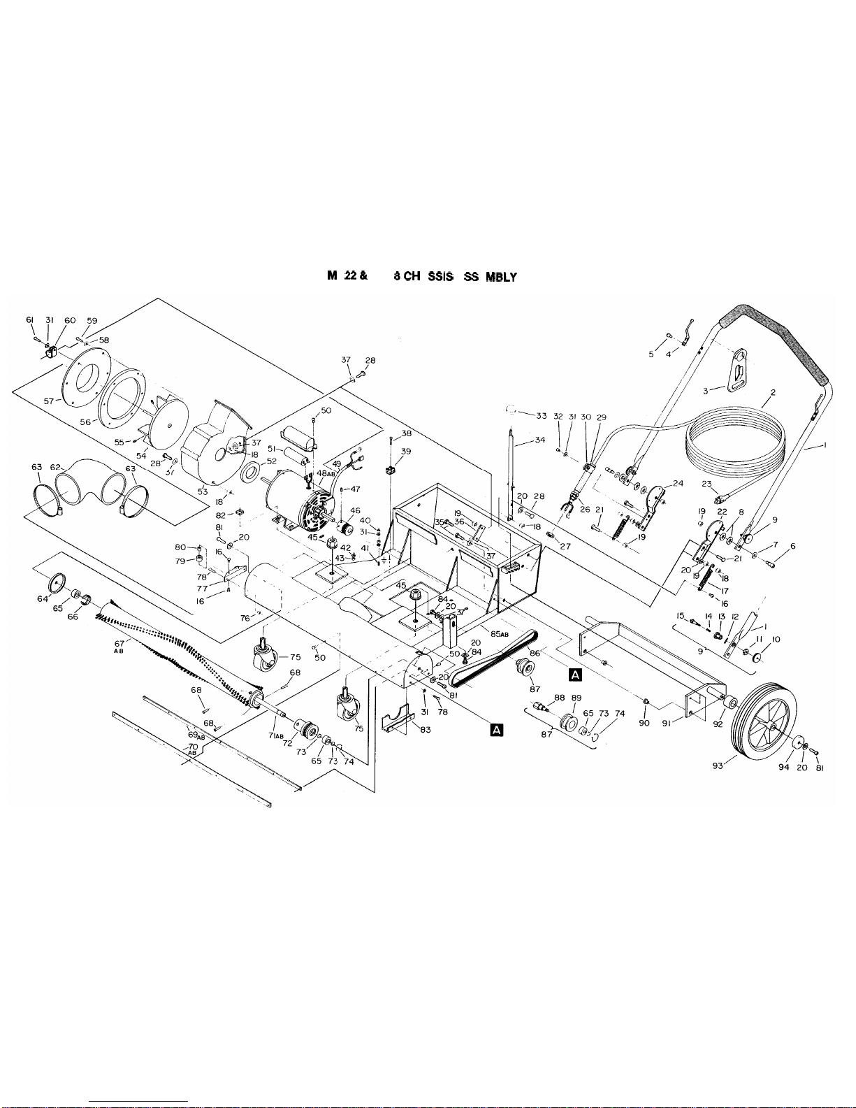
MAXI
MATlC VACUUM
The vacuum is designed for use on large
carpeted areas such as airport concourses,
hotel ballrooms/meeting rooms, etc.
1.
Large debris such as paper cups,
plates, etc., should be picked up before
starting the cleaning process.
2.
Planyour cleaning route towork away
from the electrical source. Move ma
-
chine forward at a steady pace.
WARNING:
Do not push vacuum
over power cord while machine is run
-
ning. Always lift cord over vacuum.
WARNING:
Before opening hopper
cover switch off machine and watt
until fan rotation stops to prevent
dust and debris from being ejected.
3.
To
keep the vacuum operating at max
-
imum efficiency: Periodically switch off
the machine, shake vacuum bag to
allow the finer dirt and dust
to
settle
into the hopper. Open hopper cover,
lift out dust bin and empty.
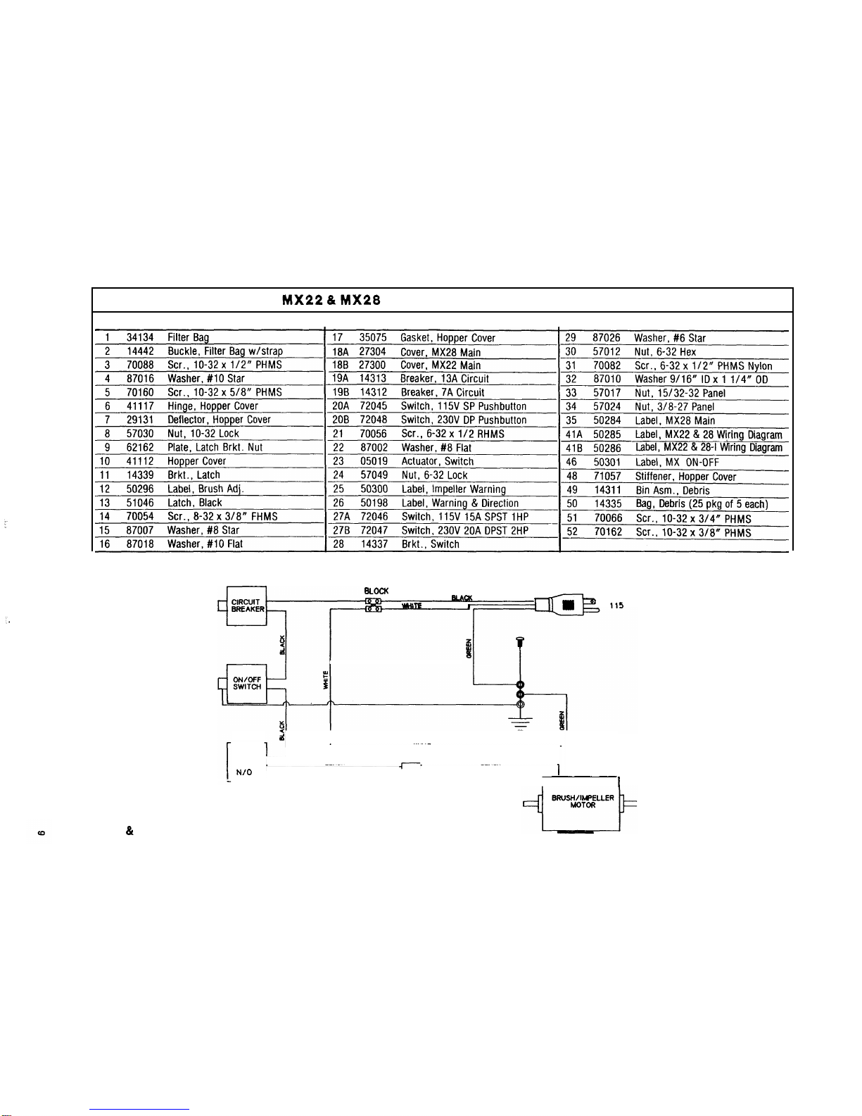
CIRCUIT BREAKER
The vacuum is equipped with a circuit
breaker to protect the motor in the event
an excessive overload condition occurs.
If the breaker trips, wait 2 minutes before
resettlng. If the breaker trips immediately
after resetting, check for probable cause
such as:
A.
Brushadjustment set too low.
B.
Obstructions in brush roller or impeller.
REGULAR MAINTENANCE
1.
Shake down bag and empty debris bin,
daily.
2.
Check power cord for damaged or fray
-
ed insulation.
3.
Return brush adjustment lever to
“store” position when machine is not
Inuse.
4.
Every
4
to 6 months remove wheels,
clean axles, and apply a thin coating
of silicone lubricant to axles.
5.
The filter bagcan be washed twice be
-
fore losing the filtering ability. This
should be done using a mild deter ent
incool water and hung up to dripjry.
SERVICING THE MAXIMATIC
WARNING:
Remove machine power
cord from electrical source before making
any repairs of adjustments to the machine.
I
M
P
E
LL
ER ASSEMB
LY
/
B
R
USH
DRIVE MOTOR IMPELLER
1.
Removeintake duct.
2.
Removeimpeller housing cover.
,3.
Loosen (2) screws in impeller and
remove from motor shaft.
MOTOR
1.
Loosen idler and roll belt off motor
pulley.
2.
Remove intake duct, impeller and
housing.
3.
Disconnect motor leads from terminal
block.
4.
Remove
(4)
bolts holding motor to
chassis.
NOTE:
When re
-
installing motor use a
straight edge to check pulley alignment
betweenbrush and motor pulleys.
To access impeller assembly/belt and
motor.
1.
Release hopper cover latches and tilt
cover back.
2.
Remove
(4)
screws holdin main cover
to chassis. (2) located at Bront corners
and
(2)
at front inside of rear wheels.
Lift up
RIGHT
side of cover and slide
to left to remove.
BELT/B
R
U
S
H
1.
Loosen idler pulley and roll belt off
motor pulley.
2.
Removebelt/brush pulley guard.
3.
Removescrew from each end of brush
shaft and remove brushassembly.
NOTE:
When installing a new belt or
motor, centerline distance between
motor shaft and brush shaft should be
set at
12
318 Inches.
10
I1
A.
Terminal
Block
0.
Cover
B.
Intake
Duct
C.
Impeller
Housing
F.
Belt
E.
ImpellerlBrush Motor
CASTERS/BRUSH HOUSING
SHOES
NOTE
When replacing casters
or
shoes
the dimensions shown in Drawing 12 must
be made to maintain efficiency of the
vacuum.
NOTE:
Make adjustments with the ma
-
chine instore position setting on a
LEVEL
surface andwith the casters pointing rear
-
ward.
1.
The distance between surface and
bottom of rear brush housing should
be 9/16 in. Check both right and left
side of housing.
2.
When replacing shoes install a screw
at each end of shoe first. Using a
straight edge install balance of screws
keeping shoe straight.
,
..
.
-.
.
-
-
STRAIGHT
EDGE
MACHINEMUST
BE
IN
STORE
POSITION
\
I
’
’j4”
’
MAKE ADJUSTMENTS
REAR SHOE WITH CASTERS
POINTING REARWARD
FRON~
SHOE
BRUS~HOUSING
5