maximatecc CCpilot VI User manual

1.1
Technical manual
Date: Jul 6, 17
www.maximatecc.com
Technical manual
CCpilot VI

CCpilot VI - Technical Manual
Date: Jul 6, 17
www.crosscontrol.com
Contents
Contents .............................................................................................................................................2
Introduction ................................................................................................................................3
1.1 Product models.......................................................................................................................... 3
1.2 Conventions and definitions ................................................................................................... 4
1.3 Identification .............................................................................................................................. 4
1.4 Care ............................................................................................................................................. 4
1.5 Environment and Environmental Tolerance......................................................................... 5
1.6 Cleaning...................................................................................................................................... 5
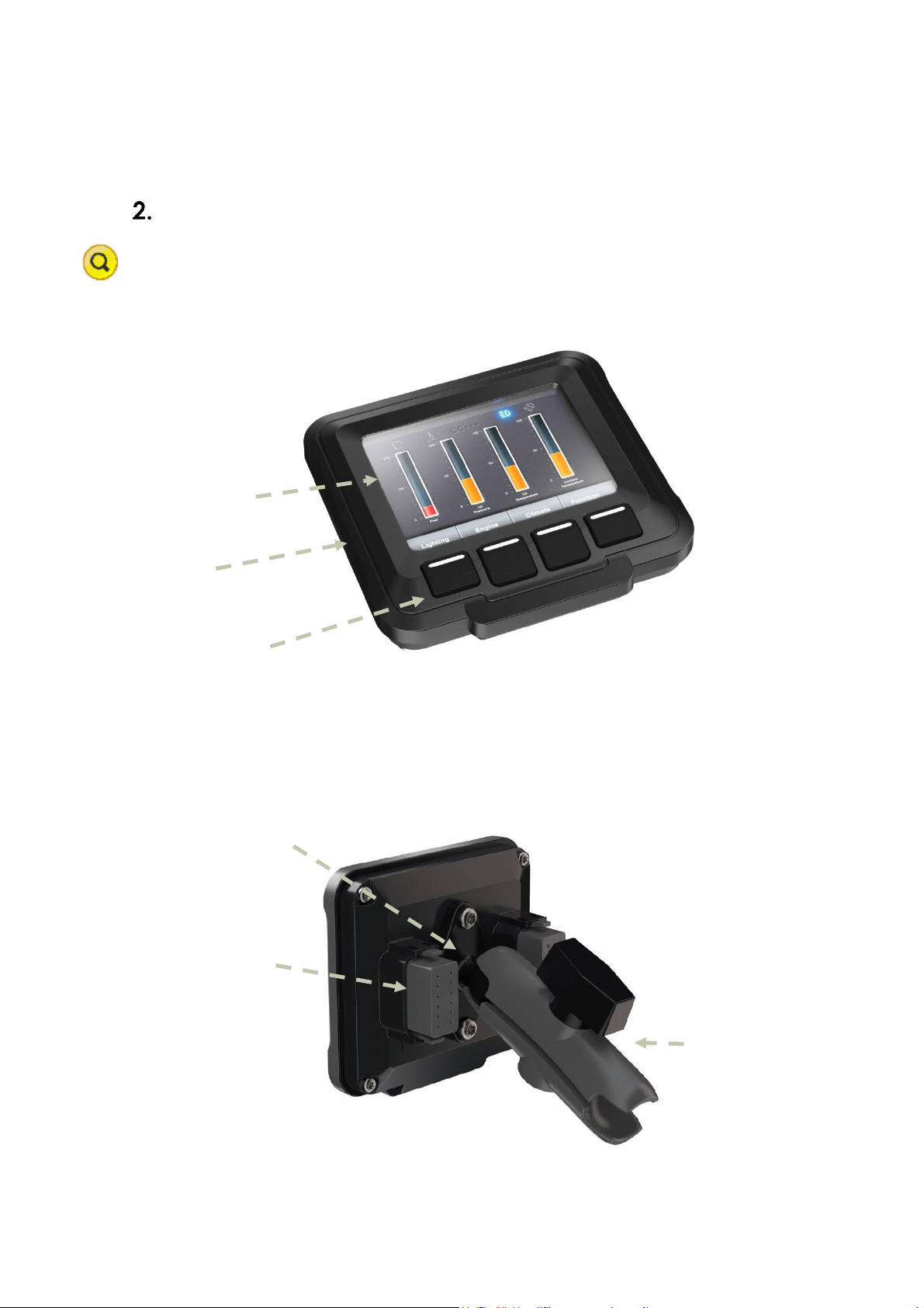
Overview ....................................................................................................................................6
1.7 Front side ..................................................................................................................................... 6
1.8 Rear side...................................................................................................................................... 6
Installation ..................................................................................................................................7
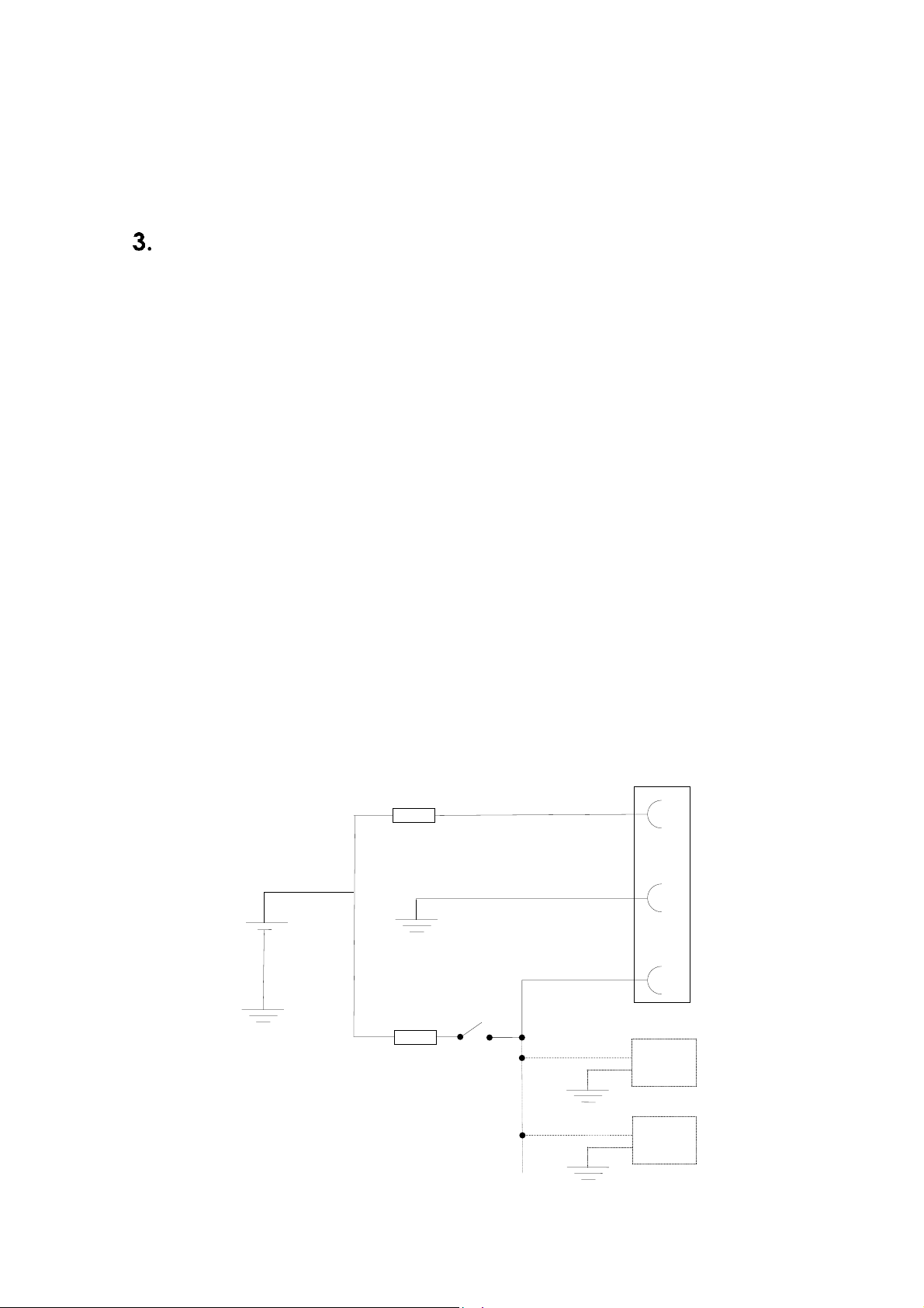
1.9 Connecting to power supply .................................................................................................. 7
1.10Mounting ..................................................................................................................................... 8
1.11Environmental considerations................................................................................................. 8
1.12Cables ......................................................................................................................................... 9
Basic operations ......................................................................................................................10
1.13Starting Up................................................................................................................................. 10
1.14Turning off.................................................................................................................................. 10
1.15Adjusting the screen brightness............................................................................................ 10
1.16Clock back-up battery........................................................................................................... 10
Interface overview ..................................................................................................................11
1.17Storage memory...................................................................................................................... 11
1.18Buzzer ......................................................................................................................................... 11
1.19CAN............................................................................................................................................ 11
1.20USB .............................................................................................................................................. 11
1.21Configurable inputs ................................................................................................................ 11
1.22Switched Outputs .................................................................................................................... 11
Connectors ..............................................................................................................................12
Connector layout .................................................................................................................... 12
Specifications...........................................................................................................................13
Standard models connectivity level.................................................................................... 13
1.23Technical data......................................................................................................................... 13
1.24Environmental tolerance ....................................................................................................... 14
1.25Weight and dimensions.......................................................................................................... 16
Technical Support....................................................................................................................17
Trade Mark, etc. ......................................................................................................................18
Index .........................................................................................................................................19

www.maximatecc.com
Introduction
CCpilot VI is an easily configurable, full-colour 3’’5 display enabling appealing user interfaces in a
compact form factor. Designed especially for the off-highway and industrial markets, CCpilot VI
offers exceptional readability and all-weather performance. It is suitable for both bracket mounting
and integration in a dashboard.
This technical manual and reference handbook provides important information regarding the
hardware and basic usage. For software and operating system specifics please see additional
documentation.
1.1 Product models
This documentation is applicable for CCpilot VI. This platform also enables customization of
hardware and software. Described herein are the possibilities which can be obtained using above
product models, additional features are described in model specific documentation.

www.maximatecc.com
1.2 Conventions and definitions
The following definition is used to separate unit specific details. The observe symbol is also used to
highlight such difference.
Defines
Use
CCpilot VI
Information that is specific for CCpilot VI
VI or VI device
Information that applies to CCpilot VI
The observe symbol is used to highligt information in this document.
The exclamation symbol is used to highlight important information.
Text formats used in this document.
Format
Use
Italics
Paths, filenames, definitions.
Bold
Command names and important information
1.3 Identification
On the backside of the VI device there is a label containing version and serial numbers which
identify your unique device. Take note of them. During service and other contact with the supplier
it is important to be able to provide these numbers.
1.4 Care
During welding or other service on the machine, all cables to the VI device shall be
disconnected.
Serviced shall only be made by authorised personnel. If the unit is opened by unauthorised
personnel, the guarantee will cease to be valid.
Scratches, or in the worst case damages, to the display occur easily if it comes in contact
with a sharp edge or hard material. In order to increase the longevity of the screen, this is
naturally something which should be avoided.
The Flash memory used for storage is durable; however as with all flash memory types the
write cycles are limited. Avoid unnecessary writing to the flash memory.
If the unit becomes too hot it will operate at a limited speed and can also be damaged.
Therefore, do not cover the unit by covering it, for example hanging a jacket or other
clothes on it.
Consider traffic safety when CCpilot VI is installed and whenever it is used. maximatecc
does not recommend that CCpilot VI or its accessories be used actively by the driver when
a risk of injury to people, or damage to property, is present.
Be advised that the VI device draws power from the vehicle battery. This can result in the
inability of the vehicle to start if the on-board computer has been on for a period of time
without the vehicle engine running.

www.maximatecc.com
1.5 Environment and Environmental Tolerance
The VI device has been designed to cope with tough environmental demands. Strict tests have been
conducted on the unit in order to ensure that it fulfils the expectations of a rugged unit. Much work
has been performed to choose and design internal components so that they, under all
circumstances and in the best possible way, provide you with a dependable and user-friendly
working instrument. Within the chapter Specifications, a list of standards can be found according
to which VI device has been tested and approved.
The VI device is preferably placed in a way that prevents exposure to water contact. It is also
important that it is mounted securely on a stand or the like to inhibit the unit from moving and
thereby becoming damaged, damaging the vehicle and/or people during, for example, a traffic
accident.
1.6 Cleaning
To ensure proper and reliable functionality over time, the unit shall be wiped cleaned of dirt and
dust. Use a suitable light damp rag to clean the unit.
Never use alkaline, alcoholic or other chemicals for cleaning which can damage the unit.

www.maximatecc.com
Keypad for
Navigation
3.5” Color QVGA
Rugged
Engineering Resin
Enclosure
Overview
The VI device is a compact, robust and versatile indication Display. It is equipped with, a large
number of connection alternatives such as CAN, configurable I/O, and USB.
1.7 Front side
1.8 Rear side
On the rear side of the VI device there are the external connectors (Duetsch DTM-12), which are
described in more detail in the chapter Connectors. There are also mounting holes for fasteners for
attaching the RAM mount shown or bracket for panel mounting.
GORE-TEX
membrane,
under mount
for added
protection
External
connectors
RAM mount
(purchased
separately)

www.maximatecc.com
Installation
Install the device in such a way that is considered safe and does not expose any unnecessary stress
to the unit. In this section, some recommendations are made regarding installation.
1.9 Connecting to power supply
This instruction address vehicle installations but the principle is the same also for other types of
installations. See also the description of the pin outs for the Power Supply Connector under the
section External interface description.
Carefully follow the connection instructions below. Make sure that all contacts are angled
correctly and that they do not have to be forced, but lock gently and pliant.
GND Pin J1-2 is connected to the vehicles ground.
Battery Pin J1-1, i.e. the display’s power supply (+12/+24 VDC), should be connected
directly to the vehicle’s battery through 10 A fuse (F1). Wire gauges shall be dimensioned
with respect to cable length, supply voltage etc. Minimum cable area is TBD.
The Switched Power Input Pin J1-3, i.e. the display’s on/off signal is connected via the
vehicles ignition switch (S1). The maximum allowed input current for the ignition switch
signal is 2 mA. The fuse F2 fuse rating and wire gauge shall be dimensioned for the total
switch current.
GND
1
2
F1
10 A
GND
BATTERY
S1
Connector (J1)
3
Min: AWG 16
Min: AWG 16
F2
XXm A
Unit A
GND
Unit B
GND
Imax 2 mA

www.maximatecc.com
By connecting the power supply according to the illustration above, the device will automatically
start when the main switch or turnkey is turned on, and shut down when the switch or turnkey is
turned off.
i. Precautions
If applicable connect the power supply to the device before any main switch, as per the illustration
above. If this is not possible, ensure that the device is turned off using for example the on/off
button or turnkey functionality before turning off the main switch or in any other way making the
computer powerless.
Sudden power disruptions may cause the device to shut down, potentially causing lost or corrupt
data. If for example the power fluctuates when starting the vehicle engine, the device should be
started after the vehicle engine is running.
Ensure that any application data is saved before turning off the device.
During welding or other service on the machine, all cables to the VI device shall be disconnected.
1.10 Mounting
CCpilot VI is preferably mounted using a RAM-B-238U Mount which allows adjustment of the
display’s position and angle.
To fasten, use the appropriate M5 x 0.8 button head screw of type MRT (Torx). The length of the
screws should be 30mm when using the Spacer maximatecc P/N 123295. If the spacer is not used
the screw length should be 12mm. The recommended torque for the screws is 1.5-2.0 Nm. Using a
split ring or toothed lock washer is recommended.
An alternate mounting method would be in a panel using the 123233 Mounting kit.
Ensure that CCPilot VI is mounted to a smooth, flat surface. Fastening the unit to an uneven
surface may stress the enclosure, damage the outer flange or possibly even flex the circuit board
inside, leading to a premature failure.
Ensure the M5 mounting screws are clean and dry, and apply torque of 1.5-2.0 Nm. Use lock
washers.
1.11 Environmental considerations
The device shall be placed in a way that prevents the unit from direct exposure to water.
Use caps on any connectors that do not have attached cables.
On the back side of the unit there is a hydrophobic membrane, seen as a white disc. This
membrane must never be faced upwards when the unit is mounted. Be cautious not to
insert any object into this hole since it can puncture the hydrophobic membrane, leaving
the unit unprotected from moisture and dust intrusion. If the membrane is punctured the
guarantee is void.
To enable sufficient cooling, the VI device must be installed so that air is able to circulate
around the device, avoid installing the device near hot air vents or the like. There must be
at least 50 mm free distance around the unit.

www.maximatecc.com
Loose mounting bolts are the most common reason for excessive vibration. Mounting bolts
may become loose due to improper techniques such as missing lock washers, over
tightening or under tightening. Proper tightening requires clean dry bolts, and a torque
wrench.
When CCpilot VI or any device is installed in a vehicle environment it is important that the
installation is traffic-safe. maximatecc does not recommend that CCpilot VI or its
accessories are used actively by the driver or operator when a risk of injury to people, or
damage to property, is present.
1.12 Cables
Cables shall be installed in such a way that they don’t run any risk of being damaged, pinched or
worn.
Avoid bending and twisting cables
Strain-relief on cables near the connection to the respective unit
Properly snap the connectors to give good contact and avoid unnecessary strain

www.maximatecc.com
Basic operations
This section covers basic operation of the VI device such as start-up and shut-down.
1.13 Starting Up
Start CCpilot VI via the vehicle’s ignition switch. A menu will appear on the CCpilot VI’s LCD
screen as an indication that the unit is starting up.
1.14 Turning off
Turn off CCpilot VI via the vehicle’s ignition switch.
i. Shutting Down
To ensure that data does not get lost or the flash memory becomes corrupt, it is recommended that
all necessary data shall be saved and all programs closed before the unit is shut down.
ii. Standby
In this state the ignition switch is in the OFF position but the unit is supplied power through the J1-
1 power input. The display can be woken up from this state by any of the following events:
Keypad button press
Configurable Input Change Of State
CAN Receive Event
Real Time Clock (Alarm Clock)
NOT SURE IF THESE FEATURES ARE ACTUALLY IMPLEMENTED!!!!!! SW input.
1.15 Adjusting the screen brightness
LED screen brightness is software configurable. Adjustability range is 0-100% in 1% increments.
1.16 Clock back-up battery
Time and date information is stored in a memory sustained by a rechargeable back-up battery. In
its fully charged state, the battery has a lifetime of approximately 30 days.

www.maximatecc.com
Interface overview
This section describes the interfaces on the VI device. Note that depending on product model, all
interfaces may not be present. See the section standard product model equipment level for
information on the respective unit configuration.
1.17 Storage memory
16 Mbytes of NAND Flash memory is used for data storage. A 64 Mbyte version of the CCpilot VI is
also available.
1.18 Buzzer
A buzzer that can be used for user notifications exists on the VI. Activation and use of the buzzer is
software configurable.
1.19 CAN
The VI device has two CAN interfaces that meet the CAN ISO 11898 2.0B specification. The CAN
shields are terminated (AC coupled to ground) per the SAE J1939 physical layer specification.
1.20 USB
USB ports enable connection of a multitude of devices to the VI device. The USB port is designed
to the USB 2.0 standard.
The USB port can supply up to 500 mA.
1.21 Configurable inputs
There are four configurable inputs available on the VI device. The input configuration setting is
controlled via software. The input configurations consist of:
Voltage
Resistive
Frequency
Switched To Ground (Internal Pull Up)
Switched To Battery (Internal Pull Down)
1.22 Switched Outputs
Two switched outputs to control external loads such as a buzzer, relay or lamp are provided. The
outputs have a maximum current rating of 4 Amps per channel.
PWM duty cycle and frequency is adjustable via software.
The outputs are protected from short circuit conditions in addition to incorporating fault detection
to determine if the output has been shorted to ground, battery or is open circuit.

www.maximatecc.com
Connectors
All connectors are accessible from the rear of the unit. The connectors are marked with a 1(J1) and
a 2(J2).
Use caution and avoid plugging/unplugging of connectors when the display is on.
Always replace a damaged cable. If the pins become bent or damaged they may not function
correctly, or in the worst case, the on-board computer or other equipment may be damaged.
Connector layout
Notice that the connector descriptions are those which are located on the unit, not those that the
attached cables shall have in order to mate with them.
J1 Connector
Pin #
Default signal
Comments
12-pin Deutsch
DTM Series Key A
1
+12/24 VDC
Main Power Input
2
GND
Main Ground Input
3
Switched Power +12/24 VDC
Iginition Input
4
Switched Output 1
5
Switched Output 2
6
7
8
9
10
11
12
CAN 1 Shield
CAN 1+
CAN 1-
USB Ground
USB Data –
USB Data+
USB VBus
USB Power Out
J2 Connector
Pin #
Default signal
Comments
12-pin Deutsch
DTM Series Key B
1
Configurable Input 1
2
Configurable Input 2
3
Configurable Input 3
4
Configurable Input 4
5
Analog Ground
6
7
8
9
10
11
12
CAN 2 Shield
CAN 2+
CAN 2-
Not Used
Not Used
Not Used
Not Used

www.maximatecc.com
Specifications
The specification may vary depending on your computer configuration.
Standard models connectivity level
Interface / Feature
CCpilot VI
CAN bus
2
USB Host
1
Configurable Inputs
4
Switched Outputs
2
1.23 Technical data
Kernel
Processor
Freescale Kinetis K70, ARM Cortex M4, 150 MHz
Program Memory
1 MB
Data storage
16 MB, NAND flash
RAM memory
8 MB, DDR
Interfaces
CAN
Type
Driver
Baud Rate
CAN ISO 11898-2, 2.0B, (High Speed CAN)
SN65HVD234
250 kbit/s
USB
Type
Speed
Host port
Host, V 2.0
Full speed, max 12 Mbit/s
5 V, max 500 mA
Configurable Inputs
Mode
Input Range
Voltage
0 to 5 VDC
Accuracy
6mV
Resolution
.4mV
Mode
Resistance
Range
1 - 1000Ω
Accuracy
3Ω ±2%
Resolution
2Ω
Mode
Frequency
Range
1 –12 kHz
Accuracy
3 Hz
Switched Outputs
Maximum Current
Input Voltage Range
4A per channel, 8A total
9 to 32V

www.maximatecc.com
Software
Operating system
MQX
Additional software
TBD
Display
3.5”
Type
Resolution
Colour depth
Backlight
TFT
QVGA, 320 x 240
24 bit
LED, 400 cd/m2
Power Supply
Supply Voltage
12 or 24 V nominal
Power Consumption
< 1 A at 24 V
1.24 Environmental tolerance
Environmental Test
Standard
Dry Heat
TBD
Operating: +70°C, 24h
Storage: +80°C, 24h
Damp Heat
TBD
Operation: +25°C / +55°C
>93% RH 6*24h
Cold
TBD
Operating: -40°C, 24h
Storage: -40°C, 24h
Vibration
TBD
0,01 g2/Hz 10-200 Hz 3x0.5h
Shock
TBD
5 g / 11ms 3x ±1000 bumps
EMC Electrical Transient
ISO 7637-2
Pulse 1: -50V
2: +25V
3a: -35V
3b: +35V
4: -5V
5: +70V
EMC Immunity, ESD
ISO 10605
15 kV air, 8 kV contact
EMC Immunity, RF
ISO 11452-2
ISO 11452-4
RF electromagnetic field
200-1000MHz 30V/m
Bulk Current Injection
20-200MHz 60mA
EMC Emission
ISO 14982
Radiated Nar.b. Bro.b.
MHz dBµV/m dBµV/m
30-75 54-44 64-54
75-400 44-55 54-65
400-1000 55 65
EMC Radiated RF immunity
EN 61000-4-3
RF electromagnetic field
80M-1GHz 10V/m
1G-2GHz 3V/m
2G-2,7GHz 1V/m
EMC Induced RF 1)
EN 61000-4-6
0.15-80MHz 10V
EMC Radiated RF emission
CISPR 25
MHz dBµV/m
.150-54MHz 40
230-1000MHz 47
Enclosure
EN 60529
IP65

www.maximatecc.com
The tests are performed with 24 V power level. The environmental tolerance may be affected by
external factors like mounting and shielded cables etc.
i. FCC Notice to Users
Users are not permitted to make changes or modify the device in any way. Changes or
modifications not expressly approved by the party responsible for compliance could void the user’s
authority to operate the equipment.

www.maximatecc.com
1.25 Weight and dimensions
i. CCpilot VI 3.5”
Description
Enclosure size
107.7 x 103.1 x 42.7 mm (W x H x
D)
Weight
198 g

www.maximatecc.com
Technical Support
Contact your reseller or supplier for help with possible problems with your VI device. In order to
get the best help, you should have your VI device in front of you and be prepared with the following
information before you contact support.
Part number and serial number of the unit, which you find on the brand label
Date of purchase, which is found on the invoice
The conditions and circumstances under which the problem arises
LED indicator flash patterns.
Possible error messages which are shown.
Operating system type and its version number.
The VI Device log files (if possible)
Prepare a system report on the VI device, from within CCsettings (if possible).
Information regarding possible external equipment which is connected to the VI device.

www.maximatecc.com
Trade Mark, etc.
© 2011 CrossControl AB
All trademarks sighted in this document are the property of their respective owners.
CCpilot is a trademark which is the property of CrossControl AB.
Intel is a registered trademark which is the property of Intel Corporation in the USA and/or other
countries. Linux is a registered trademark of Linus Torvalds. Microsoft and Windows are registered
trademarks which belong to Microsoft Corporation in the USA and/or other countries.
CrossControl AB is not responsible for editing errors, technical errors or for material which has
been omitted in this document. CrossControl is not responsible for unintentional damage or for
damage which occurs as a result of supplying, handling or using of this material including the
devices and software referred to herein. The information in this handbook is supplied without any
guarantees and can change without prior notification.
CrossControl respects the intellectual property of others, and we ask our users to do the same.
Where software based on CrossControl software or products is distributed, the software may only
be distributed in accordance with the terms and conditions provided by the reproduced licensors.
For end-user license agreements (EULAs), copyright notices, conditions, and disclaimers,
regarding certain third-party components used in the VI device, refer to the copyright notices
documentation.

www.maximatecc.com
Index
B
Back side................................................................6
Basic operations .................................................10
Battery ............................................................. 7, 10
Buzzer....................................................................11
C
Cable installation..................................................9
CAN ......................................................................11
Care........................................................................4
Cleaning ................................................................5
Compact Flash ...................................................11
Connectors..........................................................12
Contact support .................................................17
D
Digital inputs ........................................................11
Dimensions...........................................................16
Display ....................................................................6
E
Enclosure size.......................................................16
Environmental test..............................................14
Environmental tolerance ..................................14
Environmental Tolerance ....................................5
Ethernet Connector ...........................................12
External interface description ..........................12
F
Front ........................................................................6
Fuse .........................................................................7
G
GPS........................................................................11
H
Hook up of Power supply ....................................7
I
Inputs ....................................................................12
Installation..............................................................7
Installing cables ....................................................9
Introduction ...........................................................3
M
Maintenance ........................................................5
Memory ................................................................11
O
ON/OFF...................................................................7
Outputs.................................................................12
Overview................................................................6
P
Pins ........................................................................12
Ports.......................................................................12
Power supply connector...................................12
Power supply installation.....................................7
Push-buttons ........................................................10
R
Rain/Moisture ........................................................9
Rear.........................................................................6
S
Shutting down .....................................................10
Specification .......................................................13
Standard models ................................................13
Starting Up ...........................................................10
Storage.................................................................11
Support .................................................................17
Suspend................................................................10
T
Technical data....................................................13
Technical Support ..............................................17
Test standards .......................................................5
Trade Mark...........................................................18
Turning off ............................................................10
Turning on ............................................................10
U
USB.........................................................................11
V,W
Vehicle´s fuse ........................................................7
Weight ..................................................................16

Table of contents
Other maximatecc Desktop manuals
Popular Desktop manuals by other brands

Premio Computer
Premio Computer Apollo user manual

Enwork
Enwork Ambition Series Installation guides

Lenovo
Lenovo ThinkCentre M77 Guide d'utilisation

Premio Computer
Premio Computer Apollo/Shadowhawk user manual

Moxa Technologies
Moxa Technologies V2403 Series Hardware user manual

HP
HP Compaq dx2000 MT reference guide