maximuscle 335 / 8687 User manual

0
Assembly & User Instruction – Please keep for future reference 335 / 8687
Two Station Home Gym
Important – Please read these instructions fully before assembly or using
These Instructions contain important information which will help you get best from your
equipment and ensure safe and correct assembly, use and maintenance.
If you need help or have damaged or missing parts, call the Customer Helpline: 0845 600 0464

1
Contents
Safety Information 2
Components - Parts 3—5
Components – Fixing 6
Assembly Instruction 7—29
Exercising Information 30—38
* Before Starting to exercise 30—31
* Muscle Chart 32
*Basicaerobic training programme 33-35
* Weight resistance chart 36
* Warming up and Cooling down 37—38
* Weight bench exercise guide 39—47
Care and Maintenance 48
Exploded Parts List 49—50
Guarantee 51

2
To reduce the risk of serious injury, read the entire manual before you assemble or operate the Maximuscle Two
Station Home Gym, In particular, note the following safety precautions:
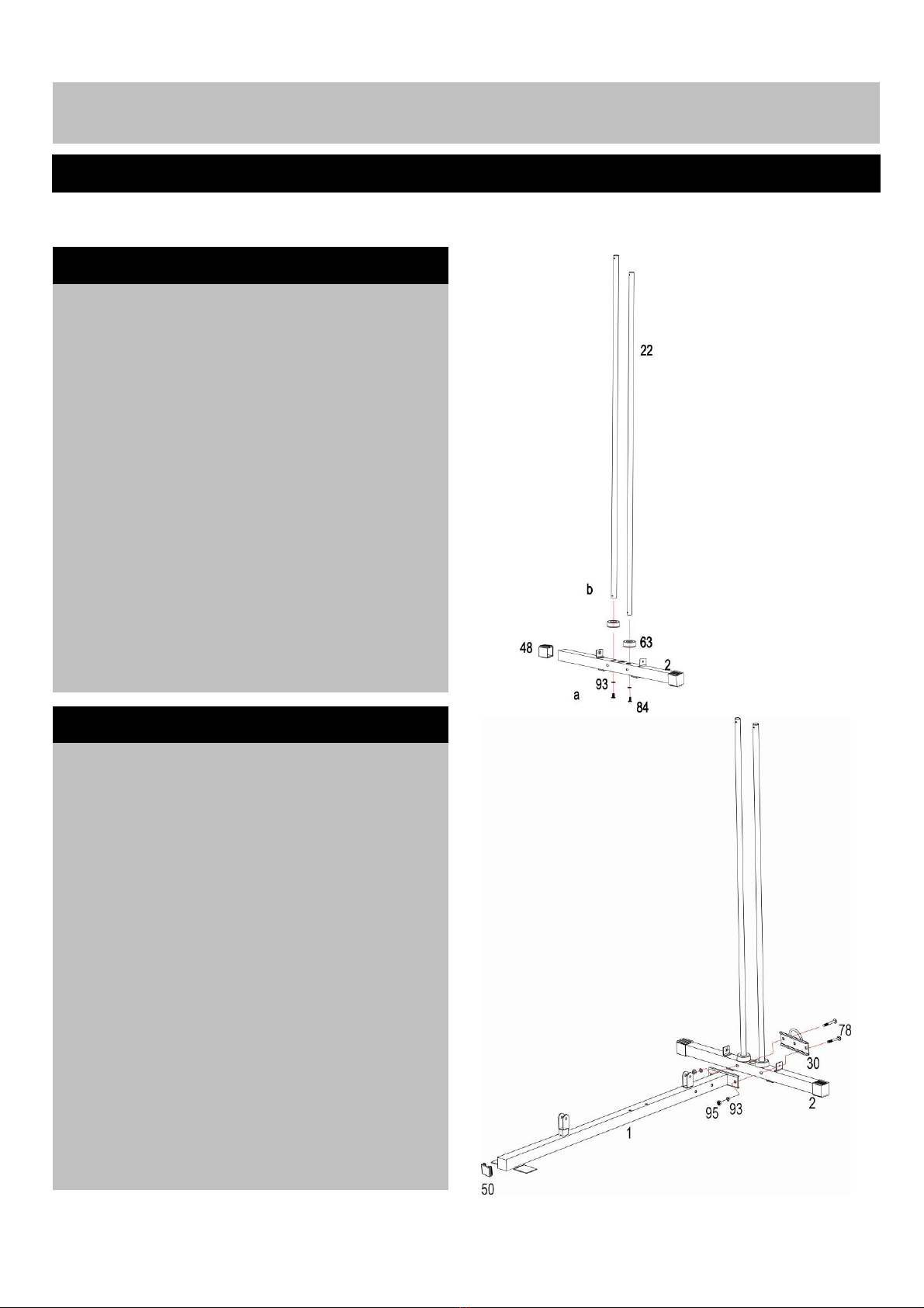
Assembly
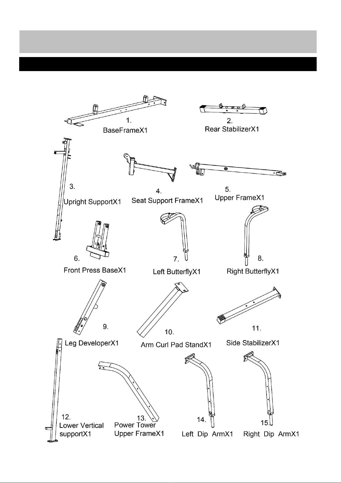
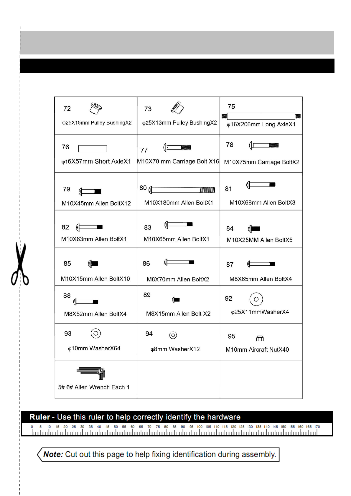
• Check you have all the components and tools
listed on pages 3 and 6, bearing in mind that, for
ease of assembly, some components are
pre-assembled.
• Remove all fittings from the plastic bags and
separate them into their group.
• Keep children and animals away from the work
area, small parts could choke if swallowed.
• Make sure you have enough space to layout the
parts before starting.
• The assembly of this equipment is best carried
out by 2 or more people.
• Assemble the item as close to its final position
(in the same room) as possible.
• Position the equipment on a clear, level surface.
Do not use the equipment near water or outdoors.
• Dispose of all packaging carefully and responsibly.
Using
•Keep children and pets away from the
equipment at all times. Do not leave children
unattended in the small room with the
equipment.
• It is the responsibility of the owner to ensure that
all users of this product are properly informed as to
how to use this product safely.
• This product is intended for domestic use only.
Do not use in any commercial, rental, or institutional
setting.
• Before using the equipment to exercise, always do
stretching exercises to properly warm up.
• Use the Equipment only for its intended use as
described in this manual. Do not use attachments
not recommended by manufacturer.
• If the user experiences dizziness, nausea, chest
pain, or other abnormal symptoms stop the workout
and seek immediate medical attention.
• Only two person at a time should use the
equipment.
• Always wear appropriate workout clothing when
exercising. Do not wear loose or baggy clothing,
since it may get caught in the equipment. Wear
athletic shoes to protect your feet while exercising.
• Disabled persons should not use the equipment
without a qualified person or doctor in attendance.
• Never operate the equipment if the equipment is
not functioning properly.
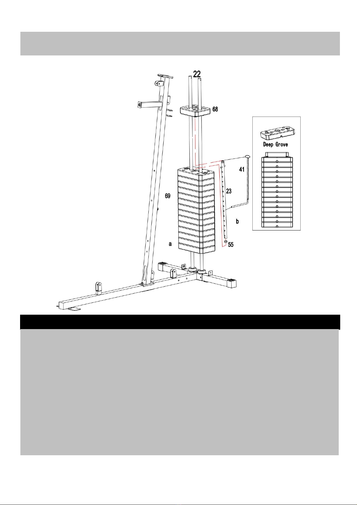
• Lock the Weight stack select rod at the last hole
into the lock ring on the Rear stabilizer with the
Weights select pin when you finish workout.
• Examine the equipment frequently especially for
the easy damaged parts. The safety level of the
equipment can only remain if the examined
regularly. Replace any defective components
immediately. Do not use the equipment until it has
been repaired.
Parents and others in charger of children should be
aware of their responsibility because the natural
play instinct and the fondness of the experimenting
of the children can lead to situations and behaviour
• A spotter is recommended during exercise.
• Maximum User’s Weight: 125Kgs.
• This product conforms to: (BS EN957)
- PARTS 1. 2 class (H) - Home Use - Class (C).
- It’s NOT suitable for therapeutic purposes.
• This exercise product has been designed and
manufactured to comply with the latest (BS EN 957)
British and European Safety Standards.
Warning: Before beginning any exercise program, consult your Doctor. This is especially
important for persons over the age of 35 or persons with pre-existing health problems. You
MUST read all instructions before using any fitness equipment. Argos and its associates assumes no
responsibility for personal injury or property damage sustained by or through the use of this product.
Important – Please read fully before using and assembly
Safet
y
Information

3
:
Note: Some of the smaller components may be pre-fitted to larger components. Please check carefully
before contacting Argos regarding any missing components.
Please check you have all parts list below
Components-parts If you have any damaged or missing parts, Please
Call the Customer Helpline: 0845 6000 464

4
Components--parts

5
Components--parts

6
:
NOTE:Some of the fixings are pre-fitted to the larger components. Please check carefully before
contacting Argos regarding any missing fixings
Please check you have all fixings listed below
Com
p
onents – Fixin
g
s

7
:
NOTE: Tool required assembly the machine: two adjustable wrenches, and one Philips screw driver
Recommend the assembly if this equipment is carried by two person
Assembly Instruction
a. Insert two Weight stack guide rods(22)
into the holes on the Rear stabilizer (2), fix
using two M10 x 25mm Allen bolts (84), two
Ø10mm Washers (93) from the bottom.
b. Slide two Rubber cushions (63) down to
the Weight stack guide rods (22).
Step 1
Step 2
a. Attach Base frame (1) to the Rear stabilizer
(2), line up the holes, fix using two M10 x
75mm Carriage bolts (78), one U–shaped
bracket (30), two Ø10mm Washers (93) and
M10 Aircraft nuts (95).

8
Assembl
y
Instruction
Step 3
a. Attach the Upright support (3) onto the Base frame (1), Align the holes, fix using two M10 x
70mm Allen bolts (77), one Bracket (29), two Ø10mm Washers (93) and M10 Aircraft nuts (95).

9
:
Step 4
Assembly Instruction
a. Carefully slide 14PCS Weight stacks (69) Weight stem (68) down to the Guide rods (22).
down Guide rods (22).
Whenusing: Select the desired training weight
Important: The deep grooves on the Weight by inserting the Weights select pin (41) into the
stacks (69) MUST all face the back of the deep grooves under the Weight stacks and into
assembly and be on the underside. the Weights select rod (23).
b. Insert the Weights select rod (23) down When not in using: Insert the Weight select pin
through the center hole of the Weight stacks (41) into the lock ring on the U-shaped bracket
(69). Ensure the pin of the Weights select rod (30).
(23) is on the notches of the top weight stack. .
Attach the “Rings” of Weight select pin (41) to Note: Each Weight stack approximately 4.5Kgs
the top of the Weights select rod (23). Slide Refer the weight resistance chart on Page 37

10
Step 5
Assembly Instruction
a. Push two Ø25 x10mm Pulley bushings
(74) into the holes on the Upper frame (5)
where shown.
b. Attach Upper frame (5) onto the Upright
support (3) and two Guide rods (22).
Fix to Upright support (3) using two M10 x
70mm Carriage Bolts (77), one Bracket (29),
two Ø10mm Washers (93) and M10 Aircraft
nuts (95).
Fix to two Guide rods (22) using M10 x 25mm
Allen Bolts (84) and Ø10mm Washers (93).
Step 6
a. Attach Seat support frame (4) to the
Upright support (3) using two M10 x 70mm
Carriage bolts (77) one Bracket (29), two
Ø10mm Washers (93) and M10 Aircraft nuts
(95).

11
Step 7
Assembly Instruction
a. Attach Front press base (6) to the Upper frame (5) using Ø16 x 206mm Long axle (75), fix with
two Ø25 x 11mm Washers (92), M10 Aircraft nuts (95).
Note: When doing Front press exercise: Insert the Lock pins (42) through Holes A into holes on
the top of Left & Right butterfly arm (7 & 8).
When doing Pectoral fly exercising: Insert the Lock pins (42) into the holes B.

12
Assembly Instruction
Step 8
a. Attach Right butterfly (8) to the Front press c. Insert Front press handle (24) into the side
base (6) using one Ø25 x 11mm Washer (92), hole of the Right butterfly (8), fix with M10 x
M10Aircraftnut(95). 15mm Allenbolt(85), Ø10mm Washer (93).
b. Slide Butterfly foam roll (62) over the end of d.Repeat a b c to install Left butterfly (7).
Right butterfly (8).

13
:
Assembl
y
Instruction
a. Attach Seat pad (32) onto the Seat support c. Place two 25X10mm Bushings (74) into the
frame (4). Fix using two M8 x 65mm Allen bolts holes of the leg developer (9).
(87), Ø8mm Washers (94). Attach Leg developer (9) to the bracket on the
top of the Seat support frame (4) using one
b. Attach the Backrest pad (33) to the Upright Ø16 x 57mm Short axle (76), fixing with two
support frame (3), fix using two M8 x 65mm two M10 x 15mm Allen Bolts (85) and Ø10mm
Allen bolts (87), Ø8mm Washers (94). Washers (93).
Step 9

14
:
Assembl
y
Instruction
a. Attach Arm curl pad (34) to the Arm curl pad b. Insert Arm curl pad stand (10) into the top
stand (10, fix using two M8 x 15mm Allen bolts opening of the Seat support frame (4), Get your
(89), Ø8mm Washers (94). desired height and fix using M18 Lock knob (71).
Step 10

15
Assembl
y
Instruction
Step 11
a. Slide Long foam roll tube (26) into the hole b.Slide Short foam roll tube (25) into the hole
on the Seat support frame (4) with half- way. on the Leg developer (9) with halfway. Attach
Attach two Foam rolls (61) to each side of Long two Foam rolls (61) to each side of the Foam
foam roll tube (26). tube (25).

16
Assembl
y
Instruction
Upper cable assembly – Please see below diagram and cable loop diagram on Page

17
Assembl
y
Instruction
Important: Study and following the diagram and below Cable Loop Diagram carefully:
Step 12
a. Feed the bolt’s end of the Upper cable (38)
Through the pulley bracket on the top of the
Upper frame (5), Attach one Pulley (65) to the
Bracket. Fix using one M10 x 45mm Allen Bolt
(79), two Ø10mm Washers (93) and one M10
Aircraft nut (95).
b. Draw the cable backward and through the
bracket on the top of the Upright support (3)
repeat above step to install a pulley on the
bracket.
c. Draw the cable frontward around a Pulley
(65) then place the pulley into the center of the
Front press base (6), fix using one M10 x
180mm Allen Bolt (80), two Ø10mm Washers
(93) and one M10 Aircraft nut (95).
d. Draw the cable backward through the hole
on the Upright support (3), attach one Pulley
under the cable, repeat step a to install the
pulley to the bracket on the back of the Upright
support (3).
e. Draw the cable downward, place one Pulley
(65) onto the cable and fit Pulley cover (66)
over the pulley and the cable. Attach the
Pulley assembly to the Double floating pulley
bracket (28) using one M10 X 45mm Allen Bolt
(79), two Ø10mm Washers (93) and one M10
Aircraft nut (95).
NOTE: Let the Pulley (65) and Double floating
pulley bracket (28 ) handing at this stage.
f. Draw the cable upward around the pulley
then attach the pulley to the opening on the
rear of the Upper frame (5), fix using M10 x
68mm Allen bolt (81), two 25X15mm Pulley
bushings (72) and one M10 Aircraft nut (95).
g. Draw the end of the cable downward and
secure the end bolt into the upper opening of
the Weights select rod (23).
NOTE: Tighten or loose the end bolt of the
Upper cable (38) can adjust the tension of the
cable system. Please make sure the bolt
screw inside of the Weight select rod (23) at
list 5 laps.

18
Assembl
y
Instruction
Butterfly cable assembly – Please see below diagram and cable loop diagram on page

19
Assembl
y
Instruction
Important: Study and following the diagram and below Cable Loop Diagram carefully:
Step 13
a. Attach two Swing pulley brackets (21) to
the open bracket on the Upright support
frame (4). Fix using two M10 x 68mm Allen
bolts (81), four Ø10mm Washers (93) and
two M10 Aircraft nuts (95).
Note: Do not over tighten the Swing pulley
bracket (21), ensure they swivel freely.
b. Attach one end of the Butterfly cable (40)
to the hook on the Left butterfly (7), place one
Pulley (65) under the cable, position the
pulley into the Swing pulley bracket (21) and
fix using one M10 x 45mm Allen bolt (79),
two Ø10mm Washers (93) and one M10
Aircraft nut (95).
c. Draw the cable downward, place one
Pulley (65) onto the cable and fit Pulley cover
(66) over the pulley and the cable. Attach the
pulley assembly to Cross pulley bracket (20)
using one M10 x 45mm Allen bolt (79), two
Ø10mm Washers (93) and one M10 Aircraft
nut (95).
NOTE: Let the Pulley assembly hanging at
this stage.
d. Draw the cable upward around one pulley.
Repeat step b to install the pulley to right
side Swing pulley bracket (21).
e. attach another end of the Butterfly cable
(39) to the hook on the Right butterfly (8).
Table of contents
Other maximuscle Home Gym manuals