MAXXCELL 24-200MAX User manual

USER GUIDE
LiFePO4 Battery System for Households
358-010029-00
www.maxxcell.com.au

1 ABOUT THIS MANUAL ..................................................................................... 1
1.1 Purpose ................................................................................................. 1
1.2 Scope .................................................................................................... 1
1.3 Safety Instructions .................................................................................. 1
2 INTRODUCTION .............................................................................................. 2
2.1 Features................................................................................................. 2
2.2 Product Overview ................................................................................... 2
2.3 Specifications ........................................................................................ 3
2.4 Recommended Settings .......................................................................... 3
3. INSTALLATION ............................................................................................... 4
3.1 Unpacking and Inspection ............................................. .......................... 4
3.2 Mounting the Unit ............................................................ ....................... 4
3.3 Connection for Parallel Mode ................................................................... 5
4. OPERATION ................................................................................................... 6
4.1 Switch On/Off...........................................................................................7
4.2 Description for LED ................................................................................. 7
4.3 On/Off Led Indicator(Alarm or Fault) ......................................................... 7
4.4 DIP switch SW1-SW4 Description .............................................................8
4.5 Description for Key ..................................................................................8
5. EMERGENCY SITUATIONS ............................................................................. 9
5.1 Fire ...................................................................................... .. .. ............ 9
5.2 Leaking Batteries .................................................................... .. .. .. . ....... 9
5.3 Wet Batteries ......................................................................................... 9
5.4 Damaged Batteries............................................................... . ................. 9
5.5 Warranty ............................................................................................... 9
Contents
1.1 Purpose
This manual describes the introduction, installation, operation and emergency situations of the battery bank.
Please read this manual carefully before installations and operation. Keep this manual for future reference.
1.2 Scope
This manual provides safety and installation guidelines as well as information on tools and wiring.
1.3 Safety Instructions
WARNING: This chapter contains important safety and operating instructions. Read and keep this
manual for future reference.
1.Before using the unit, read all instructions and cautionary markings on the unit, the batteries and all
appropriate sections of this manual.
2. CAUTION –-- To reduce the risk of injury or damage, please use according to the instructions in this manual
3. Do not disassemble the battery. Take it to a qualified service center when service or repair is required.
Incorrect re-assembly may result in a risk of fire.
4. To reduce risk of electric shock, disconnect all wires before attempting any maintenance or cleaning.
Turning off the unit will not reduce this risk.
5. CAUTION – Only qualified personnel can install this device with inverter.
6. For optimum operation of this battery, please follow required spec to select appropriate cable size.
7. Be very cautious when working with metal tools on or around batteries. Dropping tools onto the battery
has the potential to cause a short which could cause a fire. Please strictly follow installation procedure.
8. To support full output load, at least 2 sets of 24V for inverter larger than 3KVA, and at least 2 sets of 48V
for inverter larger than 6KVA in parallel connection.
9. GROUNDING INSTRUCTIONS - This System should be connected to a permanent grounded wiring
10. System. Be sure to comply with local requirements.
11. NEVER cause AC output and DC input short circuited. Do not connect to the mains when DC input short circuits.
12. Warning!! Only qualified service persons are able to service this device.
13. Battery should be installed indoors and kept away from water, high temperature mechanical force and flames.
14. Do not install the battery in temperatures below 0°C or over 45°C,and humidity over 80%.
15. Do not put any heavy objects on the battery.
1 ABOUT THIS MANUAL
01
LiFePO4 Battery System for Households
Special Attention: It is strongly recommended to stop using the load when the battery pack
is over-discharged. The battery pack should not be repeatedly force activated for discharge
or you may damage the battery cells reducing their life span. If the battery pack is low and
the internal BMS failsafe has activated you must charge the battery immediately. If you do
not you may need to use the AC or PV activation method to wake the battery. Doing so will
reduce the lifespan of your pack
1 . T h e b a t t e r i e s c a n b e c o n n e c t e d i n p a r a l l e l . S e r i e s c o n n e c t i o n i s n o t a l l o w e d .
2 . U s e i n u p r i g h t p o s i t i o n o n l y .
3 . T h e b a t t e r i e s a r e n o t a l l o w e d t o b e c h a r g e d w i t h P W M c o n t r o l l e r f o r c h a r g i n g .
Note:Can be connected in parallel
www.maxxcell.com.au

02 03
LiFePO4 Battery System for HouseholdsLiFePO4 Battery System for Households
2. INTRODUCTION
Purpose built solar and wind energy storage battery pack. Designed for simple 2 wire installation without the
complexity of Inverter and battery BMS compatibility.
• Iron phosphate-lithium powered battery
• Long warranty period: 5 years
• Higher energy density, compact in size
• Photovoltaic system: This battery pack is designed for household and commercial photovoltaic/wind systems.
• Battery management system (BMS): The battery packs built-in BMS monitors its operation and prevents the
battery from operating outside design limitations
• Expandability: This battery pack can be easily expanded by adding expansion battery packs in parallel
connection.
2.2 Product Over View
2.1 Features
10
9
8
1. LED display 2. Power On/Charging indicator 3.Battery Negative -
4. Battery Positive + 5. Fan 6. Parallel threading hole
7.Handle 8. SW 9. Communication port
10.Outlet 11. Earth wire
11
24V Over view 48V Over view
2.3 Specifications
2.4 Recommended Settings
Lithium battery packs are not the same as Lead Acid batteries. Ensure settings are specific to your battery pack
as the use of Lead Acid charging profiles on Lithium packs is dangerous.
Model
Usable Capacity
Voltage
Nominal Voltage
Voltage Range
Recommend Charge Cut-off Voltage
Recommend Discharge Cut-off Voltage
MAX. Charge & Discharge Current
Recommend Charge & Discharge Current
MAX. Output Power
Recommend Output Power
DOD
Modules Connection
Communication
Ingress Protection
Cycle Life
Working Temperature Range
Net Weight(KG)
Gross Weight(KG)
Product Dimension(MM)
Package Dimension(MM)
24-200MAX 48-200MAX
5.12KWH 10.24KWH
24 48
25.6 51.2
24-28.8 48-57.6
28.8 57.6
24 48
120A
≤60A ≤60A
2500W 5000W
1250W 2500W
≥95%
1~6in parallel
CAN&RS485
IP21
≥5000 @25°C
Discharge:-20°C to +65°C, Charge:+0°C to +55°C
37.3KG 68KG
39.8KG 77.4KG
485*370*240MM
615*550*365MM 615*750*365MM
Setting
Max. Charging Voltage
Floating charging Voltage
Max. Charging Current
Cut-off voltage
Notes: “N” means the number of battery packs connected in parallel.
24-200MAX 48-200MAX
28.8 V
28.8 V
60A*N
24V
57.6V
57.6V
60A*N
48V
1
2
4
3
7
6
5
485*573*240MM
www.maxxcell.com.au

04 05
LiFePO4 Battery System for Households LiFePO4 Battery System for Households
Before installation, please inspect the unit. Be sure that nothing inside the package is damaged. You should
have received the following items inside of package.
3.1 Unpacking and Inspection
3.2 Mounting the Unit
Consider the following points before selecting where to install:
• Do not mount the battery on flammable construction materials.
• The ambient temperature should be between 0°C and 45°C to ensure optimal operation.
• The recommended installation position is to be mounted to the wall vertically.
• Be sure to keep other objects and surfaces as shown in the right diagram to guarantee
sufficient heat dissipation and to have enough space for removing wires.
NO NAME SPECIFICATION PICTURE
Battery connector Used for battery connection
Hanging board Fixing the top one battery at wall
Communication line 1
Communication line 2 Used for Communication among batteries
Cables Used for battery parallel connection
Adapter
Screw Mounting screw
PV Wake up line
User manual User manual
5
7
6
3
1
1
4
5
6
7
34
2
2
8
Grid activation communication wire
( used with 6)
Used for activating the pack when grid
power recover
Please follow below steps to implement battery connection:
Assemble battery ring terminal based on recommended battery cable and terminal size.
1. It’s suggested to connect at least 2 sets of batteries to ensure maximum pack life, especially for higher
wattage inverters.
Note: if you need the battery to wake-up when grid power returns, connect the battery with a grid use
power adapter and communication line 1 shown in the package list.
The battery supports parallel connection for capacity expansion. Connect parallel batteries as shown in PIC 2
3.3 Connection for Parallel Mode
Step 1: The batteries are
placed as shown in Figure
Step 2: Battery terminal connection As shown in
Figure 2, the connection line between the two
batteries is connected through the hole.
Step 3: The communication terminal (the other
end) is connected as shown in Figure 3. Only
one communication line (network cable) is
required to connect through the hole between
the two batteries. Another one is used as a backup.
Step 4: After all connections have been made, as
shown in Figure 4, secure the gap between the two
batteries with the accessories and secure the battery
pack against the wall.
Note: After completing the above 4 steps, arbitrarily select the positive and negative poles of one of the battery packs
to output (the upper battery pack or the lower battery pack, you can not select the positive and negative poles of the
two battery packs at the same time). After confirming the correct connection of the inverter, controller and battery,
you can turn on any of the switches and the battery bank is ready for use.
8
9
Used for auto restart when PV comeback
in off-grid system
3. INSTALLATION
24-200MAX 24-250MAX
9
www.maxxcell.com.au

06 07
LiFePO4 Battery System for Households LiFePO4 Battery System for Households
4. OPERATION
Once the batteries are connected correctly, simply press the On/Off button to enable the output of the battery pack.
24V Over view 48V Over view
Note: One group of 24V can be stacked up to 4 layers, and up to 6 in parallel connection
One group of 48V can be stacked up to 2 layers, and up to 6 in parallel connection.
1. Switch on: press On/Off button to switch on the battery, then the battery will do self-inspection before
enable output. The LED will show the SOC.
2. Switch off: press and hold On/Off button for 3 seconds, the battery will shut down directly.
4.1 Switch On / Off
Picture PIN Description
1
2
3
4
5
6
7
8
Trigger-GND
Trigger-VCC
NC
COMM-GND
RS485-B
RS485-A
CANL
CANH
The SOC of the battery is shown by the LED
4.2 Description for LED
DIP SWITCH
1-4
5
Communication Address
Termination Resister
Note: The battery needs to be fully charged for at least once every month to ensure accurate SOC
calculation.
100% 75% 50% 25% Flashing SOC<10%
For pure off grid system, the PV awake wire needs to be connected with MPPT charge controller if the battery
pack is charged by solar panels only. The connection diagram as below :
4.3 On/Off Led Indicator(Alarm or Fault)
LED Indicator Messages
On/Off
Green
Red
Flashing
Solid On
When the following faults occur:
1.Charge current is high;
2.Discharge current is high;
When the following faults occur:
1.Battery voltage is too high;
2.Battery voltage is too low;
3.Charge current is too high;
4.Discharge current is too high;
5.Cell voltage is too high;
6.Cell voltage is too low;
7.Cell temperature is too high;
8.Cell temperature is too low;
9.MOS temperature is too high;
10.Sample sensor is abnormal;
11.Parallel is failed.
Description for Communication port
www.maxxcell.com.au
MaxxCell Inverters Only

09
5. EMERGENCY SITUATIONS
5.1 Fire
In case of fire, make sure that the following equipment is available near the battery system.
• DC and AC isolation switches
• NOVEC 1230, FM-200, or dioxide extinguisher
Batteries may explode when heated above 150°C. KEEP AWAY from the battery if it catches fire.
If the battery pack leaks electrolyte, avoid contact with the leaking liquid or gas. If there has been a leakage
and Contact Has been made:
• Inhalation: Evacuate the contaminated area, and seek medical attention.
• Contact with eyes: Rinse eyes with running water for 5 minutes, and seek medical attention.
• Contact with skin: Wash the affected area thoroughly with soap and water, and seek medical attention.
• Ingestion: Induce vomiting, and seek medical attention.
If the battery pack is wet or submerged in water, isolate immediately and restrict all access. Contact your
supplier for help.
Damaged batteries are not fit for use and are dangerous and must be handled with the utmost care. It may
leak electrolyte or produce flammable gas. If the battery pack seems to be damaged, pack it in its original
container, and then return it to your supplier.
Products that are operated strictly in accordance with the user manual are covered by the warranty within the
first 5 years from date of purchase. Any violation of this manual may void the warranty
Any product damage or property loss caused by the following conditions, Felicity does not assume any direct
or indirect liability.
• Product modified, design changed or parts replaced.
• Changed, or attempted repairs and erasing of series number or seals;
• System design and installation are not in compliance with standards and regulations;
• The product has been improperly stored in end user’s premises;
• Transport damage (including painting scratch caused by movement inside packaging during shipping). A
claim should be made directly to shipping or insurance company.
5.2 Leaking Batteries
5.3 Wet Batteries
5.4 Damaged Batteries
LiFePO4 Battery System for Households LiFePO4 Battery System for Households
Battery status Normal/Alar
m
On/Off indicator SOC indicator Remarks
LED Green LED LED Red LED LED1 LED2 LED3 LED4
Unit off mode /off off off off off off completely off
Unit on mode /off constantly
light
Red LED
constantly
light
constantly
light
Standy mode Normal flash 2 off Display according to SOC etc. ratio
Alarm flash 2 flash 2
Battery mode
Normal constantly light off
Charing: Display according to SOC etc.
ratio
Alarm constantly
light flash
3Discharing: Display according to SOC
etc. ratio
Discharging
mode
Normal constantly
light off Display
according to SOC etc. ratio
Alarm constantly
light flash
3
Low power mode / off flash
4 completely off
Failure mode / off constanttl
light Display
according
to
SOC etc. ratio
Remark 1: In SOC indicator, LED1 is green and red light
Remark 2: Flash 1=0.2s on/0.2s off; Flash 2=0.5s on/0.5s off; Flash 3=1.5s on/1.5s off; Flash 5=4.0s on/4.0s off
Remark 3: Low power refers to SOC below 10% (default) or in charging mode
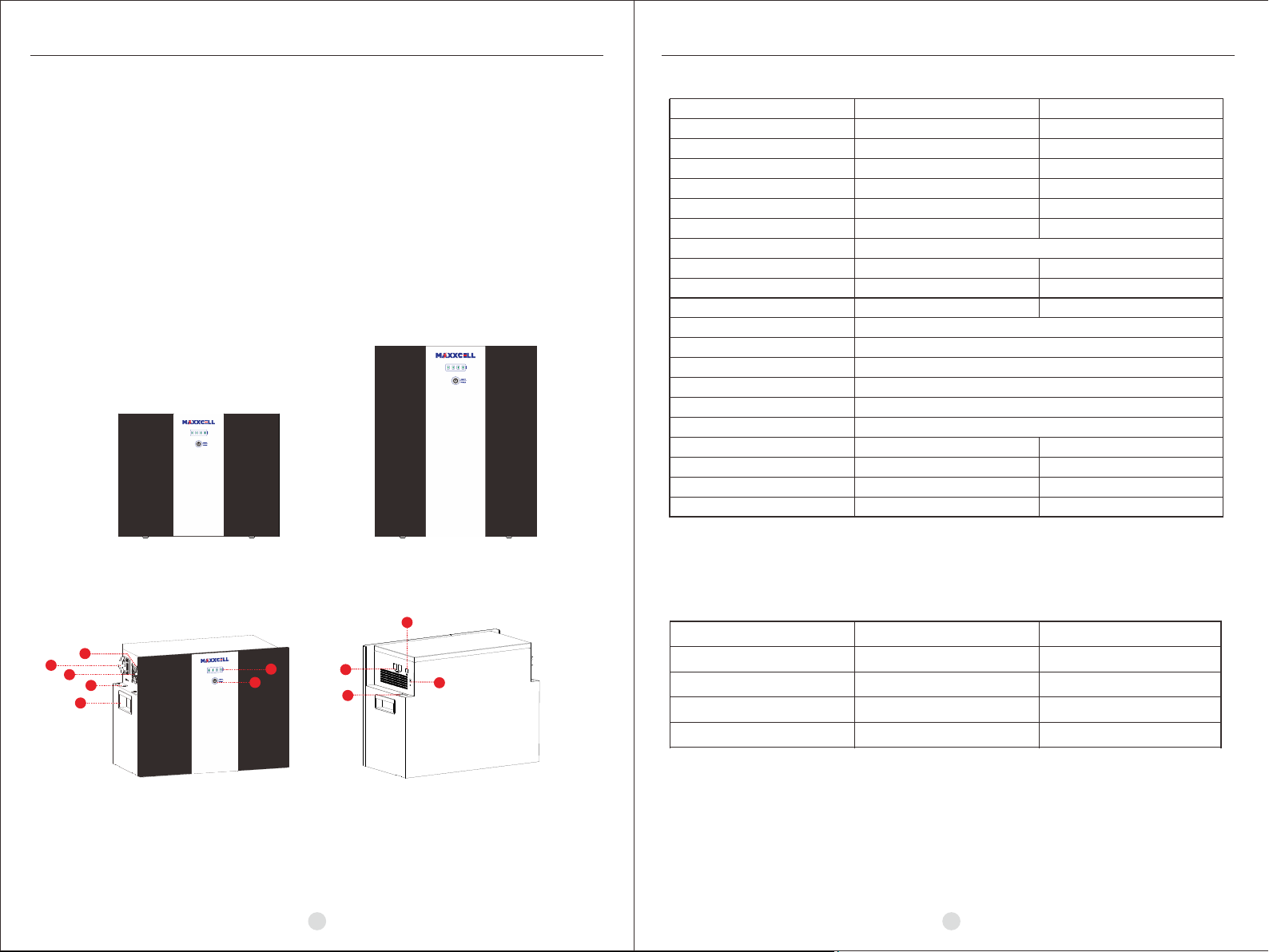
4.5 Description for KEY
constantly
light
constantly
light
LED1 Low power: LED
red light flash 1
Low power: LED red
light flash 1
Charing mode / off flash
4
Display according to SOC etc. ratio LED1 Low power: LED
red light flash 1
LED1 Low power: LED
red light flash 1
Sw1 SW2 SW3 SW4 Remarks
0 0 0 0 means ID=0,communication address is0x00/0x10③
1 0 0 0 means ID=1,communication address is0x01④
0 1 0 0 means ID=2,communication address is0x02
1 1 0 0 means ID=3,communication address is0x03
0 0 1 0 means ID=4,communication address is0x04
1 0 1 0 means ID=5,communication address is0x05
0 1 1 0 means ID=6,communication address is0x06
1 1 1 0 means ID=7,communication address is0x07
0 0 0 1 means ID=8,communication address is0x08
1 0 0 1 means ID=9,communication address is0x09
0 1 0 1 means ID=10,communication address is0x0A
1 1 0 1 means ID=11,communication address is0x0B
0 0 1 1 means ID=12,communication address is0x0C
1 0 1 1 means ID=13,communication address is0x0D
0 1 1 1 means ID=14,communication address is0x0E
1 1 1 1 means ID=15,communication address is0x0F
DIP switch SW5 Description②
SW5
1
0
Remarks
means disconnect
120Ω resistor
means connect
120Ω resistor
Remark①: 1 in SW1-SW5 indicates ON status, and 0 indicates OFF status.
Remark②: When multiple battery packs communicate, the last battery pack SW5 needs to be in the ON
status, otherwise the communication may have interference.
Remark③: When the battery pack ID is set to 0, it means stand-alone operation, and it is not necessary to
detect whether the parallel condition is satisfied ⑤
Remark④: When the battery pack ID is set to 1-15, it means that the parallel operation is required, and it is
necessary to detect whether the parallel condition is satisfied ⑤
Remark⑤: The parallel condition is that the difference between the battery voltage of the local battery and
all the battery pack voltages is <3V, otherwise wait until the condition is satisfied
DIP switch SW1-SW4 Description ①
4.4 DIP switch SW1-SW4 Description
08
5.5 Warranty
Limitation of Liability
www.maxxcell.com.au
This manual suits for next models
1
Table of contents
Other MAXXCELL Camera Accessories manuals