MAXXCELL LiFePO4 User manual

USER GUIDE
LiFePO4 Battery System for Households
358-010029-01 12-150MAX
8.8.8
88
NO.
SYNC
BATCELL MAXMIN
DISCHARGING
kWH
kAH
%
V C
ERROR
EQ
C

1 ABOUT THIS MANUAL .................................................................................... 1
1.1 Purpose ................................................................................................ 1
1.2 Scope ................................................................................................... 1
1.3 Safety Instructions ................................................................................. 1
2 INTRODUCTION ............................................................................................. 2
2.1 Features................................................................................................ 2
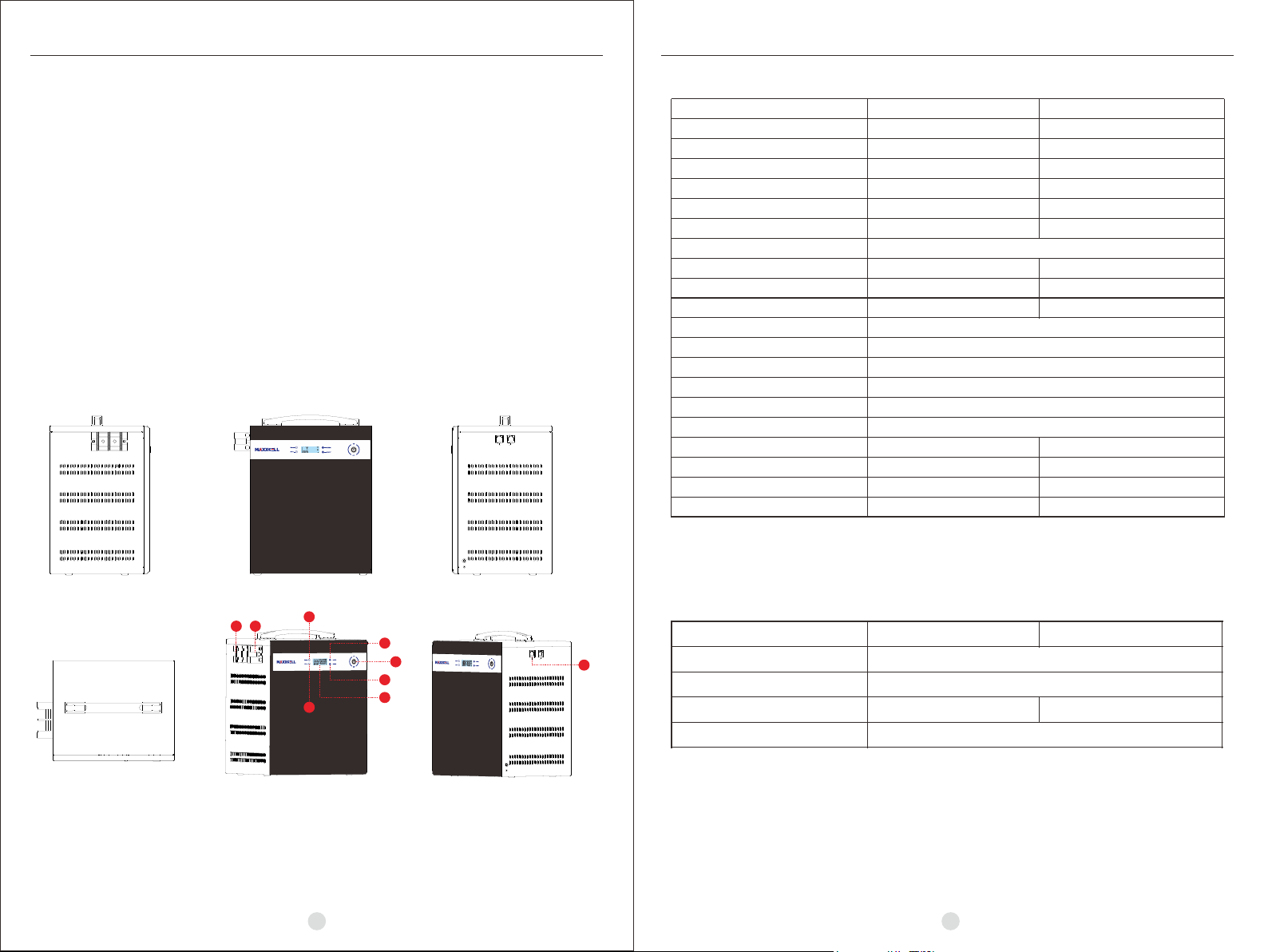
2.2 Product Overview .................................................................................. 2
2.3 Specifications ....................................................................................... 3
2.4 Recommended Settings ......................................................................... 3
3. INSTALLATION .............................................................................................. 4
3.1 Unpacking and Inspection ...................................................................... 4
3.2 Mounting the Unit .................................................................................. 4
3.3 Connection for Parallel Mode .................................................................. 5
4. OPERATION .................................................................................................. 6
4.1 Operation and Display Panel.................................................................... 7
4.2 LCD Display Icons ................................................................................. 7
5. LCD SETTING ................................................................................................ 9
6. DISPLAY INFORMATION ................................................................................ 10
7. OPERATING MODE DESCRIPTION ................................................................. 11
8. TROUBLESHOOTING..................................................................................... 12
8.1 Fault Code Table.................................................................................... 12
8.2 Warning Code Table ............................................................................... 12
9. EMERGENCY SITUATIONS ............................................................................ 13
9.1 Fire ...................................................................................... . ... . . .......... 13
9.2 Leaking Batteries .................................................................... .... . .. ....... 13
9.3 Wet Batteries ......................................................................................... 13
9.4 Warranty ............................................................................ . . . ................ 13
Contents
1.1 Purpose
This manual describes the introduction, installation, operation and emergency situations of the battery bank.
Please read this manual carefully before installations and operation. Keep this manual for future reference
1.2 Scope
This manual provides safety and installation guidelines as well as information on tools and wiring.
1.3 Safety Instructions
WARNING: This chapter contains important safety and operating instructions. Read and keep this
manual for future reference
1.Before using the unit, read all instructions and cautionary markings on the unit, the batteries and all
appropriate sections of this manual.
2. CAUTION –-- To reduce the risk of injury or damage, please use according to the instructions in this manual
3. Do not disassemble the battery. Take it to a qualified service centre when service or repair is required.
Incorrect re-assembly may result in a risk of fire.
4. To reduce risk of electric shock, disconnect all wires before attempting any maintenance or cleaning.
Turning off the unit will not reduce this risk.
5. CAUTION – Only qualified personnel can install this device with inverter.
6. For optimum operation of this battery, please follow required specification to select appropriate cable size.
7. Be very cautious when working with metal tools on or around batteries. Dropping tools onto the battery
has the potential to cause a short which could cause a fire. Please strictly follow installation procedure.
8. To support a full output load, at least 2 sets of 24V batteries for inverters larger than 3KVA, and at least 2
sets of 48V batteries for inverters larger than 5KVA should be used in parallel.
9. GROUNDING INSTRUCTIONS - This system should be connected to a permanent grounded wiring
system. Be sure to comply with local requirements.
10. NEVER cause AC output and DC input to short circuit. Do not connect to the mains when DC input short
circuits.
11. Warning!! Only qualified service persons are able to service this device.
12. Battery should be installed indoors and kept away from water, high temperature, mechanical force force
and flames.
13. Do not install the battery in temperatures below 0°C or over 45°C,and humidity over 80%.
14. Do not put any heavy objects on the battery.
1 ABOUT THIS MANUAL
01
LiFePO4 Battery System for Households
Special Attention: It is strongly recommended to stop using the load when
the battery pack is over-discharged. The battery pack should not be repeatedly force
activated for discharge or you may damage the battery cells reducing their life span.
If the battery pack is low and the internal BMS failsafe has activated you must
charge the battery immediately. If you do not you may need to use the AC or PV
activation method to wake the battery. Doing so will reduce the lifespan of your pack
The batteries cannot be charged with PWM controllers for charging

02 03
LiFePO4 Battery System for HouseholdsLiFePO4 Battery System for Households
2. INTRODUCTION
Purpose built solar and wind energy storage battery pack. Designed for simple 2 wire installation without the
complexity of Inverter and battery BMS compatibility.
• Iron phosphate-lithium power battery
• Long warranty period:5 years
• High energy density, compact in size
• Photovoltaic system: This battery pack is designed for household and commercial
photovoltaic/wind systems.
• Battery management system (BMS): The battery packs built-in BMS monitors its
operation and prevents the battery from operating outside design limitations.
• Expandability: This battery pack can be easily expanded by adding expansion battery packs
in parallel connection.
2.1 Features
2.2 Product Over View
POS + NEG -
COMM
1. ON / OFF 2. UP/ESC 3. DN/ENT
4. LED Display 5. STATUS 6. ALARM
7. Battery Negative - 8. Battery Positive + 9. Communication port
9
COMM
2.3 Specifications
2.4 Recommended Settings
Lithium battery packs are not the same as Lead Acid batteries. Ensure settings are specific to your battery pack
as the use of Lead Acid charging profiles on Lithium packs is dangerous.
Model
Usable Capacity
Voltage
Nominal Voltage
Voltage Range
Recommend Charge Cut-off Voltage
Recommend Discharge Cut-off Voltage
MAX. Charge & Discharge Current
Recommend Charge & Discharge Current
MAX. Output Power
Recommend Output Power
DOD
Modules Connection
Communication
Ingress Protection
Cycle Life
Working Temperature Range
Net Weight(KG)
Gross Weight(KG)
Product Dimension(MM)
Package Dimension(MM)
12-150MAX 12-200MAX
2KWH 2.5KWH
12 12
12.8 12.8
12-14.4 12-14.4
14.4 14.4
12 12
120A
≤60A ≤80A
1500W 1500W
750W 1000W
≥95%
1~6in parallel
RS485
IP21
≥3000 @25°C
Discharge:-20°C to +65°C, Charge:+0°C to +55°C
19.2KG 19.5KG
20.9KG 21.2KG
282*232*346.5MM 282*232*346.5MM
393*318*419MM 393*318*419MM
Setting
Max. Charging Voltage
Floating charging Voltage
Max. Charging Current
Cut-off voltage
Notes: “N” means the number of battery packs connected in parallel.
12-150MAX 12-200MAX
14.4V
14.4V
60A*N 80A*N
12V
8.8.8
88
NO.
SYNC
BATCELL MAXMIN
DISCHARGING
kWH
kAH
%
V C
ERROR
EQ
C
78
NEG -
POS +
1
2
3
4
5
6

04 05
LiFePO4 Battery System for HouseholdsLiFePO4 Battery System for Households
Before installation, please inspect the unit. Make sure that nothing inside the package is damaged. You
should have received the following items inside of package.
3.1 Unpacking and Inspection
3.2 Mounting the Unit
Consider the following points before selecting where to install:
• Do not mount the battery on flammable construction materials.
• The ambient temperature should be between 0°C and 45°C to
ensure optimal operation.
• The recommended installation position is to be mounted to the
wall vertically.
• Be sure to keep other objects and surfaces as shown in the right
diagram to guarantee sufficient heat dissipation and to have enough
space for removing wires.
3. INSTALLATION
NO NAME SPECIFICATION PICTURE
Communication line 1
Cables Used for battery parallel connection
Adapter
Screw Mounting screw
PV Wake up line
User manual User manual
2
4
3
1
1
4
5
6
3
2
Grid activation communication wire
( used with 6)
Used for activating the pack when grid
power recover
5
Used for auto restart when PV comeback
in off-grid system
Please follow below steps to implement battery connection:
1.Assemble battery ring terminal based on recommended battery cable and terminal size.
2.To support full output load, 1 set of 12-150MAX /12-200MAX batteries for inverters larger than 1KVA,
and at least 2 sets of 12-150MAX /12-200MAX batteries for inverters larger than 2KVA should be
used in parallel.
Note: if you need the battery to wake-up when grid power returns, connect the battery with grid use
power adapter and communication line 1 shown in the package list.
The battery supports parallel connection for capacity expansion. Connect parallel
batteries as displayed below.
3.3 Connection for Parallel Mode
Note: After select the positive and negative poles of one of the battery packs to output (the upper battery pack or
the lower battery pack, you can not select the positive and negative poles of the two battery packs at the same time).
After confirming the correct connection of the inverter, controller and batteries, you can switch any battery on and
the battery bank is ready for use.
NEG -
POS + NEG -
POS + NEG -
POS +
186mm
186mm
390.5mm
8.8.8
88
NO.
SYNC
BATCELL MAXMIN
DISCHARGING
kWH
kAH
%
V C
ERROR
EQ
C
8.8.8
88
NO.
SYNC
BATCELL MAXMIN
DISCHARGING
kWH
kAH
%
V C
ERROR
EQ
C
8.8.8
88
NO.
SYNC
BATCELL MAXMIN
DISCHARGING
kWH
kAH
%
V C
ERROR
EQ
C
8.8.8
88
NO.
SYNC
BATCELL MAXMIN
DISCHARGING
kWH
kAH
%
V C
ERROR
EQ
C
6

06 07
LiFePO4 Battery System for Households LiFePO4 Battery System for Households
Once the batteries are connected correctly, simply press the On/Off button to enable the output of the battery pack.
Note: A maximum of 6 batteries, connected in parallel is permitted
For pure off grid systems, the PV awake wire needs to be connected with an MPPT charge controller if the
battery pack is charged by solar panels only . The connection diagram is shown as below :
The Operation and display panel, shown in the below chart, is on the front panel of the battery pack.
It includes two LED indicators, two function keys, ON/OFF key and a LCD display indicating the operating
status and power information
4.1 Operation and Display Panel
LED Indicator
Solid On The battery pack is discharging.
Flashing The battery pack is charging.
Solid On Fault occurs in the battery pack.
Flashing Warning condition occurs in the battery pack.
Green
Red
LED Indicator Messages
STATUS
ALARM
Function Keys
Short press To go to last selection.
Press and hold To exit setting mode.
Short press To go to next selection.
Press and hold To confirm the selection in setting mode or enter setting mode.
Function Key Description
UP/ESC
DN/ENT
4.2 LCD Display Icons
8.8.8
88
NO.
SYNC
BATCELL MAXMIN
DISCHARGING
kWH
kAH
%
V C
ERROR
EQ
C
Icon Function description
Indicates the battery pack information.
Indicate the battery pack voltage,current.
Battery Pack Information
BAT
8.8.8
BAT
kWH
kAH
%
V C
4. OPERATION
8.8.8
88
NO.
SYNC
BATCELL MAXMIN
DISCHARGING
kWH
kAH
%
V C
ERROR
EQ
C
8.8.8
88
NO.
SYNC
BATCELL MAXMIN
DISCHARGING
kWH
kAH
%
V C
ERROR
EQ
C
8.8.8
88
NO.
SYNC
BATCELL MAXMIN
DISCHARGING
kWH
kAH
%
V C
ERROR
EQ
C
8.8.8
88
NO.
SYNC
BATCELL MAXMIN
DISCHARGING
kWH
kAH
%
V C
ERROR
EQ
C
8.8.8
88
NO.
SYNC
BATCELL MAXMIN
DISCHARGING
kWH
kAH
%
V C
ERROR
EQ
C
8.8.8
88
NO.
SYNC
BATCELL MAXMIN
DISCHARGING
kWH
kAH
%
V C
ERROR
EQ
C
COMM
8.8.8
88
NO.
SYNC
BATCELL MAXMIN
DISCHARGING
kWH
kAH
%
V C
ERROR
EQ
C
COMM
8.8.8
88
NO.
SYNC
BATC ELL M AXM IN
DISCHARGING
kWH
kAH
%
V C
ERROR
EQ
C
ON
OFF
UP/ESC
DN/ENT
LED Display
STATUS
ALARM

LiFePO4 Battery System for HouseholdsLiFePO4 Battery System for Households
Icon Function description
Indicates the battery cell information.
Battery Cell Information
Indicate the battery cell maximum voltage, minimum voltage, maximum
temperature, minimum temperature, every cell voltage, every cell
temperature.
Indicates the battery pack is charging.
Indicates the battery pack is discharging.
Indicates the battery pack charge MOS is switch on.
Indicates the battery pack discharge MOS is switch on.
Indicates the battery pack is balancing.
Indicates the setting programs.
Indicates the warning and fault codes.
Warning: flashing with warning code.
Fault: lighting with fault code.
8.8.8
CELL MAXMIN
kWH
kAH
%
V C
CELL
88
88
ERROR
88
NO.
Indicates the cell number.
CHARGING
DISCHARGING
EQ
Communication Sign
RS485 is connected and communication is successful.
Bluetooth is connected and communication is successful.
C
Configuration Program, Fault Information and Cell Number
Mode Operation Information
5. LCD Setting
Press and hold the “DN/ENT” to enter Settings mode, Press the “DN/ENT”or “UP/ESC” button to select Settings
Program required. Then, press and hold “DN/ENT” button to confirm the selection. “UP/ESC” button to exit.
Setting items:
Program
Description Selectable option
Exit setting
mode
00 ESC
Pack Type
Automatic identification of the
battery pack type, and can not
be set.
Escape
NULL
00
F
P
150
200
12-150MAX
12-200MAX
01
10 Balance Mode A L
P
Cell balance default is enable.
E
Cell balance is disable.
I5
P
11 Fault Record F
Fault record default is enable
Fault record is disable
1 day(default)
Address is 1(default)
1
If the battery is not charging or
discharging, turn it off after a day,
the options are 1H, 2H, 4H, 8H,
12H, 1d, 3d, 7d, 30d.
P
1
12 Sleep Countdown 5 lP
20 Communication
Address A
P P
Communication address
range is 1-30
Backlight Disable
Backlight Mode
21 L
P
Backlight Enable(default)
Return to default
display screen (default)
If selected, no matter how users
switch display screen, it will
automatically return to default
display screen (SOC) after 1
minute of inactivity.
Keep lastest screen
Auto return to
default display
screen
22
ef
P
If selected, the display screen
will stay at latest screen user
finally switches.
5
P
P
E P
0 1
0 1
0 1
1 0 1 0
1 0
1 1
1 1
E
I5
P
1 1
1 2 1 2
20 20
2 1
2 1
E
I5
P
2 1
22
22
22
08 09
Title

LiFePO4 Battery System for HouseholdsLiFePO4 Battery System for Households
6. Display Information
The LCD displays battery details as per the below table. To change the LCD information displayed,
press the“DN/ENT”or “UP/ESC”key.
Selectable information LCD display
SOC
SOC = 100%
Battery Voltage
Battery Current
1 0 0
%
Battery Voltage = 12.8V
12.8
V
BAT
Battery Current = 0A
0
BAT
A
Maximum Cell Voltage
Maximum Cell Voltage = 3.60V
3.60
CELL MAX
V
Minimum Cell Voltage
Minimum Cell Voltage = 3.00V
3.00
CELL MIN
V
Maximum Cell Temperature
Maximum Cell Temperature = 45℃
CELL MAX
45
℃
No.1 Cell Voltage
No.1 Cell Voltage = 3.20V
3.20
V
CELL
0 1
NO.
No.3 Cell Voltage
No.3 Cell Voltage = 3.20V
No.4 Cell Voltage
No.1 Cell Temperature
No.1 Cell Temperature = 25℃
25
℃
CELL
3.20
V
CELL
No.3 Cell Voltage = 3.20V
3.20
V
CELL
7. Operating Mode Description
Operation Mode Description LCD Display
Standby Mode No output is supplied by battery pack, and can
not charge in this mode
8 0
%
Normal Mode
The battery can be charged or discharged,
at this moment, it is charging.
The battery can be charged or discharged, at
this moment, it is discharging.
8 0
%
CHARG ING
8 0
%
DISCH ARGIN G
Overdischarge Mode In this mode, the battery is forbidden to discharge,
but can be charged.
8 0
%
CHARG ING
In this mode, the battery is forbidden to charge,
but can be discharged.
8 0
%
DISCH ARGIN G
Overcharge Mode
Errors are caused by inside circuit error or external
reasons such as high temperature, output short
circuit etc
8 0
%
Fault Mode
2 1
ERROR
10 11
03
NO.
04
NO.
0 1
NO.
Minimum Cell Temperature
Minimum Cell Temperature = 5℃
CELL MIN
5
℃
Software Version
Software Version = 1.00
100
5
No.2 Cell Voltage
No.1 Cell Voltage = 3.20V
3.20
V
CELL
02
NO.
The battery can be charged or discharged, at
this moment, there is no charge and no
discharge.
8 0
%

LiFePO4 Battery System for HouseholdsLiFePO4 Battery System for Households
13
9. EMERGENCY SITUATIONS
9.1 Fire
In case of fire, make sure that the following equipment is available near the battery system
• DC and AC Isolation switches
• NOVEC 1230, FM-200, or dioxide extinguisher
Batteries may explode when heated above 150°C. KEEP AWAY from the battery if it catches fire.
If the battery pack leaks electrolyte, avoid contact with the leaking liquid or gas. If there has been a leakage
and contact has been made:
• Inhalation: Evacuate the contaminated area, and seek urgent medical attention.
• Contact with eyes: Rinse eyes with running water for 5 minutes, and seek urgent medical attention.
• Contact with skin: Wash the affected area thoroughly with soap and water, and seek urgent medical attention.
• Ingestion: Induce vomiting, and seek urgent medical attention.
If the battery pack is wet or submerged in water isolate immediately and restrict all access. Contact your
supplier for assistance.
Damaged batteries are not fit for use, dangerous and must be handled with the utmost care. It may leak
electrolyte or produce flammable gas. If the battery pack seems to be damaged, pack it in its original
container, and then return it to your supplier.
Products that are operated strictly in accordance with the user manual are covered by the warranty within the
first 5 years from the date of purchase. Any violation of this manual may void the warranty.
Limitation of Liability
Any product damage or property loss caused by the following conditions, MaxxCell does not assume any direct
or indirect liability.
• Product modified, design changed or parts replaced.
• Changed, or attempted repairs and erasing of series number or seals;
• System design and installation are not in compliance with standards and regulations;
• The product has been improperly stored in owner\user’s premises;
• Transport damage (including painting scratch caused by movement inside packaging during shipping). A
claim should be made directly with the shipping or insurance company.
9.2 Leaking Batteries
9.3 Wet Batteries
9.4 Warranty
12
8.1 Fault Code Table
Fault Code Fault Information
01 Battery voltage is too high.
02 Battery voltage is too low.
03 Charge current is too high.
04 Discharge current is too high.
05 Cell voltage is too high.
06 Cell voltage is too low.
07 Cell temperature is too high.
08 Cell temperature is too low.
09 MOS temperature is too high.
11 Sample sensor is abnormal.
8.2 Warning Code Table
Warning Code Warning Information
23 Charge current is high.
24 Discharge current is high.
27 Cell temperature is high for charge.
28 Cell temperature is low for charge.
35 Cell voltage difference is too large.
8. Troubleshooting
9.4 Damaged Batteries
Table of contents
Other MAXXCELL Camera Accessories manuals