Component Testing Procedures
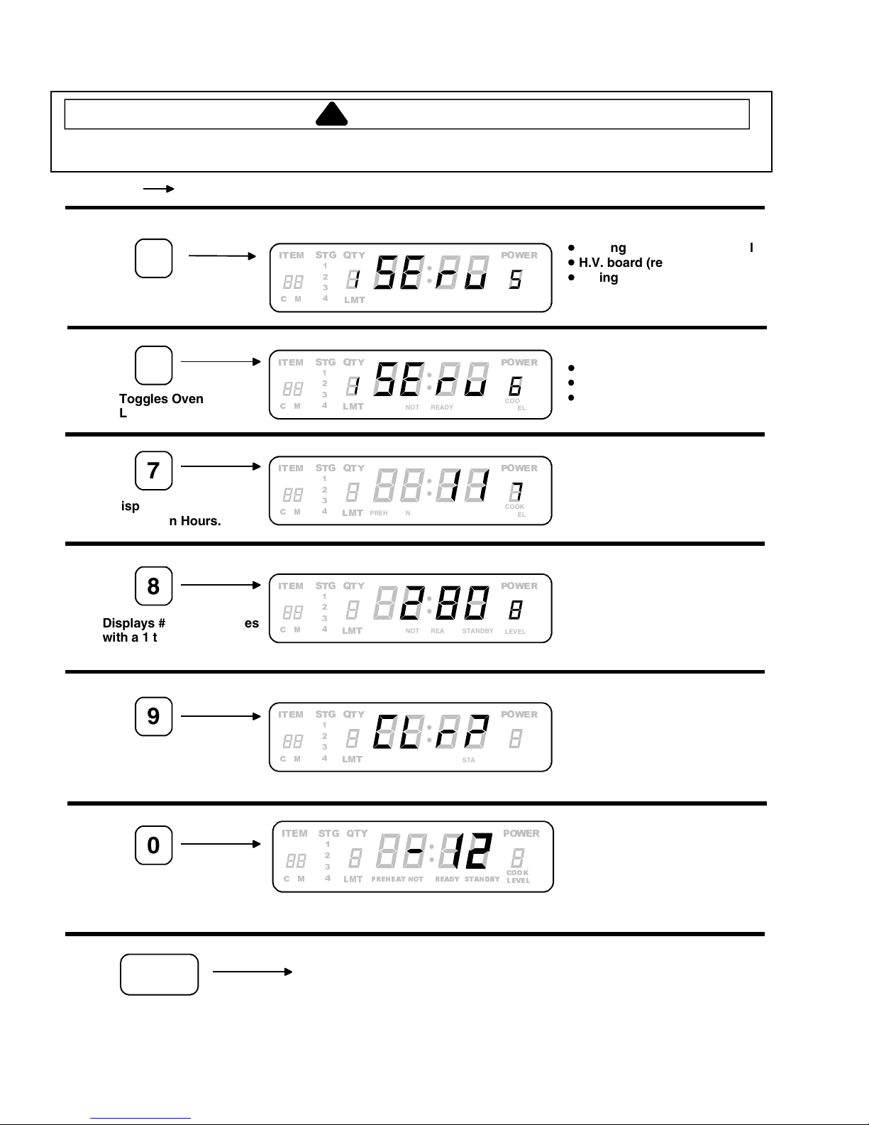
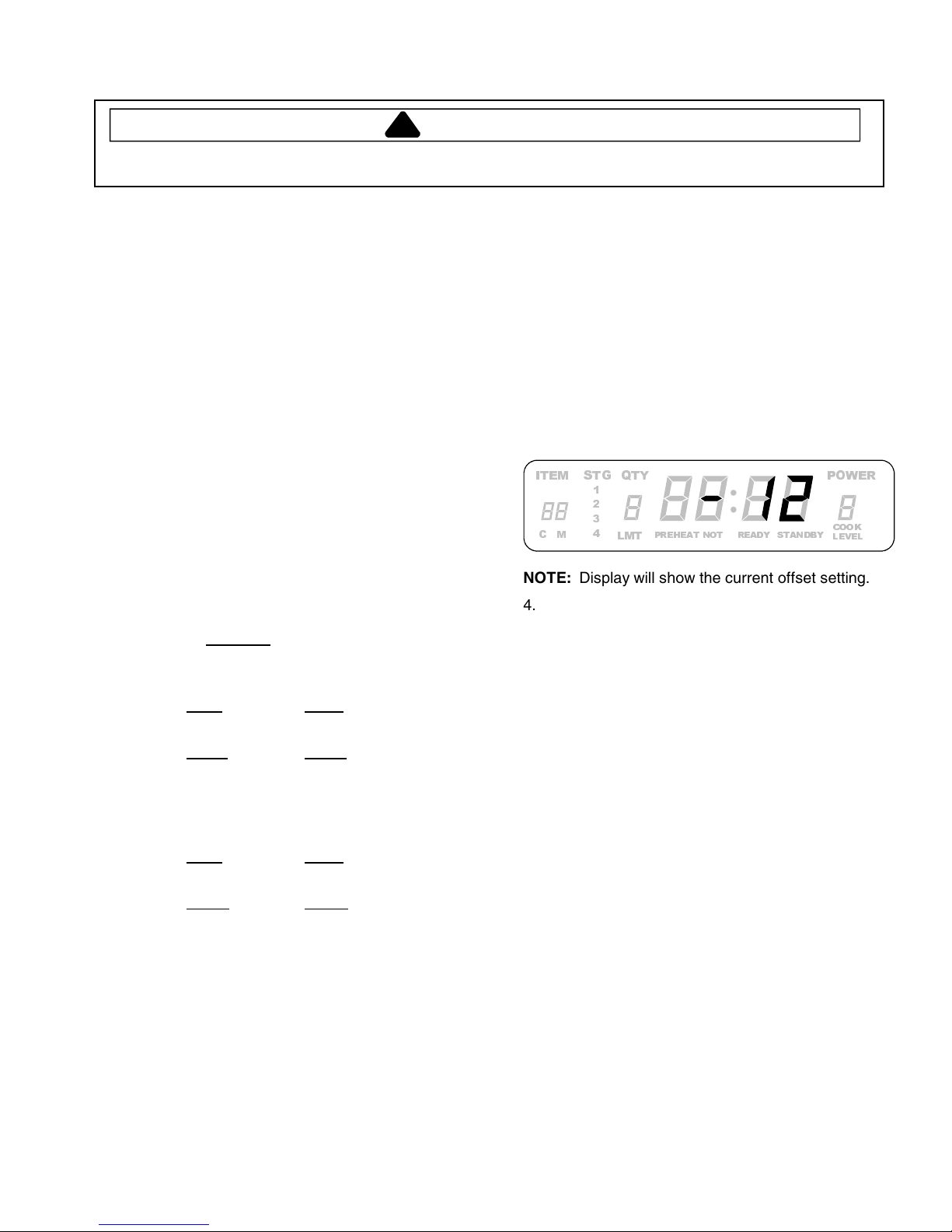
!
WARNING
To avoid risk of electrical shock, personal injury or death; disconnect power to oven and discharge capacitor
before servicing, unless testing requires power.
16025975 March 2005
©2005 Maytag Services
2
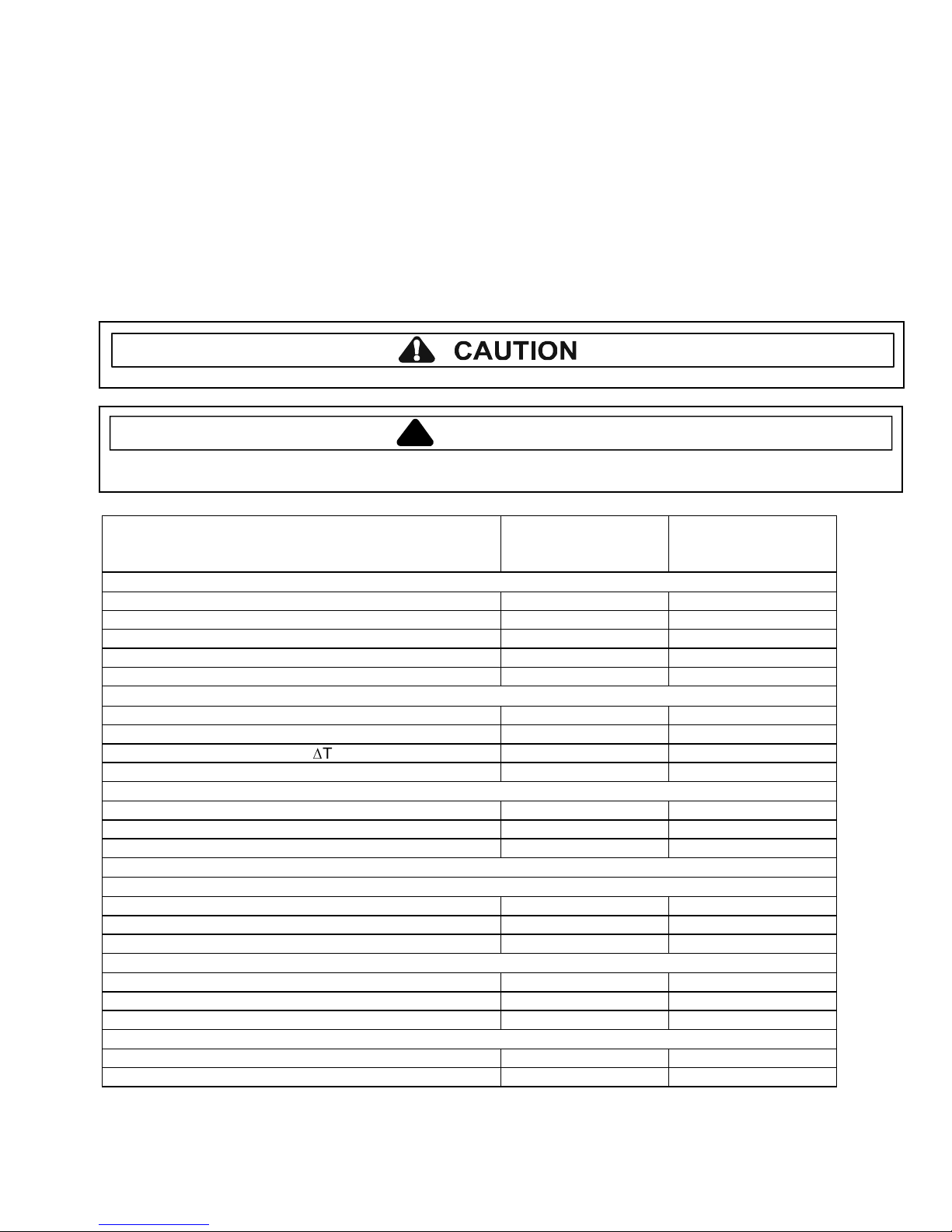
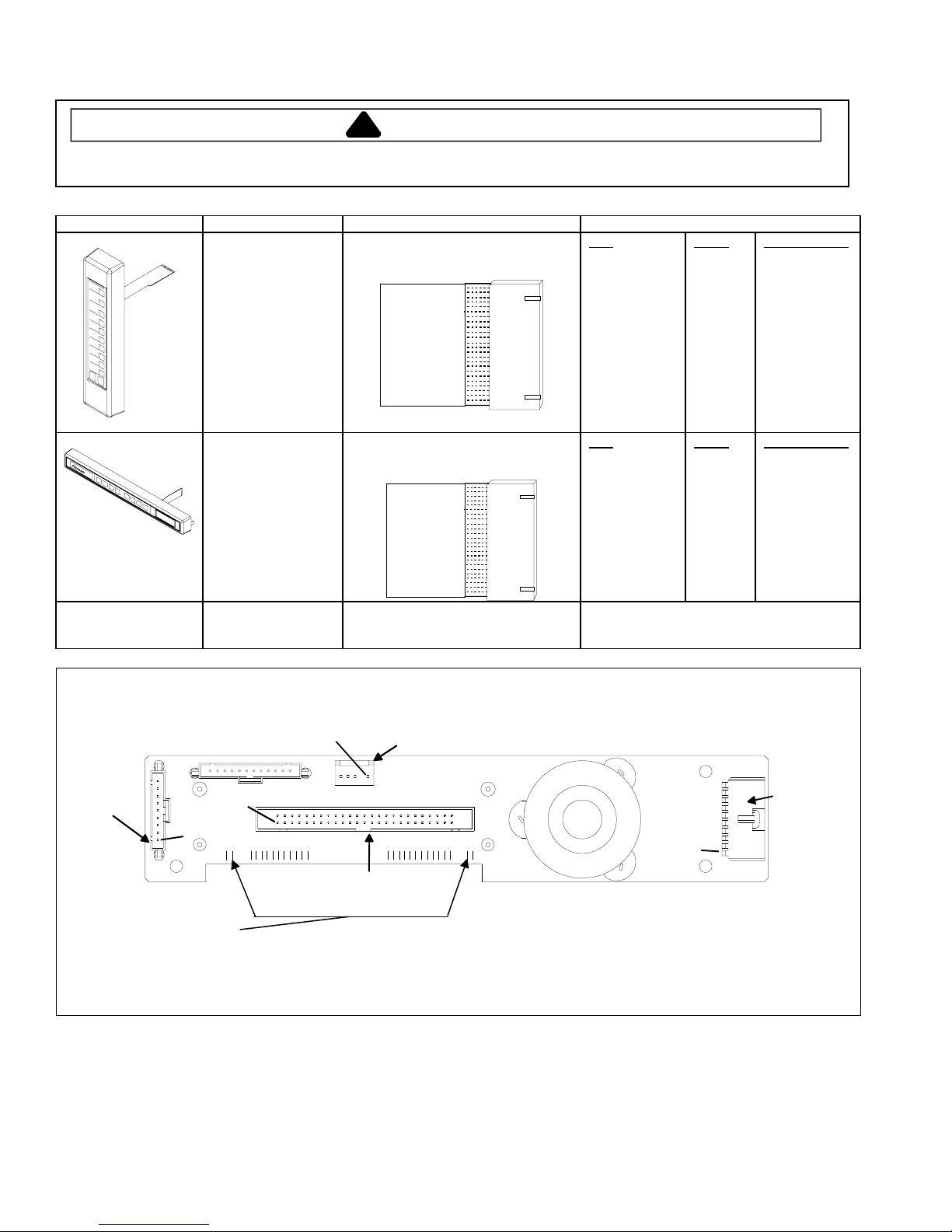
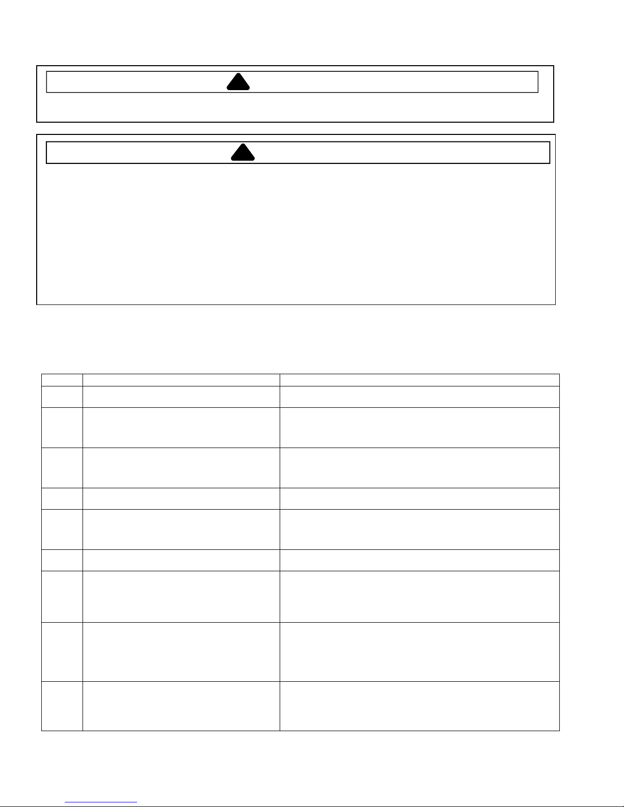
Illustration Component Test Results
Thermal cutout Disconnect all wires from TCO.
Measure resistance across terminals.
Control TCO..........................................
Fan TCO...............................................
Magnetron TCO ....................................
Heater Box Limiter ................................
Open at 300°F (149°C) and
closed at 257°F (125°C)
Open at 125°F (52°C) and
closed at 160°F (71°C )
Open at 235°F (113°C) and
closed at 150°F (66°C)
Open at 351°F (177°C) and
closed at or below 18°F (-8°C)
Diode Discharge Capacitor
Remove diode lead from capacitor and
connect ohmmeter.
Reverse leads for second test.
Infinite resistance should be measured
in one direction and 50KΩor more in
the opposite direction.
NOTE: Ohmmeter must contain a
battery of 6 volts minimum.
MT2
MT1 GATE
Triac Disconnect wires to triac.
Measure resistance from:
MT1 to MT2 ..........................................
MT1 to Gate..........................................
MT2 to Gate..........................................
All terminals to ground ..........................
Caution - Do not operate oven with
wire to terminal MT2 removed.
Infinite
Approximately 15 Ω, then reverse
meter leads 30 Ω
Infinite
Infinite
Triac 1 (top) is for front element
Triac 2 (middle) is for rear element
Triac 3 (bottom) is for microwave
Measure voltage from:
MT1 to Gate
0.8 VAC when energized. If no
voltage, check H.V. board and wiring.
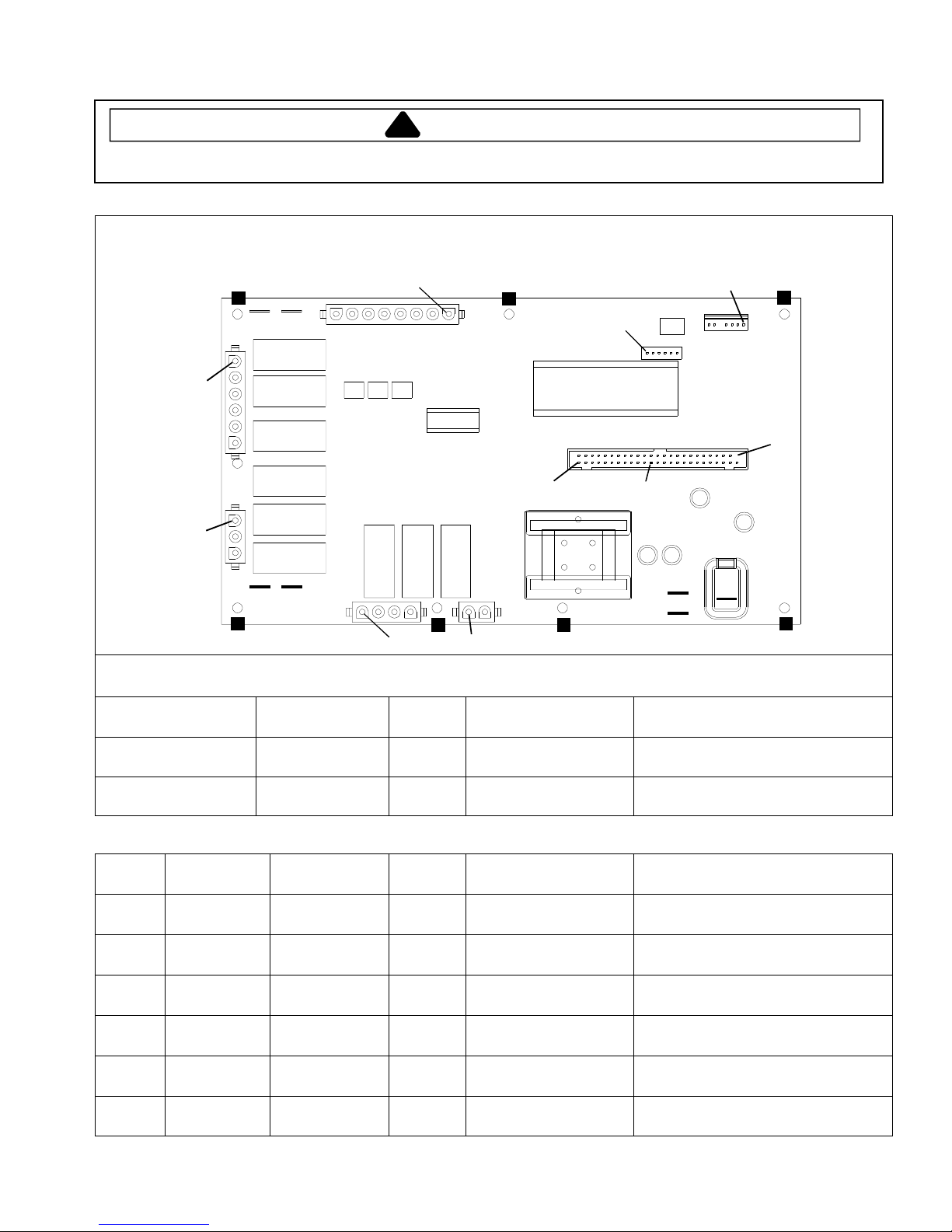
Capacitor Discharge Capacitor
Remove wires from capacitor terminals and
connect ohmmeter, set on highest
resistance scale to terminals.
Also check between each terminal and
capacitor case.
Between Terminals: Meter should
momentarily deflect towards zero then
return to over 5 MΩ. If no deflection
occurs, or if continuous deflection
occurs, replace capacitor.
Terminal to Case: Infinite resistance
Snubber assembly Disconnect wires to snubber.
Measure resistance across terminals.
Infinite
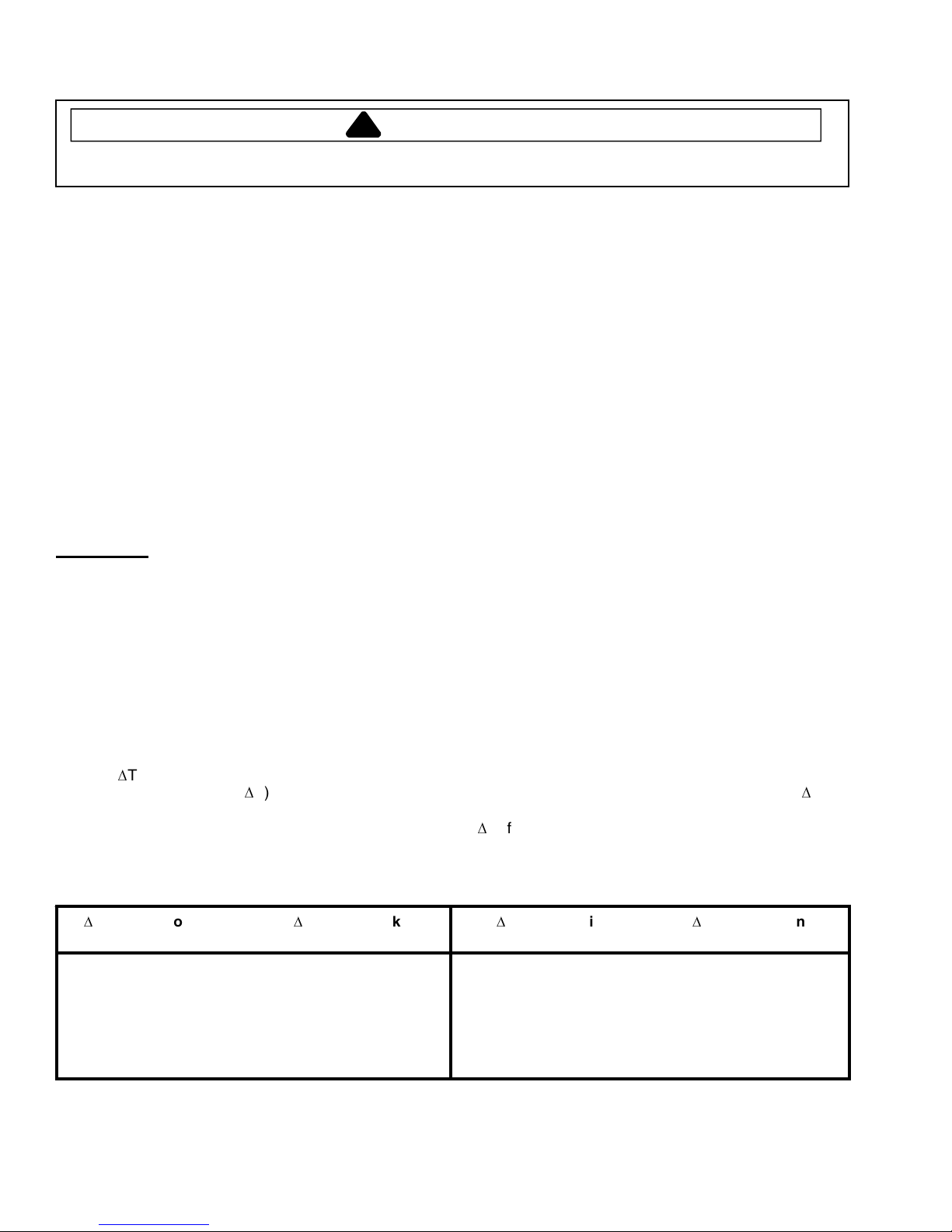
Magnetron Discharge Capacitor
Remove wires from magnetron and connect
ohmmeter to terminals. Also check
between each terminal and ground.
Between Terminals: Less than 1 Ω
Each terminal to ground measures
Infinite resistance.
Note: This test is not conclusive. If
oven does not heat and all other
components test good replace the
magnetron and retest.
Microwave blower
motor
Remove all wires from motor.
Measure resistance across coil.
Approximately 30 Ω


 Operating and installation instructions")