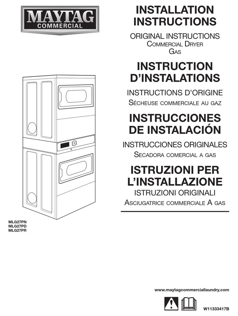
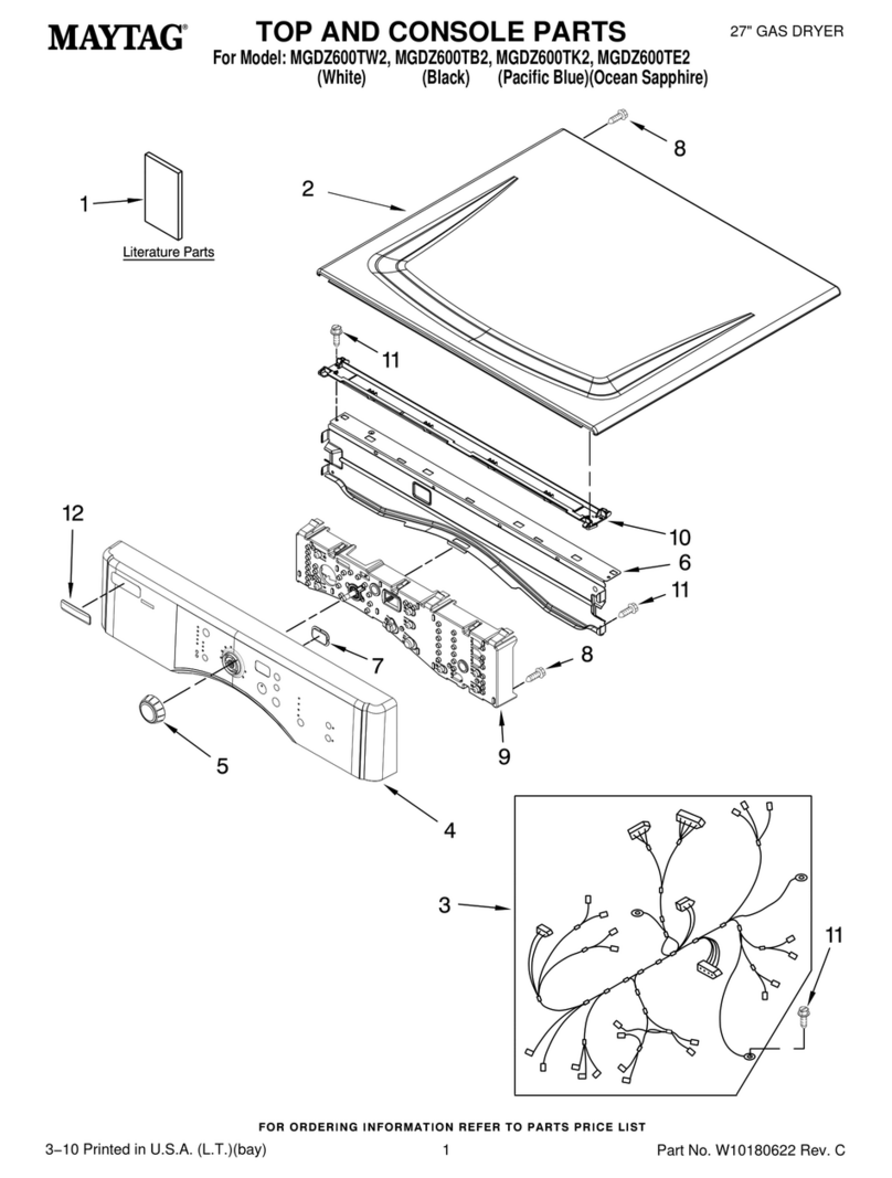
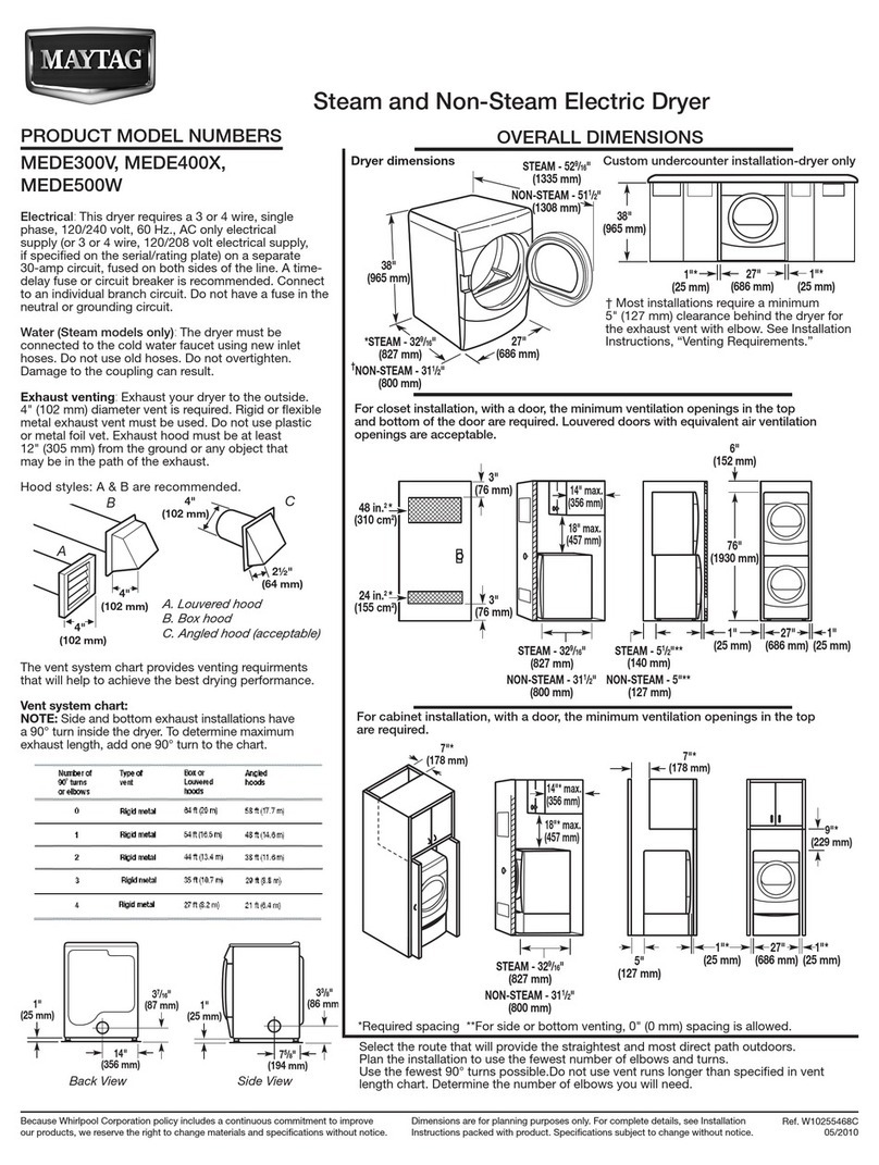
Maytag MLG33 Manual

Service Procedures
for the
Model MLG33 Dryer
Hot Surface Ignitor Gas
Part No. 450266-2
Whirlpool Corporation
CommercialLaundry
BentonHarbor,MI 49022
1-800-662-3587

“IMPORTANT NOTE TO PURCHASER”
Information must be obtained from your local gas supplier on the
instructionstobefollowediftheusersmellsgas. Theseinstructions
mustbepostedinaprominent location near the dryer.
FOR YOUR SAFETY
Do not store or use gasoline
orotherflammablevapors
andliquidsinthevicinity of
thisoranyotherappliance.
POUR VOTRE SÉCURITÉ
Ne pas entreposer ni utiliser d’essence
nid’autresvapeursou liquides
inflammablesà proximité de cet
appareiloude tout autre appareil.
Wehave tried to make this manual ascomplete as possible and hope you willfind it useful. The manufacturer
reserves the right to make changes from time to time, without notice or obligation, in prices, specifications,
colors, and material, and to change or discontinue models. The illustrations included in this manual may not
depict your particular dryer exactly.
IMPORTANT
For your convenience, log the following information:
DATEOFPURCHASE _____________________________________________________ MODELNO. ____________________
DISTRIBUTOR’S NAME ___________________________________________________________________________________
SERIAL NUMBER(S) ______________________________________________________________________________________
_______________________________________________________________________________________________________
_______________________________________________________________________________________________________
For replacement parts, contact the distributor from which the dryer was purchased or contact:
Whirlpool Corporation
Commercial Laundry
BentonHarbor, MI49022
1-800-662-3587
Retain This Manual in a Safe Place for Future Reference
This product embodies advanced concepts in engineering, design, and safety. If this product is properly
maintained, it will provide many years of safe, efficient, and trouble free operation.
Only qualified technicians should service this equipment.
OBSERVE ALL SAFETY PRECAUTIONS displayed on the equipment or specified in the installation
manual included with the dryer.
The following “FOR YOUR SAFETY” caution must be posted near the dryer in a prominent location.
MLG33

Table of Contents
Part Locations and Removal ................4
LowerFrontPanel Removal ......................................... 4
UpperFrontPanel Removal ......................................... 4
TopCoverRemoval....................................................... 4
MiddlePanelRemoval.................................................. 4
LintBox/BlowerAssemblyRemoval............................. 5
GasValve/Ignition SystemRemoval............................. 5
OvenChamberRemoval ............................................... 6
GasValve/Ignition System Components ...................... 6
OvenHousing Components.......................................... 6
TumblerSupport
WheelAssembly Replacement .................................... 6
TumblerAlignment ....................................................... 7
BeltReplacement ........................................................ 8
Placing the Belt Back on the Motor Sheave................. 8
Electrical Component Locations..........9
Electrical Panel ........................................................... 9
Sail Switch andAxial ProbeAssembly ........................ 9
Exhaust Probe, Exhaust Hi-limit,
andLintDrawerSwitch ................................................ 9
IMPORTANT
You must disconnect and lockout the electric
supply and the gas supply or the steam supply
before any covers or guards are removed from
the machine to allow access for cleaning,
adjusting,installation,ortestingofanyequipment
per OSHA (Occupational Safety and Health
Administration)standards.
Please observe all safety precautions
displayed on the equipment and/or specified in
theinstallationmanualincluded with thedryer.
CAUTION
Dryer(s)should never beleftunattendedwhilein
operation.
“Caution: Label all wires prior to disconnection
whenservicingcontrols. Wiringerrorscancause
improperoperation.”
«Attention: Lor des opérations d’entretien des
commandes étiqueter tous fils avant de les
déconnecter. Toute erreur de câblage peut étre
unesourcede danger et de panne.»
WARNING
Childrenshould notbeallowedto playonornear
thedryer(s). Childrenshouldbesupervisedifnear
dryer(s)inoperation.
Under no circumstances should the dryer door
switch(es), lint door/drawer switch(es), or heat
safetycircuit(s)ever be disabled.
Thedryermustnever beoperatedwithanyofthe
back guards, outer tops, or service panels
removed. Personalinjury or fire could result.
Thedryermustnever beoperatedwithoutthelint
filter/screen in place, even if an external lint
collectionsystemisused.
FOR YOUR SAFETY
Donotdrymopheadsinthedryer. Donotuse
dryerinthepresenceofdrycleaningfumes.
The dryers must not be installed or stored in
an area where it will be exposed to water
and/orweather.
The wiring diagram for the dryer is located in
thefront electrical control box area.

4 MaytagCo. 450266-2
Part Locations and Removal
UPPER FRONT PANEL REMOVAL:
Remove the four screws located just above the top
loading door. Tilt the bottom of the panel out and lift
the panel up and away from the dryer.
LOWER FRONT PANEL REMOVAL:
Remove the lint drawer. Remove the four screws
located just below the loading door. Tilt the top of
thepanel out and lift thepanel up and away fromthe
dryer.
TOP COVER REMOVAL:
Firstremovethe back guard,thefour screws holding
top cover. Next pull top cover toward the rear of the
dryer and lift up.
MIDDLE PANEL REMOVAL:
Remove the four screws along bottom of panel.
Next, remove four screws along top of panel.
Tilt the top of the panel out, disconnect electrical
connectionto computerpanel, liftpanel andunhook
support brackets.

450266-2 MaytagCo. 5
Unplug two connections on the exhaust hi-limit at
theleftofthelintbox. The lint box maynowbepulled
out through the front of the dryer.
Unplug the motor harness.
Remove two screws just above the lint drawer and
pull the lint box down from the front and out slightly.
Unplug the exhaust temperature probe.
LINT BOX/BLOWER ASSEMBLY REMOVAL:
EXHAUST
HI-LIMIT
To remove motorizedimpellor assembly, remove lint
housing cover, lint screen, and the four screws
shown with arrows. Pull the motorized impellor
assembly out through the opening.
GAS VALVE/IGNITION SYSTEM REMOVAL:
Be sure to shut off the gas main and then proceed
to remove electrical connections and screws
indicated. Remove lower front panel. Disconnect
union and screws noted with arrows.
Thegasvalveandburnerorificecannowbecarefully
pulled toward the front of the dryer.
Be sure to pull the assembly straight back so as not
to strike the very fragile carbon ignitor. With the
assembly partly out of the oven, the ignitor and the
two gas valve electrical connections can be
disconnected. At this point the assembly can be
removed from the dryer.
Replace assembly in the reverse order but make
sure the tab at the rear of the assembly engages
into the oven base slot.
Inspect all wires to be sure all lead directly toward
the front of the dryer. Be sure no wires are caught
on the burner tube or ignitor.

6 MaytagCo. 450266-2
TUMBLER SUPPORT
WHEEL ASSEMBLY REPLACEMENT:
The front wheel assemblies can be replaced with
the lower front panel removed. Remove the three
bolts by reaching upward with a socket or box
wrench. The illustration below is provided to show
the location of these wheels as the wheels cannot
easily be seen while standing in front of the dryer.
The left rear wheel assembly can be removed with
just the back guard removed. The rear right wheel
requires removing the back guard, heat duct, and
oven. Be sure to mark the position of rear wheel
brackets prior to removal (refer to page 7).
OVEN CHAMBER REMOVAL:
The oven chamber can be removed after the gas
valve/ignition system has been removed.
Remove the two screws indicated by the arrows.
Pull the oven housing part way out through the front
and disconnect all wire connections. The oven
housing can now be removed.
Replace assembly by leading the housing cone into
the hole in the rear wall. Replace screws and wire
connections.
GAS VALVE/IGNITION SYSTEM COMPONENTS:
BURNERTUBE
IGNITOR
GAS VALVE
OVEN HOUSING COMPONENTS:
HEAT SENSOR
OVENCHAMBER
BURNERHIGH-LIMIT

450266-2 MaytagCo. 7
TUMBLER ALIGNMENT:
Proper alignment is achieved by making the gap
between the tumbler and openings in the front and
rear bulkheads equal on all sides.
The front to bulkhead may be checked for accuracy
by using a thickness gauge. The rear gap is not
accessible. Marking the position of the rear wheel
brackets before removing the brackets will help in
replacing the tumbler back into it’s original position
when the wheel brackets are reinstalled.
Adjust the tumbler position by loosening the three
bolts and forcing the wheel assembly toward the
center of the dryer to raise the tumbler and to move
it away from the side. A large screwdriver can
provide the necessary leverage. Adjustment of the
front of the tumbler is made by equalizing the gap
onthetop,bottom,leftandright bymovingthewheel
assemblies.
EXAMPLES:
Below, both wheel assemblies must be moved to
the right in order to move the tumbler right. The left
wheel assembly must move a little more than the
right in order to lift the tumbler.
Below, both wheel assemblies are adjusted correct
and spacing is even on all sides.
All wheel assemblies are mounted on slots to allow
foralignmentofthetumbler. After oneormorewheel
assemblies are replaced, the tumbler must be
realigned.

8 MaytagCo. 450266-2
BELT REPLACEMENT:
Shut off electrical power to the dryer. Lockout and
tagout supplyvoltages. Follow the steps to remove
front middle panel. Next you will remove either the
front bottom or front upper panel, depending on
pocket you are working on. Remove the belt from
the motor sheave. Next, remove the two screws
fastening the lint coupe to the front panel. Remove
the front panel screws, while holding up the
basket. Tilt the top of the front panel forward. Take
note of position of motor adjustment nut spin
counterclockwise to loosen tension. The old belt
can now be removed. Slide the new belt around
basket and push belt to a position close the motor
sheave.
FIG. 2
FIG. 1
FIG. 3
FIG. 4
PLACING THE BELT
BACK ON THE MOTOR SHEAVE:
Placebelt installation tool(BIT) over belt(Fig. 1) and
rotate in a clockwise direction. While rotating run
BIT under motor sheave (Fig. 2). Continue to spin
BIT, belt will then wrap under motor sheave (Fig. 3).
Remove BIT from dryer (Fig. 4). Next, you want to
rotate basket slowly to ensure it is on the sheave
completely. Tighten the motor adjustment nut to
position previous set.

450266-2 MaytagCo. 9
Electrical Component Locations
ROTATIONAL
SENSOR
DOOR SWITCH
COMPUTER
COVER
SAIL SWITCH AND AXIAL PROBE ASSEMBLY:
Located behind back guard. Access doors are
provided. Backguard does nothave to beremoved.
AXIAL PROBE
SAIL SWITCH
EXHAUST PROBE, EXHAUST HI-LIMIT,
AND LINT DRAWER SWITCH:
Temperature probe and exhaust hi-limit are
accessible without the lint box being removed. The
lint drawer switch can be removed after the lint box
is and the cover has been removed.
EXHAUST
HI-LIMIT
TEMPERATURE
PROBE
LINT DRAWER SWITCH
ELECTRICAL PANEL:
Theelectricalpanelislocatedbehindthefrontmiddle
panel.

Part No. 450266 2 - 06/10/14
Other manuals for MLG33
1
Table of contents
Other Maytag Dryer manuals

Maytag
Maytag MGD5830TW0 User manual

Maytag
Maytag MEDC700VJ0 User manual

Maytag
Maytag MGDE900VJ0 User manual

Maytag
Maytag 3405344 User manual

Maytag
Maytag MGDX655DW2 User manual

Maytag
Maytag MED8150EW User manual

Maytag
Maytag MGD6000X User manual

Maytag
Maytag SD-4 User manual

Maytag
Maytag MED6000X User manual

Maytag
Maytag NEPTUNE MD68 User manual

Maytag
Maytag ld9904 User manual

Maytag
Maytag MD9606 User manual

Maytag
Maytag MGDX5SPAW User manual

Maytag
Maytag MLG-45PDB User manual

Maytag
Maytag MGDE500VW2 User manual

Maytag
Maytag W10267633A User manual

Maytag
Maytag 4KMEDC100 User manual

Maytag
Maytag MLG31PCBWW User manual

Maytag
Maytag MEDE500VF0 User manual

Maytag
Maytag MEDB955FW User manual