113284-1 Maytag Co. 7
Installation Procedures ______________
!WARNING
Excessive Weight Hazard
Use two or more people and mechanical equipment
to lift, move and install dryer.
Failure to do so can result in back or other injury.
Installation should be performed by competent professional
in accordance with local, state, and country codes. In the
absence of these codes, the installation must conform to
applicable American National Standards: ANSI Z223.1-
LATEST EDITION (National Fuel Gas Code) or ANSI/NFPA
NO. 70-LATEST EDITION (National Electrical Code) or in
Canada, the installation must conform to applicable Canadian
Standards: CAN/CGA-B149.1-M91 (Natural Gas) or CAN/
CGA-B149.2-M91 (L.P. Gas) or LATEST EDITION (for
General Installation and Gas Plumbing) or Canadian
Electrical Codes Parts 1 & 2 CSA C22.1-1990 or LATEST
EDITION (for Electrical Connections).
Leveling Dryer
The dryer is equipped with 4 leveling legs, 1 at each corner
of the base. For optimum performance the dryer should be
level front-to-back and side-to-side.
Tools Required
■Utility Knife to remove packaging
■9/16”Box wrench or 9/16”socket to remove pallet bolts
■#2 Phillips screwdriver to open front toe panel
■Pipe wrench for gas connections
■7/8”open end wrench or adjustable wrench
to install coin box lock
■TORX®T20 TORX®T25 to open rear bottom guard
to get foot adjustment ends
■1/4”socket or 1/4”open end wrench to make the
leg adjustment
■A pair of slip-joint pliers
®TORX is a registered trademark of Textron Innovations, Inc.
Installing Door Handle
1. Remove handle from dryer tumbler.
2. Unwrap door handle from bubble wrap.
3. Locate handle standoff in the handle slots.
4. Insert 1/4-20 x 2-1/4”stainless Truss Head Phillips screws
through preexisting door holes.
5. Having handle flushed against door, tighten the two
stainless Phillips screws.
Location Requirements ______________
!WARNING
Explosion Hazard
Keep flammable materials and vapors, such as
gasoline, away from dryer.
Do not install in a garage.
Failure to do so can result in death, explosion, or
fire.
Before installing the dryer, be sure the location conforms to
local codes and ordinances. In the absence of such codes
or ordinances the location must conform with the National
Fuel Gas Code ANSI.Z223.1 LATEST EDITION, or in Canada,
the installation must conform to applicable Canadian
Standards: CAN/CGA-B149.1-M91 (Natural Gas) or
CAN/CGA-B149.2-M91 (L.P. Gas) or LATEST EDITION (for
General Installation and Gas Plumbing).
The operation of this dryer may affect the operation of other
types of gas dryers, which take their air for safe combustion
from the same room. If in doubt, consult the dryer
manufacturer(s).
The dryer must be installed on a sound level floor capable of
supporting its weight. Carpeting must be removed from the
floor area that the dryer is to rest on.
The dryer must not be installed or stored in an area where it
will be exposed to water and/or weather.
Provisions for adequate air supply must be provided as noted
in this manual (refer to Fresh Air Supply Requirements
section).
Clearance provisions must be made from combustible
construction as noted in this manual (refer to Dryer Enclosure
Requirements section).
Provisions must be made for adequate clearances for
servicing and for operation as noted in this manual (refer to
Dryer Enclosure Requirements section).
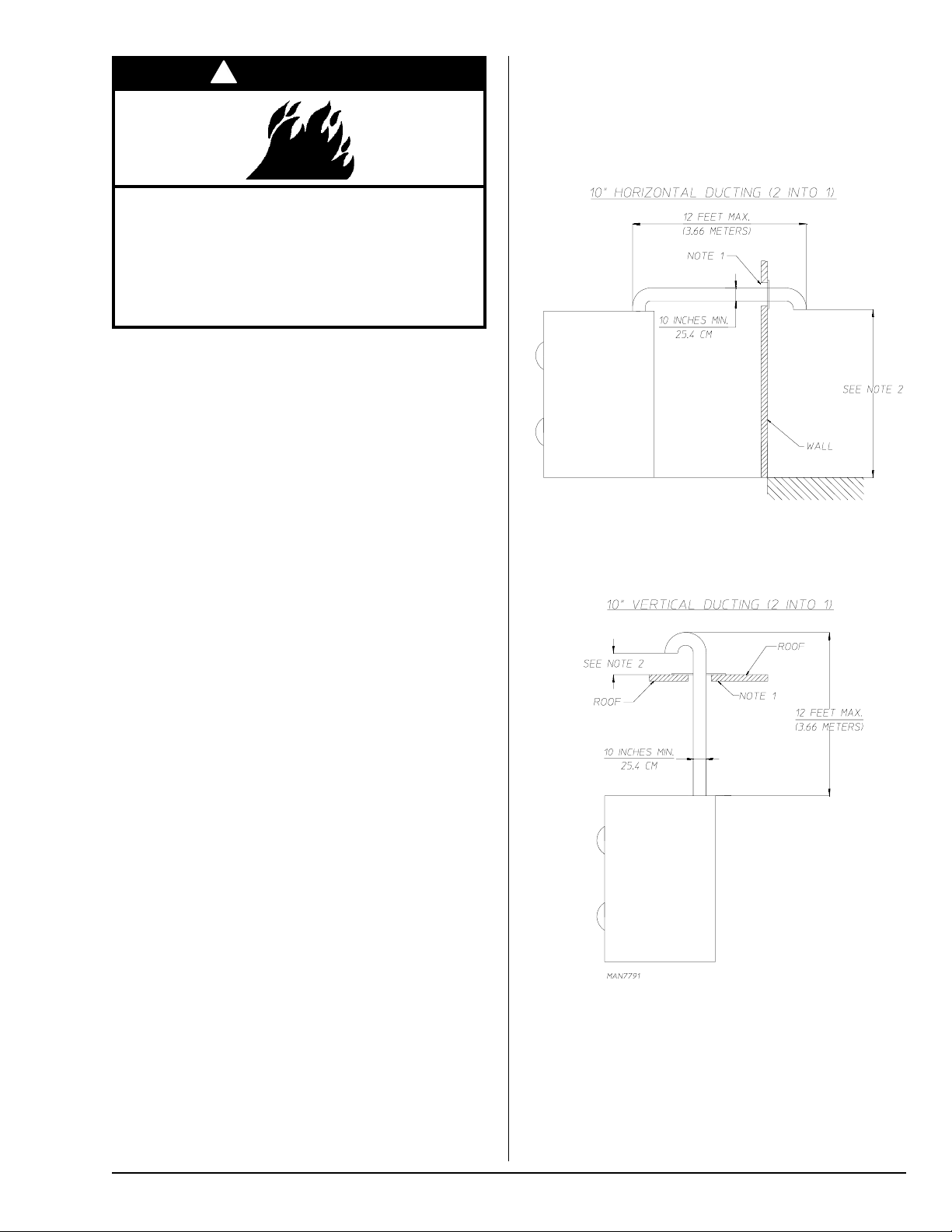
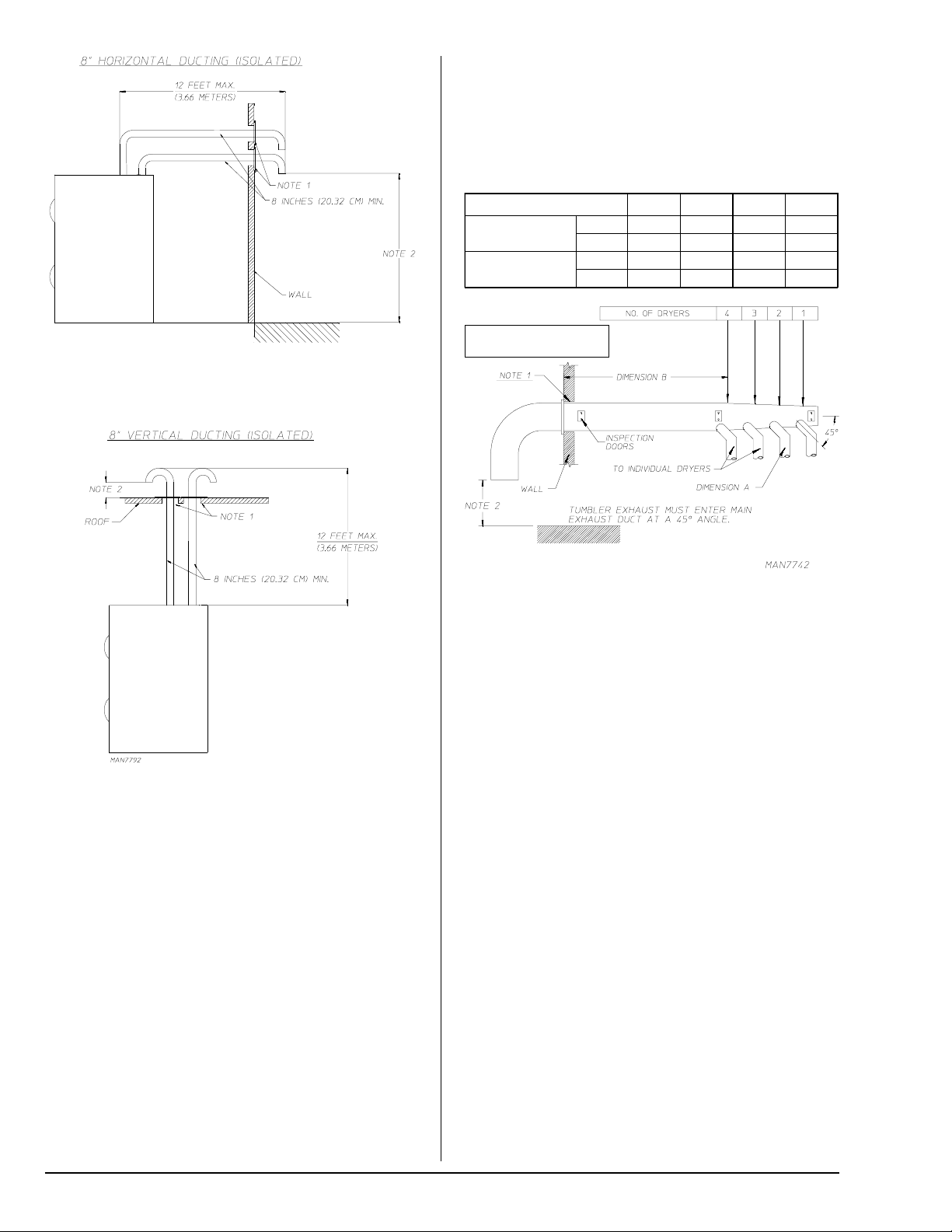
The dryer must be installed with a proper exhaust duct
connection to the outside as noted in this manual (refer to
Exhaust Requirements section).
The dryer must be located in an area where correct exhaust
venting can be achieved as noted in this manual (refer to
Exhaust Requirements section).
IMPORTANT: The dryer should be located where a
minimum amount of exhaust ducting will be necessary.
The dryer must be installed with adequate clearance for air
openings into the combustion chamber.
IMPORTANT: The dryer must be installed in a location/
environment, which the ambient temperature remains
between 40° F (4.44° C) and 130° F (54.44° C).