GENERAL INFORMATION
IMPORTANTINFORMATION
......................
GI- 2
.............................
BASIC ASSUMPTIONS GI- 2
SAFETY RISK
............................................
GI- 2
POSSIBLE LOSSOF WARRANTY
...........
GI- 2
WARNING ON LUBRICANTSAND
GREASES
................................................
GI- 2
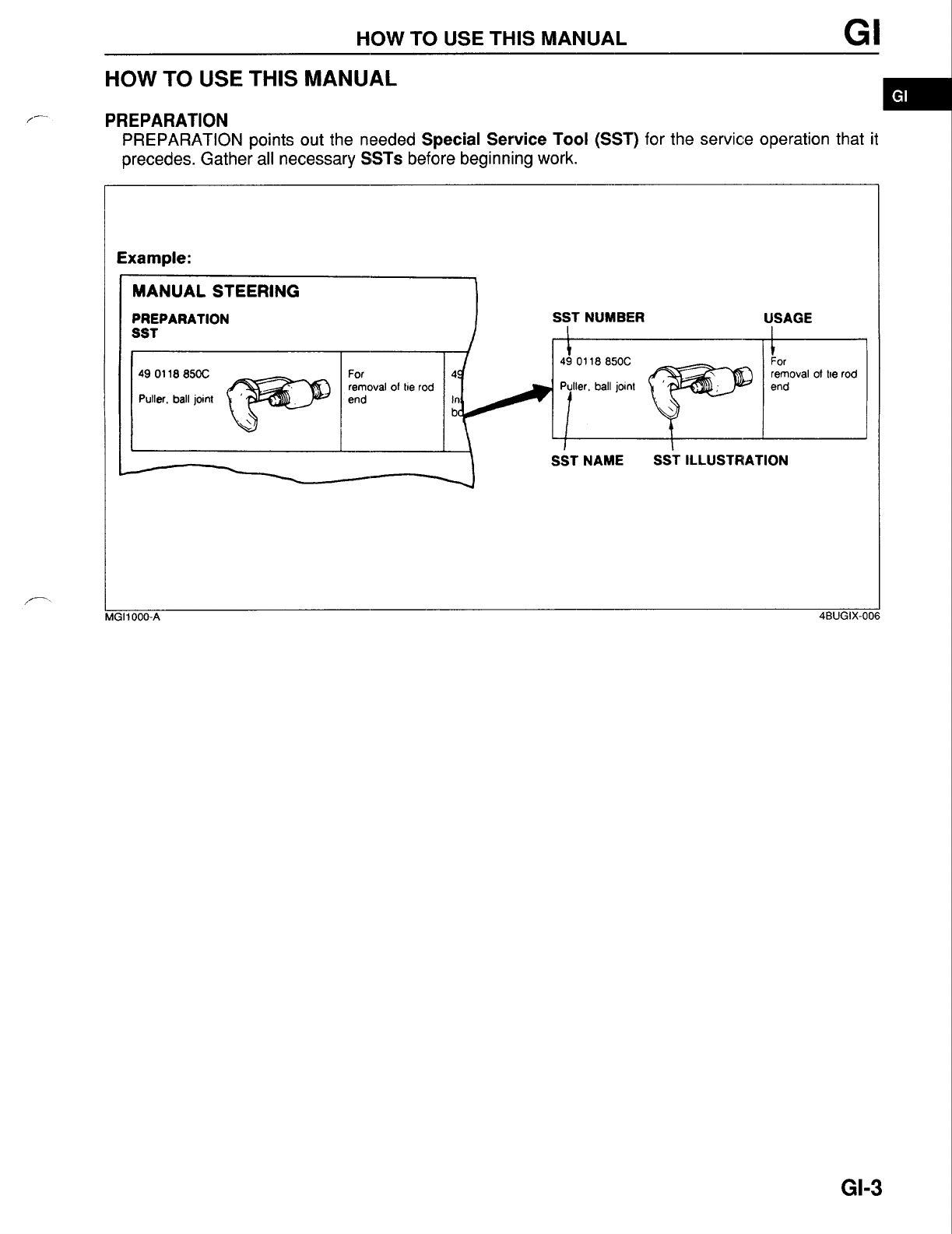
HOWTO1 USETHIS MANUAL
.....................
GI- 3
PREPARATION
.........................................
GI- 3
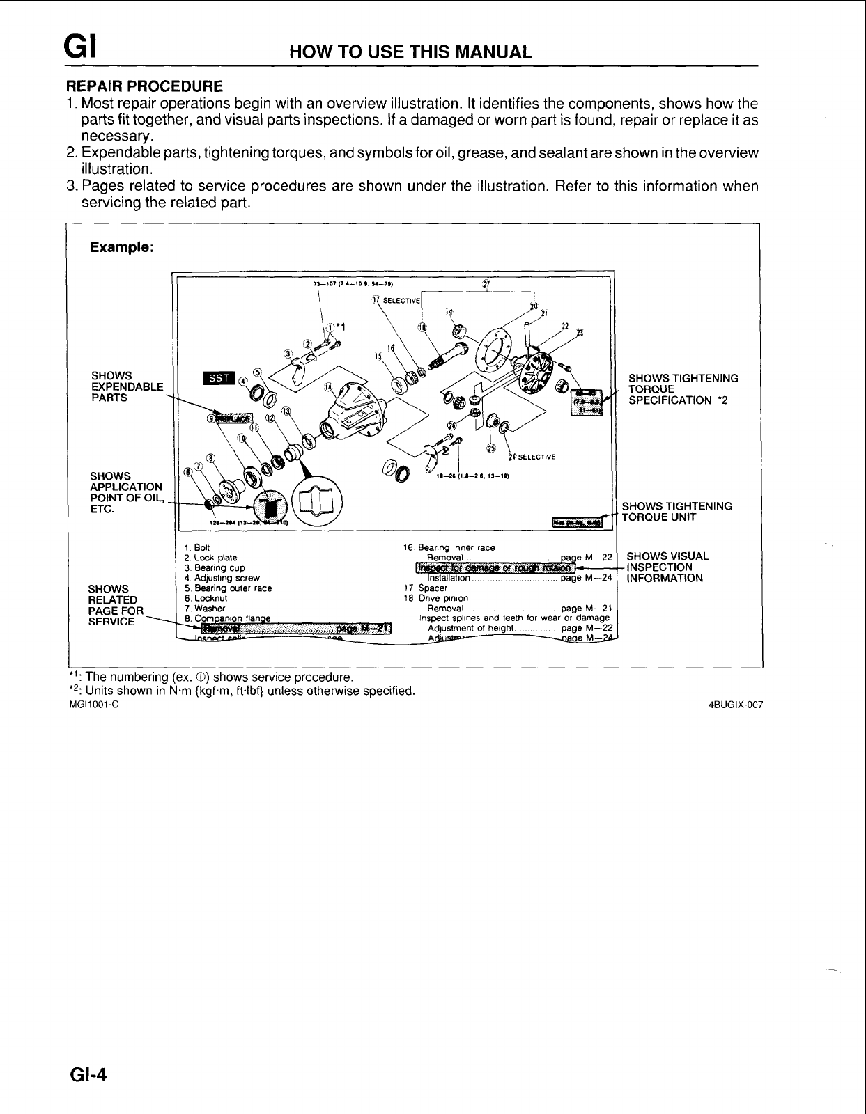
REPAIR PROCEDURE
..............................
GI- 4
SYMBOLS
..................................................
GI- 5
NOTES. CAUTIONS. AND WARNINGS
....
GI-
5
................
FUNDAMENTALPROCEDURES GI-
5
PROTECTIONOF THE VEHICLE
.............
GI- 5
........................
A WORD ABOUT SAFETY GI- 6
PREPARATIONOFTOOLSAND
MEASURING EQUIPMENT
.....................
GI- 6
.......................................
SPECIALTOOLS GI- 6
REMOVALOF PARTS
...............................
GI-
6
DISASSEMBLY
..........................................
GI- 6
ASSEMBLY
................................................
GI-
7
ADJUSTMENTS
.........................................
GI-
8
RUBBER PARTSAND TUBING
................
GI-
8
JACK AND SAFETY STAND(RIGID RACK)
POSITIONS
.................................................
GI-
9
..............................................
FRONT END GI-10
REAR END
.................................................
GI-10
VEHICLE LIFT(2-SUPPORTTYPE)
.................................................
POSITIONS GI-1
1
FRONT END
..............................................
GI-12
REAR END
...............................................
GI-12
.......................................................
TOWING GI-13
GENERAL TOWING PROCEDURE
PREPARATORYSTEPS
.........................
GI-13
TOWllVG TWO-WHEELDRIVE
...............................................
VEHICLES GI-13
TOWllVG FOUR-WHEEL DRIVE
VEHICLES
...............................................
GI-14
TOWllVG EQUIPMENT
..............................
GI-15
TOWllVG CONNECTIONS
.........................
GI-1
6
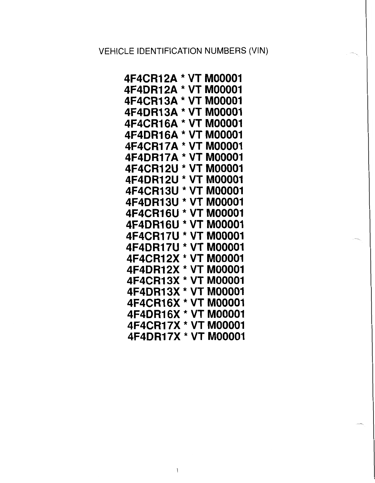
VEHICLE IDENTIFICATIONNUMBER
........
GI-17
SAFETY COMPLIANCECERTIFICATION
......................................................
LABELS GI-1
9
...........................................................
UNITS GI-23
ABBREVIATIONS
........................................
GI-23
SAE STANDARDNAME
..............................
GI-24
......................................................
CAUTION GI-26
ELECTRICALTROUBLESHOOTING
TOOLS
.....................................................
GI-26
.....
CAUTION WITH ELECTRICAL PARTS GI-27
4BUGIX-001