MBNLED DMX STRIP 30 User manual

MBNLED DMX STRIP 30
Bedienungsanleitung
User’s Guide
Rev. 1.1 07.05.2010

MBNLED DMX STRIP 30
info@mbnled.com www.mbnled.com
2
Inhalt
1. Hardware Setup ………………………………………………………………………. 2
2. Betrieb von bis zu 8 Strips …………………………………………………………. 4
3. Betrieb von mehr als 8 Strips mit AUX Power Eingang ………………………. 5
4. Inbetriebnahme und Software Setup ……………………………………………... 8
5. Fehlerbeseitigung …………..………………………………………………………. 10
1. Hardware Setup
Auf den folgenden Grafiken sind das Layout der Ober- und Unterseite des Strips
sowie die wesentlichen Funktionselemente dargestellt, deren Beschreibung in dieser
Anleitung mit eckigen Klammern gekennzeichnet ist (z.B. [2]).
Abb 1. Rückansicht des LED Strips
1. Eingangsstecker (weiß) für +24V DC und DMX Signal
2. Strombrücke (siehe später im Abschnitt über die Verwendung des AUX
Power Anschlusses)
3. AUX Power Eingang (siehe später im Abschnitt über die Verwendung
des AUX Power Anschlusses)
4. Ausgangsstecker (dunkelgrau) für +24V DC und DMX Signal

MBNLED DMX STRIP 30
info@mbnled.com www.mbnled.com
3
Abb. 2. Frontansicht des LED Strips
5. UP Taste
6. DOWN Taste
7. OK Taste
Bei jedem DMX Strip können mit drei Tasten folgende Funktionen selektiert werden:
SEGMENT NUMMER {15, 5, 3, oder 1}Anzahl der individuell steuerbaren RGB
Segmente.
DMX ADDRESSIERUNGS MODUS {Auto oder Manual}Modus zur Festlegung der
DMX Start Adresse.
DMX START ADDRESS {1bis 512}Wenn der Adressierungsmodus auf Manual
gesetzt ist,geben Sie hier die DMX Startadresse des Strips ein.
BEVOR SIE EINEN WEITEREN STRIP ANSCHLIESSEN, SCHALTEN SIE ALLE
STROMVERSORGUNGS- UND DMX- SIGNALQUELLEN AUS! AB- UND
ANSCHLUSS DARF NIEMALS UNTER STROM ERFOLGEN, ANDERENFALLS
KÖNNEN DIE STRIPS BESCHÄDIGT WERDEN!

MBNLED DMX STRIP 30
info@mbnled.com www.mbnled.com
4
2. Betrieb von bis zu 8 Strips
Die Grafik auf der linken Seite verdeutlicht den Anschluss
der maximal zulässigen Anzahl Strips ohne zusätzliche
AUX Stromversorgung. In diesem Fall beträgt die maximal
zulässige Anzahl hintereinander geschalteter Strips 8 Stück
(die Stromversorgung ist nur am ersten Strip
angeschlossen). Danach müssen Sie eine neue Reihe mit
einem weiteren Stromversorgungs-PCB beginnen oder den
AUX Power Anschluss verwenden (siehe nächste Seite).
ACHTEN SIE BESONDERS AUF EINEN KORREKTEN
ANSCHLUSS DER PCB’s. DER WEISSE STECKER IST
IMMER DER POWER/DMX EINGANG, DER
DUNKELGRAUE STECKER IST DER POWER/DMX
AUSGANG! BEI FALSCHEM ANSCHLUSS KANN DER
STRIP BESCHÄDIGT WERDEN! ACHTEN SIE
AUSSERDEM DARAUF, NICHT MEHR ALS ACHT STRIPS
IN EINER REIHE ANZUSCHLIESSEN (WENN NUR DER
ERSTE STRIP MIT SPANNUNG VERSORGT WIRD), DA
EINE ÜBERLASTUNG SOWOHL DIE STECKER ALS
AUCH DIE STRIPS BESCHÄDIGT!
Abb. 3. Betrieb von bis zu acht Strips

MBNLED DMX STRIP 30
info@mbnled.com www.mbnled.com
5
3. Betrieb von mehr als acht Strips
mit AUX Power Eingang
Die Grafik auf der linken Seite verdeutlicht den
Anschluss, wenn Sie mehr als acht Strips in
einer Reihe betreiben wollen. In diesem Fall
MUSS an den AUX Power Eingang des achten
Strips eine zusätzliche Stromversorgung
angeschlossen werden UND die beiden
Leitungsbrücken [2] auf der Rückseite des
achten Strips müssen durchtrennt werden.
Nach jedem achten Strip muss in gleicher
Weise eine zusätzliche AUX Power
Stromversorgung angeschossen werden.
Anmerkung: Die AUX Power Stromversorgung
kann dieselbe sein, mit der der erste Strip
versorgt wird, sofern die Leistung ausreichend
ist (jeder Strip benötigt 12W bei weißem Licht
mit voller Helligkeit). Somit ist lediglich eine
korrekte Verkabelung erforderlich.
ACHTEN SIE BESONDERS AUF EINEN
KORREKTEN ANSCHLUSS DER PCB’s. DER
WEISSE STECKER IST IMMER DER
POWER/DMX EINGANG, DER DUNKEL-
GRAUE STECKER IST DER POWER/DMX
AUSGANG! BEI FALSCHEM ANSCHLUSS
KANN DER STRIP BESCHÄDIGT WERDEN!
Abb. 4. Betrieb von mehr als acht Strips mit
AUX Power Stromversorgung

MBNLED DMX STRIP 30
info@mbnled.com www.mbnled.com
6
Abb. 5. Betrieb von mehr als acht Strips mit AUX Power Stromversorgungen
kombiniert Input/Output Power Boards

MBNLED DMX STRIP 30
info@mbnled.com www.mbnled.com
7
Die Grafik auf der vorigen Seite zeigt einen Anschluss, bei dem Input/Output Power
Boards zur Versorgung mit AUX Power Spannung eingesetzt werden. Am achten
Strip wird der AUX Power Input verwendet, um die neue Stromversorgung für die
weiteren Strips bereitzustellen, aber zwischen Strip 16 und Strip 17 wird die
Kombination aus Input und Output Power Boards eingesetzt, um die neue
Versorgungsspannung zuzuführen. Wie Sie sehen können, sind nur die DMX
Datenleitungen zwischen diesen Strips verbunden, die neue Stromversorgung erfolgt
hingegen über das Input Power Board.
Auf den folgenden Bildern sind einige Beispiele korrekter und falscher Verbindungen
zwischen den Strips zu sehen.
KORREKTE VERBINDUNG
FALSCHE VERBINDUNGEN

MBNLED DMX STRIP 30
info@mbnled.com www.mbnled.com
8
4. Inbetriebnahme und Software Setup
Wenn Sie die Installation der Strips abgeschlossen haben, führen Sie folgende
Schritte aus:
1. Schalten Sie das Netzteil ein.
2. Nach dem Einschalten leuchtet innerhalb von zwei Sekunden jedes erste
Segment der Strips GRÜN auf. Wenn es nicht oder ROT aufleuchtet, lesen
Sie die Fehlerbeschreibung in dieser Anleitung!
3. Die Werkseinstellung der DMX Strips ist wie folgt: DMX Adresse=001,
AutoDMXAddressierung=ON, SegmentNummer=15.Wenn Sie diese
Einstellung unverändert übernehmen wollen, fahren Sie mit Schritt 9 fort.
4. Um diese Einstellung zu modifizieren, drücken Sie die OK Taste [7] auf dem
Strip. (Die Modifikation muss für jedes Board separat durchgeführt werden; es
gibt keine Möglichkeit, die Einstellungen global für die gesamte Reihe
auszuführen!) Nach der Betätigung wird die DMX Adresse durch die LED’s in
binärer Form angezeigt (ROT bedeutet, das entsprechende Bit=0, GRÜN
bedeutet, das Bit=1).

MBNLED DMX STRIP 30
info@mbnled.com www.mbnled.com
9
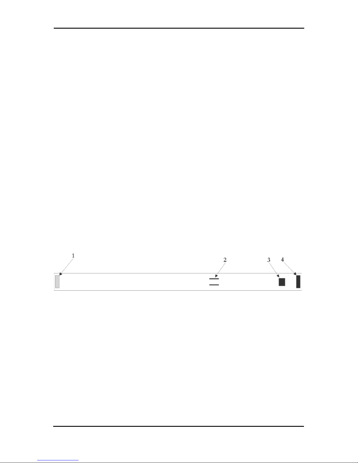
5. Um die Adresse zu verändern (MANUAL DMX Modus), drücken Sie die OK
Taste erneut. Jetzt leuchtet nur noch ein Segment (das 12.) ROT oder GRÜN
entsprechend der jeweiligen Einstellung. ROT bedeutet, der Strip befindet sich
im AUTO DMX Modus und GRÜN bedeutet, der Strip befindet sich im
MANUAL DMX Modus. Sie können diese Einstellung jetzt mit den UP / DOWN
Tasten [5,6] ändern. Drücken Sie dann die OK Taste [7], um die Einstellung zu
speichern.
Nach Betätigung der OK Taste [7] befinden Sie sich im SEGMENT Setup.
Wenn Sie diese Einstellung nicht verändern wollen, drücken Sie die OK Taste
[7] einfach noch einmal. Um die Einstellung zu ändern, wählen Sie mit den UP
/DOWN Tasten [5,6] die gewünschte Zahl Segmente (15, 5, 3 oder 1
Segment) aus. Drücken Sie OK, um die Einstellung zu speichern.
ACHTUNG! NACHDEM DIESE EINSTELLUNG MODIFIZIERT WURDE,
MÜSSEN SIE DIE STRIPS AUS- UND WIEDER EINSCHALTEN, DAMIT DIE
KORREKTEN DMX ADRESSEN ERNEUT BERECHNET WERDEN
KÖNNEN!
6. Nach Betätigung der OK Taste [7] leuchtet das erste Segment des Strips
GRÜN auf. Sollte es ROT leuchten, lesen Sie die Fehlerbeschreibung in
dieser Anleitung!
7. Wenn Sie die Einstellung von AUTO auf MANUELL geändert haben, müssen
Sie zurück zur Adresseneinstellung gehen. Drücken Sie hierzu die OK Taste
[7]. Mit den UP / DOWN Tasten [5,6] können Sie jetzt die gewünschte DMX
Adresse einstellen. Drücken Sie die OK Taste erneut, um die Einstellung
abzuspeichern. Drücken Sie danach noch zweimal die OK Taste, um zum
normalen Betrieb zurückzukehren (Sie überspringen damit den zweiten und
dritten Setup Schritt).
8. Schalten Sie die DMX Signalquelle ein.

MBNLED DMX STRIP 30
info@mbnled.com www.mbnled.com
10
9. Sobald das erste DMX Datenpaket empfangen wird, berechnen alle Strips im
AUTO Modus ihre DMX Adresse und sind betriebsbereit. Bei den Strips im
MANUELLEN Modus wird das erste empfangene DMX Paket unmittelbar
angezeigt. Alle AUTO DMX Strips warten auf das nächste DMX Paket, bis es
angezeigt wird.
5. Fehlerbeseitigung
1. Wenn die LED am ersten Segment nach dem Einschalten ROT aufleuchtet,
schalten Sie die Einheit aus und dann wieder ein. Sollte der Fehler weiterhin
auftreten, überprüfen Sie den Programmierkontakt (7 Löcher neben der OK
Taste unter dem zweiten Segment), ob dieser möglicherweise durch ein Kabel
oder ähnliches bei der Installation kurzgeschlossen wurde. Entfernen Sie
gegebenenfalls den Gegenstand von dem Kontakt und versuchen Sie es
erneut. Falls das Problem fortbesteht, wenden Sie sich an Ihren Händler
(externer EEPROM Fehler).
2. Nach dem Einschalten erscheint keine Anzeige und es erfolgt keine Reaktion
auf eine Betätigung der OK Taste. Überprüfen Sie die Polung der
Stromversorgung und die korrekte Verbindung der Strips untereinander.
Stehen Sie auch sicher, dass am letzten Ausgangsstecker keine Pins (z.B.
durch einen metallenen Gegenstand oder ein Drahtstück) kurzgeschlossen
sind.

MBNLED DMX STRIP 30
info@mbnled.com www.mbnled.com
11
Contents
1. Hardware Setup ………………………………………………………………..……. 11
2. Operation of up to 8 Strips ………………………………………………………... 13
3. Operation of more than 8 Strips with AUX Power Input ….…..……………… 14
4. Inbetriebnahme und Software Setup …………………………………………….. 17
5. Fehlerbeseitigung …………..……………………………………………………….. 19
1. Hardware setup of the Strips
The following figures show the layout of each side of the strips and the main
functional parts which will be referred in the manual by numbers in brackets (e.g. [2])
Figure 1. Backside view of the LED Strip
1. Input connector (white) for +24V DC and DMX signal
2. Power bridge (see later in the AUX power using section)
3. AUX Power input terminal (see later in the AUX power using section)
4. Output connector (dark grey) for +24V DC and DMX signal

MBNLED DMX STRIP 30
info@mbnled.com www.mbnled.com
12
Figure 2. Font view of the LED Strip
5. UP Button
6. DOWN Button
7. OK Button
In each DMX Strip following functions can be set with the three push-buttons:
SEGMENT NUMBER {15, 5, 3, or 1}Number of individually controllable RGB
segments
DMX ADDRESSING MODE {Auto or Manual}Automatic or manual setting of the
DMX start address
DMX START ADDRESS {1to 512}If the address mode is manual, the start address
of the strip is displayed here
BEFORE YOU START CONNECTING THE STRIPS NEXT TO EACH OTHER,
DISCONNECT ALL POWER AND DMX SOURCES! NEVER CONNECT OR
DISCONNECT THE STRIPS WHILE POWERED ON, OTHERWISE THE STRIPS
CAN BE DAMAGED!

MBNLED DMX STRIP 30
info@mbnled.com www.mbnled.com
13
2. Operation of up to 8 Strips
The figure on the left side shows a setup of the maximum
number of strips without using an AUX power supply. In
this case the maximum allowed number of strips in one line
(powered only at the first strip) is 8pcs.After it you have to
start a new line with new input power PCB or refer to the
use of AUX supply in the next page.
TAKE EXTRA CARE TO THE RIGHT CONNECTION OF
THE PCBs, THE WHITE CONNECTOR IS ALWAYS THE
POWER/DMX INPUT, THE DARK GREY IS THE
POWER/DMX OUTPUT! IF YOU CONNECT THE STRIP
WRONGY, IT CAN BE DAMAGED!
ALSO TAKE CARE TO NOT USE MORE THAN 8 STRIPS
IN ONE LINE (POWERED ONLY AT THE FIRST STRIP)
BECAUSE OVERCURRENT CAN DAMAGE THE
CONNECTORS AS WELL AS THE STRIP!
Figure 3. Connection of up to 8 strips

MBNLED DMX STRIP 30
info@mbnled.com www.mbnled.com
14
3. Operation of more than 8 Strips
with AUX Power Input
The figure on the left side shows the right
setup of the strips if you want to operate more
than 8 pcs in one line. In this case you MUST
connect an additional power source on the
AUX Power Input terminal at the 8th strip AND
you have to cut both wire bridges on the
backside of the 8th strip. After every 8th strip
you have to connect an AUX power supply.
Note: The AUX power supply can be the same
as the one you used to supply the first strip if it
has enough power (each strip needs 12W in
full bright white mode). Just you have to
consider the correct cabling.
TAKE EXTRA CARE TO THE RIGHT
CONNECTION OF THE PCBs, THE WHITE
CONNECTOR IS ALWAYS THE POWER/
DMX INPUT, THE DARK GREY IS THE
POWER/DMX OUTPUT! IF YOU CONNECT
THE STRIP WRONGY, IT CAN BE
DAMAGED!
Figure 4. Connection of more than 8 strips
with AUX power input

MBNLED DMX STRIP 30
info@mbnled.com www.mbnled.com
15
Figure 5. Connection of more than 8 strips with AUX power supplies combined with
input/output power boards

MBNLED DMX STRIP 30
info@mbnled.com www.mbnled.com
16
Figure 5 above shows a setup using input/output power boards to supply AUX power
for the strips. At the 8th strip the AUX power input is used to supply additional power
for the next strips, but between strip16 and strip17 a combination of input/output
power boards is used to supply new power. As you can see, only the DMX data lines
are connected between those strips, the additional power is supplied via the input
power board.
On the following pictures you can see some examples of right and wrong connections
between the strips.
RIGHT CONNECTION
WRONG CONNECTIONS

MBNLED DMX STRIP 30
info@mbnled.com www.mbnled.com
17
4. Power Up and Software Setup
When you finished the installation of the strips, follow the steps below to configure
them:
1. Switch on the power supply.
2. After power on within 2 sec you have to see a GREEN light at each first
segment of the strips. If you can’t see it or you see a RED light, please refer to
the troubleshooting section in this manual.
3. The factory setting for each DMX strip is DMX Address=001,
AutoDMXAddressing=ON, SegmentNumber=15.If you don’t want to modify
this setup and use Auto DMX addressing, continue with the 9th step.
4. To modify the setup, press the OK button [7] on the strip. (You have to do the
modification separately on each board; there is NO global changing for all
strips!). The DMX address is displayed in a binary format (RED means the
corresponding Bit=0, the GREEN means the Bit=1), the value of each bit is
displayed by the LEDs.
5. To modify the address (go to MANUAL DMX SET) press the OK button once
again. You see now one segment (12th)lighting RED or GREEN depending on
the setup. RED means the strip is in AUTO DMX Mode, GREEN means the

MBNLED DMX STRIP 30
info@mbnled.com www.mbnled.com
18
strip is in MANUAL DMX mode. To modify the setting, use the UP/DWN
buttons [5,6]. Press the OK button to save your choice.
6. After pressing the OK button [7], you are now in SEGMENT setup. If you don’t
want to modify these settings, just press OK again.
If you want to change it, select the number of simultaneously controlled
segments with the UP/DWN buttons [5,6]. You can select 15, 5, 3, or 1
segment. Press the OK to save the setting.
CAUTION! AFTER YOU MOFIFIED THIS SETTING, YOU HAVE TO POWER
OFF AND POWER ON THE STRIPS AGAIN TO RECALCULATE THE
CORRECT DMX ADDRESSES!
7. After pressing OK, you see a GREEN light on the first segment of the strip. If
you see a RED light, refer to the troubleshooting section of the manual.
8. If you have modified the addressing mode from AUTO to MANUAL you have
to go back to the setup to change the address. Press the Ok button [7] again
and modify the DMX address with the UP/DWN buttons [5,6]. Press the OK
button to save your setting. Press the OK button twice to return to normal
operation (you skip the second and third setup point).
9. Switch on the DMX source.
10.As soon as first DMX packet arrives, all strips in AUTO mode calculate their
DMX address and are ready to operate. The strips in manual DMX mode
display the first DMX packet immediately. All AUTO DMX strips wait for the
next DMX packet before it is displayed.

MBNLED DMX STRIP 30
info@mbnled.com www.mbnled.com
19
5. Troubleshooting
1. If there is a RED light displayed at the first segment after switching on or after
setup, switch the unit off and on again. If the error still persists, check the
programming header (7 holes next to the OK button below the second
segment), if there is any short circuit by a piece of wire or similar after the
installation. If there is, remove it and try again. If the problem still persists,
contact your dealer for service (external EEPROM malfunction).
2. After switching on nothing is displayed and there is no reaction to the OK
button. Check the correct polarity of the power source, the proper connetion of
the strips and the output socket at the last strip, if there is a short circuit due to
wrong installation (touched by a piece of wire or a metal part).
Table of contents
Languages:
Popular Home Lighting manuals by other brands

Qazqa
Qazqa Magna FL Black 98222 instruction manual

Safavieh Lighting
Safavieh Lighting MELROSE FLL4034A manual

Verilux
Verilux VD06 owner's manual

BALTENSWEILER
BALTENSWEILER HALO LED S Mounting and operating instructions

Orion
Orion Stl 12-971/4 Mounting and safety instructions

Safavieh Lighting
Safavieh Lighting PADRIC TBL4038 manual