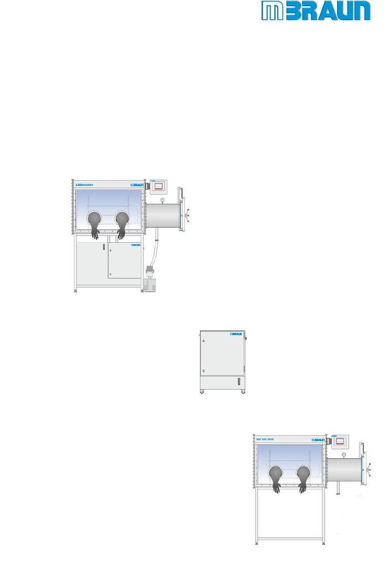
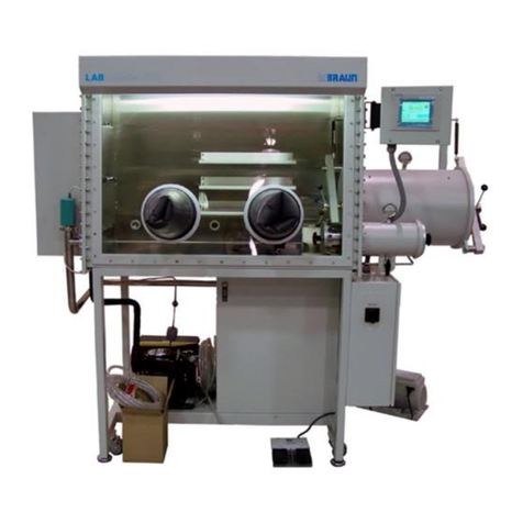
MBRAUN MB-20G User manual

OPERATING INSTRUCTIONS
1
2
3
4
5
6
7
8
9
10
11
12
13
14
15
16
General Information
Transport / Side Selection
Preparing the Connections
Installation
Activating the System
OP 17 Operation Panel
Purging the System
Pressure Control System
Circulation Mode
Regeneration
Settings and Display Types
Antechamber Operation
Dust Filters
Analyzers
Maintenance and Service
Spare Parts List
Operating
Instructions
for MBRAUN systems
with one purier column
• MB 20G
• MB 30G
• Workstation MB 120B-G
• Workstation MB 150B-G-I
• Workstation Labmaster
• Glove-Boxes

Copyright: © 2001 by MBRAUN GmbH
Gutenbergstr. 7 • D-85748 Garching
Telefon (0 89) 32 00 96-0 • Telefax (0 89) 32 00 96-25
E-Mail: [email protected] • www.mbraun.de • www.mbraun.com
Printed in Germany 2001
Title: Operating instructions for MBRAUN systems with one
purier column
Edition: 07.2001
Technical consultation: A. Ripp, Dept. Technical Documentation M. Braun GmbH
Technical assistents: M. Seidinger M. Braun GmbH
B. Wurmseher M. Braun GmbH
T. Kramer M. Braun GmbH
Layout: K. Oertel, Dept. Graphic M. Braun GmbH
Publication edited by means of: Adobe InDesign©, Corel Draw©, Adobe Photoshop©
Important notes: This technical documentation is not liable to any obligations on
the part of the manufacturer. The manufacturer M.Braun GmbH
reserves the right for technical and optical modications as well
as functional modications on the systems or system’s compo-
nents described therein.
Any duplication of this documentation, even in form of excerpts,
is only permitted after having obtained the manufacturer’s
information and concession.

General Information Chapter 1
General information . . . . . . . . . . . . . . . . . . . . . . . . . . . . . . . . . . . 9
Entries referring to the system . . . . . . . . . . . . . . . . . . . . . . . . . 9
Addresses . . . . . . . . . . . . . . . . . . . . . . . . . . . . . . . . . . . . . . . . 10
Transport / Site Selection Chapter 2
Transport of a system . . . . . . . . . . . . . . . . . . . . . . . . . . . . . . . . 13
Site selection for a system . . . . . . . . . . . . . . . . . . . . . . . . . . . 13
Modication of a system . . . . . . . . . . . . . . . . . . . . . . . . . . . . 13
Preparing the Connections Chapter 3
General information . . . . . . . . . . . . . . . . . . . . . . . . . . . . . . . . . . 17
Operating gases . . . . . . . . . . . . . . . . . . . . . . . . . . . . . . . . . . . . 17
Equipment for connections . . . . . . . . . . . . . . . . . . . . . . . . . . . 17
Installation Chapter 4
Safety instructions . . . . . . . . . . . . . . . . . . . . . . . . . . . . . . . . . . . 23
Getting the system connected . . . . . . . . . . . . . . . . . . . . . . . . 23
Activating the System Chapter 5
Prerequisites . . . . . . . . . . . . . . . . . . . . . . . . . . . . . . . . . . . . . . 27
Activating the system . . . . . . . . . . . . . . . . . . . . . . . . . . . . . . . 27
Start messages . . . . . . . . . . . . . . . . . . . . . . . . . . . . . . . . . . . . 27
Activating the vacuum pump . . . . . . . . . . . . . . . . . . . . . . . . . 28
Deactivating the system . . . . . . . . . . . . . . . . . . . . . . . . . . . . . 28
OP 17 Operation Panel Chapter 6
Overview . . . . . . . . . . . . . . . . . . . . . . . . . . . . . . . . . . . . . . . . . 31
Display . . . . . . . . . . . . . . . . . . . . . . . . . . . . . . . . . . . . . . . . . . 31
Softkeys . . . . . . . . . . . . . . . . . . . . . . . . . . . . . . . . . . . . . . . . . 31
Hardkeys . . . . . . . . . . . . . . . . . . . . . . . . . . . . . . . . . . . . . . . . 31
Controlkeys . . . . . . . . . . . . . . . . . . . . . . . . . . . . . . . . . . . . . . 32
Purging the System Chapter 7
General information . . . . . . . . . . . . . . . . . . . . . . . . . . . . . . . . . 35
When is purging necessary . . . . . . . . . . . . . . . . . . . . . . . . . . . 35
“MBRAUN QuickPurge” automatic purging system . . . . . . . . . 36
Pressure Control System Chapter 8
General information . . . . . . . . . . . . . . . . . . . . . . . . . . . . . . . . 39
Principle . . . . . . . . . . . . . . . . . . . . . . . . . . . . . . . . . . . . . . . . . 39
Explanation of the terms . . . . . . . . . . . . . . . . . . . . . . . . . . . . . 39
Changing the box pressure within the working area . . . . . . . . 40
Table of Contents
TABLE OF CONTENTS I

Circulation Mode Chapter 9
General information . . . . . . . . . . . . . . . . . . . . . . . . . . . . . . . . . 43
Prerequisites . . . . . . . . . . . . . . . . . . . . . . . . . . . . . . . . . . . . . . 43
Circulation mode (systems with 1 purier column) . . . . . . . . . 44
Regeneration Chapter 10
General information . . . . . . . . . . . . . . . . . . . . . . . . . . . . . . . . . 49
Prerequisites . . . . . . . . . . . . . . . . . . . . . . . . . . . . . . . . . . . . . . 49
Settings and Display Patterns Chapter 11
General information . . . . . . . . . . . . . . . . . . . . . . . . . . . . . . . . . . 55
Message level . . . . . . . . . . . . . . . . . . . . . . . . . . . . . . . . . . . . . . 55
Selection levels . . . . . . . . . . . . . . . . . . . . . . . . . . . . . . . . . . . . . 55
Operating hours . . . . . . . . . . . . . . . . . . . . . . . . . . . . . . . . . . . . 56
Status . . . . . . . . . . . . . . . . . . . . . . . . . . . . . . . . . . . . . . . . . . . . 56
Parameter indicate . . . . . . . . . . . . . . . . . . . . . . . . . . . . . . . . . . 57
Information . . . . . . . . . . . . . . . . . . . . . . . . . . . . . . . . . . . . . . . . 57
Set mode . . . . . . . . . . . . . . . . . . . . . . . . . . . . . . . . . . . . . . . . . . 57
Parameter set . . . . . . . . . . . . . . . . . . . . . . . . . . . . . . . . . . . . . .58
Setting areas in the selection level 2 . . . . . . . . . . . . . . . . . . . . . 58
Antechamber Operation Chapter 12
General information . . . . . . . . . . . . . . . . . . . . . . . . . . . . . . . . . 63
Principle . . . . . . . . . . . . . . . . . . . . . . . . . . . . . . . . . . . . . . . . . 63
Overview . . . . . . . . . . . . . . . . . . . . . . . . . . . . . . . . . . . . . . . . . 63
Important notes . . . . . . . . . . . . . . . . . . . . . . . . . . . . . . . . . . . 64
Transferring material into the box (standard operation) . . . . . 64
Transferring material into antechamber (automatic control) . . .66
Information about the antechamber automatic control . . . . . . 67
Transferring material out of the box . . . . . . . . . . . . . . . . . . . . . 68
Circular antechamber . . . . . . . . . . . . . . . . . . . . . . . . . . . . . . . 69
Mini antechambers . . . . . . . . . . . . . . . . . . . . . . . . . . . . . . . . . 71
Dust Filters Chapter 14
General Information . . . . . . . . . . . . . . . . . . . . . . . . . . . . . . . . 77
Exchange Dust Filters . . . . . . . . . . . . . . . . . . . . . . . . . . . . . . . 77
Analyzers Chapter 15
General Information . . . . . . . . . . . . . . . . . . . . . . . . . . . . . . . . 81
Oxygen Analyzer MB-OX-SE-1 . . . . . . . . . . . . . . . . . . . . . . . . 83
Moisture Analyzer MB-MO-SE-1 . . . . . . . . . . . . . . . . . . . . . . . 85
Maintenance and Service Chapter 16
Components of third-party manufacturers . . . . . . . . . . . . . . . . 93
Daily maintenance and service . . . . . . . . . . . . . . . . . . . . . . . . 93
Quarterly and annual maintenance and service . . . . . . . . . . 94
II TABLE OF CONTENTS

Spare Parts List Chapter 16
Gas purication system MB 20G . . . . . . . . . . . . . . . . . . . . . . 97
Workstation Labmaster 130 . . . . . . . . . . . . . . . . . . . . . . . . . . 98
Gas purication system Labmaster 130 . . . . . . . . . . . . . . . . . . 99
Mini antechamber Labmaster 130 . . . . . . . . . . . . . . . . . . . . . 100
Antechamber Labmaster 130 . . . . . . . . . . . . . . . . . . . . . . . . . 101
Control Labmaster 130 . . . . . . . . . . . . . . . . . . . . . . . . . . . . . .102
Gas Purication System MB 30G . . . . . . . . . . . . . . . . . . . . . .103
Workstation MB 120B-G . . . . . . . . . . . . . . . . . . . . . . . . . . . . 103
Workstation MB 150B-G-I . . . . . . . . . . . . . . . . . . . . . . . . . . . 103
Index . . . . . . . . . . . . . . . . . . . . . . . . . . . . . . . . . . . . . . . . . . .105
TABLE OF CONTENTS III

OPERATING INSTRUCTIONS
Chapter 1
General Information
MBRAUN 1

OPERATING INSTRUCTIONS
Index of Chapter 1
General Information
General Information . . . . . . . . . . . . . . . . . . . . . . . 9
Entries referring to the system . . . . . . . . . . . . . . . 9
Addresses . . . . . . . . . . . . . . . . . . . . . . . . . . . . . 10

This documentation is part of the system:
Space left for notes on system settings, instructions for maintenance etc.
Chapter 1
General Information
9
Chapter 1: General Information
Designation / Type:
Series number (s):
Persons in charge of the system:
Entries referring to the system

Important service addresses:
M. Braun Inc.
14 Marin Way
Stratham, NH 03885
Phone: 603-773-9333
Fax (service dept.): 603-773-0008
E-Mail: service@mbraun.com
Internet: www.mbraun.com
Chapter 1
General Information
10
Addresses

OPERATING INSTRUCTIONS
Chapter 2
Transport / Site Selection /
Modication
MBRAUN 2

OPERATING INSTRUCTIONS
Index of Chapter 2
Transport / Site Selection /
Modication Transport of a system . . . . . . . . . . . . . . . . . . . . . . 13
Site selection for a system . . . . . . . . . . . . . . . . . . 13
Modication of a system . . . . . . . . . . . . . . . . . . . . 13

Chapter 2
Transport / Site Selection / Modication
13
Chapter 2: Transport/Site Selection/Modication
The preparations for transporting an MBRAUN System should be carried out by an MBRAUN technician only.
The transport of the system should be done by a forwarding agency specializing in this procedure.
If the system is part of another system line, the instructions of this system line are also valid.
Selecting the site for an MBRAUN System of the series should be carried out by MBRAUN technicians only.
If the system is part of another system line, the instructions of this system line are also valid.
Prerequisites:
In principle, changes and modications of any kind on MBRAUN Glove-Systems of the series should be made
by MBRAUN technicians only.
For exceptions of any kind, a written conrmation is required.
In case of contravention all claims under warranty and those to liability will expire.
If the system is part of another system line, the instructions of this system line are also valid.
Room temperature +15°C to +30°C, dry and well ventilated
Firmly structured oor, no oblique position!
Optimum clearance from the walls of the room, min. 600 mm
Room:
Surface conditions:
Clearance:
Transport of a system
Site selection for a system
Modication of a system


OPERATING INSTRUCTIONS
Chapter 3
Preparing the Connections
MBRAUN 3

OPERATING INSTRUCTIONS
Index of Chapter 3
Preparing the Connections
General information . . . . . . . . . . . . . . . . . . . . . . . .17
Operating gases . . . . . . . . . . . . . . . . . . . . . . . . . . .17
Equipment for connections . . . . . . . . . . . . . . . . . . .17

Chapter 3: Preparing the Connections
The accessories described in this chapter are required for connecting the system. They are not included in
the system’s delivery package.
Working gas
Regeneration gas
Purge gas
Prior to delivery of the system the user will receive an information sheet with exact specications about the
necessary accessories for connections required for the system ordered. The following specications are only
a general overview.
Building up and maintaining the ultra pure gas atmosphere and pressure gas for
electropneumatic valves
Nitrogen, argon or helium
Medium purity; from bottles or other gas supply facilities
Use:
Gas type:
Purity:
Permanent supply for the system’s operation (e.g. for pressure compensation)Quantity:
Reprocessing saturated H2O/O2 purier columnsUse:
Depending on the type of application:
Nitrogen/hydrogen mixture (90 to 95% N2 with 5 to 10% H2 portion) when nitrogen
is used as working gas or
Argon/hydrogen mixture (90 to 95% Ar with 5 to 10% H2 portion) when argon is used
as working gas or
Helium/hydrogen mixture (90 to 95% He with 5 to 10% H2 portion) when helium is
used as working gas
Medium purity; from bottles or other gas supply facilities
Gas type:
Purity:
Approx. 3,500 liter for each regeneration procedureQuantity:
Getting the system lled up and purged with working gas (when commissioning for
the rst time and after servicing or repairs of the system)
Working gas (nitrogen, argon or helium)
Medium purity; from bottles or other gas supply facilities
Use:
Gas type:
Purity:
Approx. 8,000 to 10,000 liters for each m3 box volume for purging the system when
commissioning the system for the rst time or intermediately purging the system
Quantity:
General information
Operating gases
Equipment for connections
Chapter 3
Preparing the Connections
17

Equipment for working gas connections
Pressure reducing valve for working gas
Supply piping for working gas
Equipment for regeneration gas connections
Pressure reducing valve for regeneration gas
Supply piping for regeneration gas
Working gas pressure control system
200 bar primary, 5.5 to 6 bar secondary
9 mm dia. hose nozzle or 10 mm dia. Swagelok© screwed tting
Use:
Material:
Connection type:
Connecting the working gas source with the “Working Gas INLET” system connection
Optional (length as required):
either:
9 mm dia. reinforced hose, 3 mm wall thickness and adapter, 9 mm dia. hose
nozzle with 10 mm dia. Swagelok© screwed tting
or:
10 mm dia. copper pipe and 10 mm dia. Swagelok© screwed tting
or:
10 mm dia. stainless steel pipe and 10 mm dia. Swagelok© screwed tting
9 mm dia. hose nozzle or 10 mm dia. Swagelok© screwed tting
Use:
Material:
Connection type:
Regeneration gas pressure control system
Connecting the regeneration gas source with the “Regeneration gas INLET” system connection
Optional (length as required):
either:
9 mm dia. reinforced hose, 3 mm wall thickness and adapter, 9 mm dia. hose
nozzle with 10 mm dia. Swagelok© screwed tting
or:
10 mm dia. copper pipe and 10 mm dia. Swagelok© screwed tting
or:
10 mm dia. stainless steel pipe and 10 mm dia. Swagelok© screwed tting
9 mm dia. hose nozzle or 10 mm dia. Swagelok© screwed tting
Use:
Material:
Connection type:
200 bar primary, 0.3 - 0.4 bar secondary
9 mm dia. hose nozzle or 10 mm dia. Swagelok© screwed tting
Use:
Material:
Connection type:
Chapter 3
Preparing the Connections
18

Exhaust outlet for waste regeneration gas
Connecting equipment for purge gas
Pressure reducing valve for purge gas
Required only for the “manual purging” method.
When using the optional “MBRAUN QuickPurge” purging method no preparations are required, in this case the
working gas connection is used.
Supply piping for purge gas
Required only for the “manual purging” method.
When using the optional “MBRAUN QuickPurge” purging method no preparations are required, in this case the
working gas connection is used.
Optional (length as required):
either:
9 mm dia. reinforced hose, 3 mm wall thickness and adapter, 9 mm dia. hose
nozzle with 10 mm dia. Swagelok© screwed tting
or:
10 mm dia. copper pipe and 10 mm dia. Swagelok© screwed tting
or:
10 mm dia. stainless steel pipe and 10 mm dia. Swagelok© screwed tting
9 mm dia. hose nozzle or 10 mm dia. Swagelok© screwed tting
Material:
Connection type:
Connecting the “Regeneration gas OUTLET” system connection with the factory’s
disposal facility (exhaust outlet)
Use:
Connecting the purge gas source with the purge hose
9 mm dia. reinforced hose, 3 mm wall thickness, length as required
Use:
Material:
Pressure control of the purge gas when manual purging is applied
Primary 200 bar, secondary 5 to 6 bar
9 mm dia. hose nozzle or 10 mm dia. Swagelok© screwed tting
Use:
Material:
Connection type:
Chapter 3
Preparing the Connections
19

Connecting equipment for vacuum pumps
Exhaust piping for vacuum pump waste gas
Connecting equipment for the water cooling
Cooling water
Supply pipings for water cooling (supply and drain piping)
Power connection
Depending on the system, refer to type plate.
Optional (length as required):
either:
9 mm dia. reinforced hose, 3 mm wall thickness and adapter, 9 mm dia. hose
nozzle with 10 mm dia. Swagelok© screwed tting
or:
10 mm dia. copper pipe and 10 mm dia. Swagelok© screwed tting
or:
10 mm dia. stainless steel pipe and 10 mm dia. Swagelok© screwed tting
Material:
Optional (length as required):
either:
16 mm dia. reinforced hose and 16 mm hose nozzle
or:
16 mm dia. copper pipe, as well as ange and clamp
or:
16 mm dia. stainless steel pipe as well as ange and clamp
Cooling the system
Tap water
water temperature: 10°C to 15°C
ow rate: 2 l/min at 10°C, 5 l/min at 15°C
water disposal: depressurized
Use:
Material:
Material:
Connecting the vacuum pump exhaust (oil mist and waste gas) with the factory’s
waste gas disposal facility (depressurized exhaust outlet)
Use:
Chapter 3
Preparing the Connections
20

OPERATING INSTRUCTIONS
Chapter 4
Installation
MBRAUN 4
This manual suits for next models
3
Table of contents
Other MBRAUN Laboratory Equipment manuals