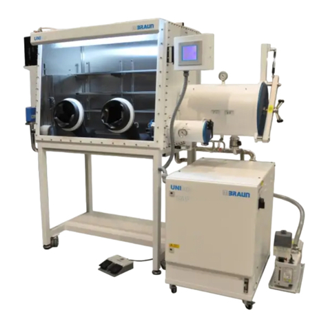
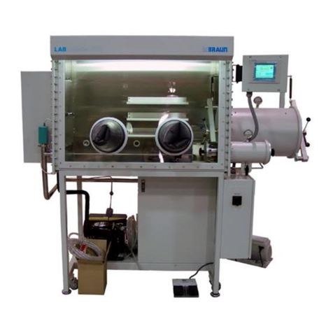
MBRAUN LABmaster pro sp User manual

Inertgas-Systems
§Workstation LABmaster pro sp / dp
§Gas purifier MB-20-G / MB-200G-W
§MOD box MB200MOD
with touch panel TP700
Operating Manual
Document number: 2611275-EN V5.0 • 12/04/2018
Sales number: 1501101 ... 1501132 (LABmaster), 1500111 (MB-20-G), 1500114 (MB-200G-W), 1500050 ...1500092
(MOD Box)

MB-20-G/MB-200G-W_MB-LABmaster_MB-200 MOD_TP700
Operating Manual - V5.0 - 04/2018 - STD
Legal information
Operating Manual
§Workstation LABmaster pro sp / dp
§Gas purifier MB-20-G / MB-200G-W
§MOD box MB200MOD
with touch panel TP700
M. Braun Inertgas-Systeme GmbH
Dieselstr. 31
85748 Garching
Germany
Website: www.mbraun.de
Phone: +49 (0)89 32669-0
Fax. +49 (0)89 32669-235
Email [email protected]

Table of Contents
Document number: 2611275-EN Sales number: 1501101 ... 1501132 (LABmaster), 1500111 (MB-20-G), 1500114
(MB-200G-W), 1500050 ...1500092 (MOD Box)
MB-20-G/MB-200G-W_MB-LABmaster_MB-200 MOD_TP700
Operating Manual - V5.0 - 04/2018 - STD
Page
1
Table of Contents
1 General information ...................................................................... 1- 1
1.1 Entries referring to the system .................................................... 1- 1
1.2 Scope of delivery .......................................................................... 1- 1
1.3 Type plate ...................................................................................... 1- 2
1.4 Liability........................................................................................... 1- 3
1.5 Warranty......................................................................................... 1- 4
1.6 Modifications ................................................................................. 1- 4
1.7 Service address............................................................................. 1- 4
1.8 Included description of optional features................................... 1- 5
1.9 About this operating manual ....................................................... 1- 6
1.9.1 General............................................................................1- 6
1.9.2 Availability of instructions ................................................1- 6
1.9.3 Safety warnings in this manual........................................1- 6
1.9.4 Conventions used in this manual ....................................1- 7
1.9.5 Units used........................................................................1- 8
1.9.6 Terms used......................................................................1- 8
1.9.7 Abbreviations...................................................................1- 9
1.9.8 Glossary ........................................................................1- 10
1.9.9 Disclaimer......................................................................1- 11
2 Inert gas technology ..................................................................... 2- 1
2.1 Overview ........................................................................................ 2- 1
2.2 Components .................................................................................. 2- 2
2.2.1 Glovebox .........................................................................2- 2
2.2.2 Antechamber ...................................................................2- 6
2.2.3 Gas purifier......................................................................2- 9
2.2.4 System control...............................................................2- 11
2.2.5 Vacuum pump ...............................................................2- 13
2.3 Functional description................................................................ 2- 14
2.3.1 Gas flow general............................................................2- 14
2.3.2 Single reactor systems (sp)...........................................2- 16
2.3.3 Optional: double purifier (dp).........................................2- 17
2.3.4 Optional: solvent filter....................................................2- 17
2.3.5 Box pressure control......................................................2- 19
2.3.6 Vacuum antechamber ...................................................2- 22
2.4 MBRAUN standard platforms..................................................... 2- 25
2.4.1 MB-20-G and MB-200G-W............................................2- 25
2.4.2 LABmaster pro workstation ...........................................2- 25
2.4.3 MOD box systems .........................................................2- 26
2.4.4 Technical data ...............................................................2- 26
2.4.5 Noise level.....................................................................2- 28
2.4.6 On-site conditions..........................................................2- 28
3 Safety ............................................................................................. 3- 1
3.1 Intended use .................................................................................. 3- 1
3.2 Improper use ................................................................................. 3- 2
3.3 Statement of the manufacturer .................................................... 3- 3

Table of Contents
Page
2
MB-20-G/MB-200G-W_MB-LABmaster_MB-200 MOD_TP700
Operating Manual - V5.0 - 04/2018 - STD
3.4 Qualification of personnel............................................................ 3- 4
3.5 Duties of the operating personnel............................................... 3- 4
3.6 Duties of the operating company ................................................ 3- 5
3.7 Behaviour in case of emergency ................................................. 3- 6
3.8 Process materials ......................................................................... 3- 6
3.8.1 Classification and assessment of substances.................3- 6
3.8.2 MBRAUN-Hazard classes ...............................................3- 7
3.8.3 Examples of a rough classification ..................................3- 9
3.9 Safe handling of solvents, chemicals and gases..................... 3- 11
3.10 Controller ..................................................................................... 3- 12
3.11 Gas purifier regeneration ........................................................... 3- 12
3.12 Regenerative solvent filter ......................................................... 3- 12
3.13 Residual risks.............................................................................. 3- 12
3.13.1 Risk of overpressure and negative pressure.................3- 12
3.13.2 Risk of electrical hazard ................................................3- 13
3.13.3 Risk of suffocation .........................................................3- 14
3.13.4 Risk of combustion and explosion.................................3- 14
3.13.5 Risks when operating a damaged system.....................3- 14
3.13.6 Risk of environmental damage......................................3- 14
3.14 Safety symbols affixed to the inert gas system ....................... 3- 15
4 Transport, installation and commissioning................................ 4- 1
4.1 Transport ....................................................................................... 4- 1
4.1.1 Important transport labels................................................4- 1
4.1.2 Storage conditions...........................................................4- 2
4.1.3 Long-haul carriage ..........................................................4- 2
4.1.4 On-site transport and unpacking .....................................4- 2
4.1.5 Moving a glovebox...........................................................4- 4
4.1.6 Moving a gas purifier .......................................................4- 6
4.1.7 Moving a LABmaster .......................................................4- 8
4.1.8 Rolling the equipment into position ...............................4- 10
4.2 Installation ................................................................................... 4- 10
4.2.1 Definition of the clean room volume ..............................4- 11
4.2.2 Preparing the site ..........................................................4- 12
4.2.3 Media supply overview .................................................4- 14
4.2.4 System cooling ..............................................................4- 20
4.2.5 Installation vacuum pump..............................................4- 21
4.2.6 Connecting the system..................................................4- 21
4.2.7 Installation of the analysers...........................................4- 29
4.2.8 Final inspection..............................................................4- 30
4.3 Commissioning ........................................................................... 4- 30
4.3.1 Switching on the system................................................4- 30
4.3.2 Inertisation of the glovebox ...........................................4- 31
5 Human machine interface ............................................................ 5- 1
5.1 Introduction ................................................................................... 5- 1
5.2 Touch panel ................................................................................... 5- 1
5.3 Explanation of symbols and colours .......................................... 5- 2
5.4 Start screen ................................................................................... 5- 4

Table of Contents
MB-20-G/MB-200G-W_MB-LABmaster_MB-200 MOD_TP700
Operating Manual - V5.0 - 04/2018 - STD
Page
3
5.5 Screen components...................................................................... 5- 6
5.6 Functions screens ........................................................................ 5- 6
5.7 Alarm screen ................................................................................. 5- 7
5.8 Menu Screen selection screen..................................................... 5- 8
5.8.1 Parameter screens ..........................................................5- 8
5.8.2 Trend screens..................................................................5- 9
5.8.3 Service screen...............................................................5- 10
5.9 User level / password concept................................................... 5- 13
5.9.1 Logon.............................................................................5- 13
5.9.2 Logout............................................................................5- 14
5.10 Default parameter values ........................................................... 5- 14
6 Operating mode principles........................................................... 6- 1
6.1 Service book.................................................................................. 6- 1
6.2 Starting up the system ................................................................. 6- 1
6.3 Gas purifier operating modes ...................................................... 6- 3
6.4 Glovebox operating modes.......................................................... 6- 4
6.5 Antechamber operating modes ................................................... 6- 4
6.6 Shut down system ........................................................................ 6- 4
7 Gas purifier operation................................................................... 7- 1
7.1 Safe operation ............................................................................... 7- 1
7.1.1 Parameter limits...............................................................7- 1
7.1.2 Select regeneration gas hydrogen concentration............7- 1
7.1.3 Solvent and solvent filters ...............................................7- 1
7.2 Navigation overview ..................................................................... 7- 2
7.2.1 Purification unit................................................................7- 2
7.2.2 Analysers.........................................................................7- 5
7.2.3 Regenerative solvent filter (optional)...............................7- 6
7.3 Circulation ..................................................................................... 7- 8
7.3.1 Manual activation and deactivation .................................7- 8
7.3.2 Automatic circulation activation .....................................7- 12
7.4 Solvent filter operation (optional).............................................. 7- 13
7.4.1 Manually operated solvent filters (activated carbon only)
.......................................................................................7- 13
7.4.2 PLC-controlled solvent filters.........................................7- 14
7.4.3 Solvent analyser (optional)............................................7- 16
7.5 Regeneration operation.............................................................. 7- 16
7.5.1 Regeneration sequence ................................................7- 17
7.5.2 Reactor regeneration.....................................................7- 18
7.5.3 Solvent filter regeneration .............................................7- 21
7A ECO Mode ....................................................................................7A- 1
7A.1 Overview ......................................................................................7A- 1
7A.2 Glovebox operation with the ECO Mode feature......................7A- 1
7A.2.1 Regeneration................................................................ 7A- 2
7A.2.2 Dedicated vacuum pumps for antechamber................. 7A- 2
7A.3 Safety ...........................................................................................7A- 3

Table of Contents
Page
4
MB-20-G/MB-200G-W_MB-LABmaster_MB-200 MOD_TP700
Operating Manual - V5.0 - 04/2018 - STD
7A.4 Operation .....................................................................................7A- 3
7A.4.1 Navigation..................................................................... 7A- 3
7A.4.2 Parameters................................................................... 7A- 4
7A.4.3 Reduced Blower speed ................................................ 7A- 5
7A.4.4 The different blower speeds ......................................... 7A- 6
7A.4.5 Vacuum pumps............................................................. 7A- 7
7A.4.6 Antechamber with dedicated vacuum pump ................ 7A- 7
7A.4.7 Box light........................................................................ 7A- 8
8 Glovebox or enclosure operation................................................ 8- 1
8.1 Overview ........................................................................................ 8- 1
8.2 Safe operation ............................................................................... 8- 1
8.2.1 Overpressure safety ........................................................8- 2
8.2.2 Harmful or hazardous process materials.........................8- 2
8.2.3 Process-related particle formation...................................8- 2
8.2.4 Mechanical hazards.........................................................8- 3
8.2.5 Reactor damage by ambient air ......................................8- 3
8.3 Inertisation..................................................................................... 8- 3
8.4 Working with gloves and glovebreaks........................................ 8- 4
8.5 Monitoring gas concentration...................................................... 8- 5
8.5.1 Display H2O and O2 concentration.................................8- 5
8.5.2 Glovebox trend screen ....................................................8- 6
8.5.3 Activation and deactivation of analysers .........................8- 7
8.5.4 Analyser operating hours ................................................8- 8
8.6 Setting glovebox parameters....................................................... 8- 8
8.7 Activation / Deactivation of glovebox functions ...................... 8- 10
8.8 Glovebox during circulation ...................................................... 8- 10
8.8.1 Glovebox pressure ........................................................8- 11
8.8.2 Rough leakage detection...............................................8- 12
8.8.3 Solvent vapours in glovebox atmosphere .....................8- 12
8.9 Glovebox during regeneration................................................... 8- 13
8.10 Glovebox purge........................................................................... 8- 13
8.10.1 Manually start and stop .................................................8- 15
8.10.2 Automatic start and stop................................................8- 15
8.11 Additional function and equipment from MBRAUN................. 8- 17
8.11.1 Additional equipment.....................................................8- 17
8.11.2 Additional safety equipment ..........................................8- 18
8.12 Operating company’s process equipment ............................... 8- 18
8A O2 and H2O analysers ................................................................8A- 1
8A.1 Overview of a O2 and a H2O analyser.......................................8A- 1
8A.2 Safety ...........................................................................................8A- 2
8A.2.1 Intended use................................................................. 8A- 2
8A.2.2 Improper use MB-OX-SE1............................................ 8A- 2
8A.2.3 Improper use of the moisture analyser......................... 8A- 2
8A.3 Oxygen analyser .........................................................................8A- 2
8A.3.1 Description.................................................................... 8A- 2
8A.3.2 Technical data .............................................................. 8A- 3
8A.3.3 Installing the oxygen analyser ...................................... 8A- 3
8A.3.4 Maintenance................................................................. 8A- 4

Table of Contents
MB-20-G/MB-200G-W_MB-LABmaster_MB-200 MOD_TP700
Operating Manual - V5.0 - 04/2018 - STD
Page
5
8A.4 Moisture analyser........................................................................8A- 4
8A.4.1 Description.................................................................... 8A- 4
8A.4.2 Technical data .............................................................. 8A- 5
8A.4.3 Installing the moisture analyser.................................... 8A- 5
8A.4.4 Maintenance for the H2O analyser............................... 8A- 6
8A.4.5 Storing an MB-MO-SE1 analyser ............................... 8A- 10
8A.5 Mounting an analyser ...............................................................8A- 10
8A.6 Disassembling or replacing the analyser ...............................8A- 11
8A.7 Returning analysers to MBRAUN ............................................8A- 12
8A.7.1 Return service ............................................................ 8A- 12
8A.7.2 Returning a faulty analyser......................................... 8A- 12
8A.7.3 Returning an analyser for calibration.......................... 8A- 14
8A.8 Declaration about Decontamination.pdf .................................8A- 15
8B Freezer .........................................................................................8B- 1
8B.1 Overview ......................................................................................8B- 1
8B.2 Specifications..............................................................................8B- 2
8B.3 Operation .....................................................................................8B- 2
9 Antechamber operation (Vacuum antechamber) ....................... 9- 1
9.1 Safe operation ............................................................................... 9- 1
9.2 Vacuum pump ............................................................................... 9- 2
9.3 Antechamber door operation....................................................... 9- 2
9.3.1 Main antechamber...........................................................9- 3
9.3.2 Mini antechamber............................................................9- 4
9.4 Manual loading and unloading of the mini antechamber.......... 9- 6
9.4.1 Transferring material in....................................................9- 6
9.4.2 Transferring material out .................................................9- 8
9.5 PLC-controlled loading and unloading ....................................... 9- 9
9.5.1 Touch panel navigation .................................................9- 10
9.5.2 Parameters....................................................................9- 12
9.5.3 Trend curve ...................................................................9- 14
9.5.4 Antechamber cycle operation........................................9- 14
9.5.5 Loading and unloading ..................................................9- 17
9.6 PLC-controlled door interlock ................................................... 9- 17
9.7 Optional antechamber features ................................................. 9- 20
10 Additional equipment ................................................................. 10- 1
10.1 Introduction ................................................................................. 10- 1
10.2 Safety ........................................................................................... 10- 1
10.3 Additional options....................................................................... 10- 1
10.3.1 Optional glovebox equipment........................................10- 2
10.3.2 Optional antechamber equipment .................................10- 4
10.4 Customer-specific components ................................................ 10- 4
10.5 Equipment from other manufactures ........................................ 10- 4
10A myMBRAUN App .......................................................................10A- 1
10A.1 Setting up the myMBRAUN app...............................................10A- 1
10A.1.1 Prerequisites............................................................... 10A- 1

Table of Contents
Page
6
MB-20-G/MB-200G-W_MB-LABmaster_MB-200 MOD_TP700
Operating Manual - V5.0 - 04/2018 - STD
10A.1.2 Preparatory steps ....................................................... 10A- 1
10A.1.3 Main menu of the app................................................. 10A- 1
10A.1.4 Registering ................................................................. 10A- 2
10A.2 Functions ...................................................................................10A- 7
10A.2.1 Settings....................................................................... 10A- 7
10A.2.2 Monitoring................................................................... 10A- 8
10A.2.3 Information................................................................ 10A- 11
10A.3 Legal notice .............................................................................10A- 11
10A.4 Account information ...............................................................10A- 11
10A.5 Attachement ............................................................................10A- 11
10A.5.1 White Paper_Data Protection.pdf............................. 10A- 13
11 Troubleshooting.......................................................................... 11- 1
11.1 Eliminating faults ........................................................................ 11- 1
11.1.1 PLC................................................................................11- 1
11.1.2 Gas purifier....................................................................11- 1
11.1.3 Glovebox .......................................................................11- 1
11.1.4 Antechamber .................................................................11- 3
11.2 Stack light (optional)................................................................... 11- 4
11.3 ACK Warning and alarm messages........................................... 11- 4
11.3.1 Acknowledgement of a message ..................................11- 4
11.3.2 Deletion of a warning message .....................................11- 5
11.4 Definition of alarm and warning messages .............................. 11- 5
11.5 Failure during regeneration ..................................................... 11- 18
11.5.1 Cancellation or power failure.......................................11- 18
11.5.2 Regeneration of an LMF..............................................11- 18
11.6 Leak test..................................................................................... 11- 18
12 Maintenance ................................................................................ 12- 1
12.1 Introduction ................................................................................. 12- 1
12.1.1 Document inspection and maintenance ........................12- 1
12.1.2 Spare parts kit ...............................................................12- 2
12.1.3 Who may do what?........................................................12- 2
12.1.4 Qualification of maintenance personnel ........................12- 2
12.2 Maintenance plan overview........................................................ 12- 3
12.2.1 System in general..........................................................12- 3
12.2.2 Non-regenerative LMF...................................................12- 3
12.2.3 Regenerative LMF.........................................................12- 4
12.2.4 Gloves ...........................................................................12- 4
12.2.5 Mini Antechamber..........................................................12- 4
12.2.6 Main Antechamber ........................................................12- 5
12.2.7 Vacuum pump ...............................................................12- 6
12.2.8 Gas purifier....................................................................12- 6
12.2.9 Glovebox .......................................................................12- 7
12.3 Maintenance contract with MBRAUN ........................................ 12- 8
12.3.1 Analyser calibration .......................................................12- 8
12.3.2 Safety E-check service..................................................12- 8
12.4 Safety during maintenance work............................................... 12- 8
12.5 Preparations for inspection and maintenance work................ 12- 9
12.5.1 Shut down and de-energization.....................................12- 9

Table of Contents
MB-20-G/MB-200G-W_MB-LABmaster_MB-200 MOD_TP700
Operating Manual - V5.0 - 04/2018 - STD
Page
7
12.5.2 General advice for maintenance work.........................12- 10
12.6 Maintenance works ................................................................... 12- 11
12.6.1 Glovebox .....................................................................12- 11
12.6.2 Gloves .........................................................................12- 12
12.6.3 Particle filter.................................................................12- 16
12.6.4 Calibrating and cleaning analysers .............................12- 17
12.6.5 Antechamber ...............................................................12- 17
12.6.6 Reactor........................................................................12- 17
12.6.7 Vacuum pump .............................................................12- 18
12.6.8 Non-regenerative LMF (optional) ................................12- 18
12.6.9 Optional and 3rd party components ............................12- 20
12.7 Completing maintenance ......................................................... 12- 20
12.8 Returning components for service purposes ........................ 12- 21
12.9 Decommissioning ..................................................................... 12- 21
12.10 Annex ......................................................................................... 12- 22
12.10.1 Declaration about Decontamination.pdf ......................12- 23
13 Spare parts .................................................................................. 13- 1
13.1 Introduction ................................................................................. 13- 1
13.2 Gas purifier .................................................................................. 13- 1
13.2.1 Front view......................................................................13- 1
13.2.2 Rear view.......................................................................13- 2
13.2.3 Box purge function (optional) ........................................13- 4
13.2.4 ECO Mode.....................................................................13- 4
13.2.5 Solvent filter (optional)...................................................13- 5
13.3 Glovebox...................................................................................... 13- 7
13.3.1 Chassis and lighting ......................................................13- 7
13.3.2 Gloves and glove parts..................................................13- 7
13.4 Particle filter .............................................................................. 13- 10
13.5 Analyser ..................................................................................... 13- 10
13.6 Antechamber ............................................................................. 13- 11
13.6.1 Main antechamber,
∅
390...........................................13- 11
13.6.2 Mini antechamber Ø 150 mm ......................................13- 12
13.7 Vacuum pump ........................................................................... 13- 12
13.7.1 Oil sealed vacuum pump.............................................13- 12
13.7.2 Dry vacuum pump .......................................................13- 13
13.8 Touch panel TP700 ................................................................... 13- 13
13.9 Foot switch ................................................................................ 13- 14
14 3rd party documentation ............................................................ 14- 1
14.1 List of attached 3rd party documentation ................................ 14- 1
15 Certificates................................................................................... 15- 1
15.1 Declarations................................................................................. 15- 1
16 Electrical and wiring diagram(s)................................................ 16- 1
16.1 Safety ........................................................................................... 16- 1
16.1.1 Basic rules for working with electrical systems..............16- 1
16.1.2 Electrical safety check...................................................16- 1

1 General information
Entries referring to the system
MB-20-G/MB-200G-W_MB-LABmaster_MB-200 MOD_TP700
Operating Manual - V5.0 - 04/2018 - STD
Page
1 - 1
1 General information
1.1 Entries referring to the system
MBRAUN guarantees the performance of the equipment as stated in the order/contract.
Serial number: see type plate
Person(s) in charge of the system: ......................................................................................
Please refer to the “CE Declaration of Conformity” in this document to determine whether
the system is either:
¡Completed machinery in accordance with the European Machinery Directive
2006/42/EC, Annex IIA, or
¡Partly completed machinery in accordance with the European Machinery Directive
2006/42/EC, Annex IIB
Applicable law prohibits the operation of partly completed machinery. It is the obligation of
the operating company to extend the system with all legally required safety measures to
ensure that it complies with the European Machinery Directive before it is put into service.
If the MBRAUN system is part of a larger or superordinate system, the requirements of
the other system components must also be followed. In this case, it is the responsibility of
the operating company to ensure compliance with the European Machine Directive
2006/42/EC.
Space left for notes about the system, settings, instructions for maintenance, etc.:
..............................................................................................................................................
..............................................................................................................................................
..............................................................................................................................................
..............................................................................................................................................
..............................................................................................................................................
..............................................................................................................................................
..............................................................................................................................................
..............................................................................................................................................
..............................................................................................................................................
..............................................................................................................................................
..............................................................................................................................................
..............................................................................................................................................
1.2 Scope of delivery
The detailed scope of delivery is defined in the order acknowledgement which is part of
the contract.

1 General information
Type plate
Page
1 - 2
MB-20-G/MB-200G-W_MB-LABmaster_MB-200 MOD_TP700
Operating Manual - V5.0 - 04/2018 - STD
An MBRAUN standard inert gas system consists of:
¡Glovebox
¡Round Antechamber
¡Gas purifier
¡Analyser set
¡Siemens PLC with touch panel
¡Foot switch for pressure regulation
¡Operating manual
¡Service Booklet
The following components are optional:
¡Solvent filter
¡Maintenance training
1.3 Type plate
A type plate is affixed to the system. It provides identification and classification data to
identify the system. Please refer to the type plate (serial number) when ordering spare
parts.
MB-LABmaster

1 General information
Liability
MB-20-G/MB-200G-W_MB-LABmaster_MB-200 MOD_TP700
Operating Manual - V5.0 - 04/2018 - STD
Page
1 - 3
MB20-G/MB200-G-W
MB-MOD200
1.4 Liability
The manufacturer does not accept any liability for injury, damage or secondary damage
in the following circumstances:
¡If the system has not been used properly.
¡If unauthorised modifications have been made or software has been improperly up-
dated.
¡If the operator has ignored the safety instructions.
¡If the owner’s manual has not been updated after a modification of the system or the
system software.
In addition, the general terms and conditions included as part of the order/contract will ap-
ply.
MBRAUN products are continuously modified and improved as a result of innovation,
legal requirements and standards. Consequently, the information provided in this docu-
ment may not accurately reflect every detail of the actual system that is delivered. In case
of doubt or uncertainty, contact MBRAUN Service.

1 General information
Warranty
Page
1 - 4
MB-20-G/MB-200G-W_MB-LABmaster_MB-200 MOD_TP700
Operating Manual - V5.0 - 04/2018 - STD
The product names that appear in this manual may be trademarks and are used for iden-
tification purposes only.
1.5 Warranty
MBRAUN guarantees the performance of the equipment as stated in the order/contract.
The following will void the warranty:
¡Interference with, or modification and relocation of the system without the prior con-
sent of the manufacturer
¡Improper use of the system
¡Insufficient maintenance of the system
¡Inappropriate operation of the system
¡No-compliance with specified supply requirements
¡Use of 3rd party components with the system without the prior consent of the manu-
facturer
¡Alteration of program or configuration write-ups without the manufacturer’s consent,
e.g. outside of the parameter limits
1.6 Modifications
¡Modifications to MBRAUN systems should only be made by MBRAUN technicians.
¡Exceptions may be permitted with prior written approval from MBRAUN.
¡Any unauthorised system modification will void the warranty. Additionally, any de-
clared conformity to a European directive will most likely be forfeited or become in-
valid. In this case, operation of the system will no longer be permitted.
1.7 Service address
M. Braun Inertgas-Systeme GmbH
Dieselstraße 31
D-85748 Garching/Germany
Tel: +49 (0)89 32669-230
Fax: +49 (0)89 32669-235
Email: [email protected]
Internet: www.mbraun.com

1 General information
Included description of optional features
MB-20-G/MB-200G-W_MB-LABmaster_MB-200 MOD_TP700
Operating Manual - V5.0 - 04/2018 - STD
Page
1 - 5
1.8 Included description of optional features
This operating manual includes the description of the following optional features:
MBRAUN product Description MBRAUN sales number
MB-BS-200 Touch panel operated glovebox
purge
Flow rate of 200 l / min
1500306
MB-BS-Auto LM/MOD ¡Touch panel operated
glovebox purge, plus
¡Flow rate 200 l / min
¡Automatic glovebox purge
with
¡Start of glovebox purge
dependent on additional
gas concentration in the
glovebox atmosphere
¡Calendar function
1500312
MB-SCH-TC Touch panel operated ante-
chamber cycle, time controlled
MB-LMF 2/40 Removes solvent vapors from
the circulating working gas and
protects the reactor(s) against
saturation with solvents.
Filter is activated carbon
1500326
MB-LMF 2/40 REG Removes solvent vapours from
the circulating working gas and
protects the reactor(s) against
saturation with solvents.
The filter is mol sieve. It is re-
generative.
1500327
MB-SCH-PLC-2-DV Siemens PLC-controlled ante-
chamber door interlock
Prevents a simultaneous re-
lease of the inner and outer
doors.
1500284

1 General information
About this operating manual
Page
1 - 6
MB-20-G/MB-200G-W_MB-LABmaster_MB-200 MOD_TP700
Operating Manual - V5.0 - 04/2018 - STD
In this operating manual the documentation of following optional features are attached:
MBRAUN product Description MBRAUN sales number
MB-ECO Mode For energy consumption optim-
ized and noise level reduced op-
eration during out of service
periods
1502000
MB-OX-SE1 and MB-
MO-SE1
For monitoring oxygen and
moisture concentration in the
glovebox atmosphere
1500684
MB-GS-35 Freezer and refrigerator 1500334 (left), 1500335
(right)
myMBRAUN App Communication between the
glovebox system and a smart
phone application for remote
monitoring the glovebox system
1501502
1.9 About this operating manual
1.9.1 General
This manual describes an MBRAUN standard system. Descriptions of frequently ordered
optional components and functions are also included in this manual.
If the scope of delivery extends beyond the contents of this standard manual, additional
documents for the add-on features can be found attached to the chapters describing the
units relevant to these features.
Figures and graphics in this document may be schematic or symbolic representations
and may not always be to scale.
1.9.2 Availability of instructions
This manual is part of the scope of delivery. It must always be within reach of the person-
nel, working on the system.
1.9.3 Safety warnings in this manual
The following safety warning symbols are used in this operating manual. However, com-
ponents and parts of sub-suppliers may use other safety alert symbols in the related 3rd
party manual and on the equipment. For labels used on components from other manufac-
turers, please refer to the 3rd party documentation.
The warning signs used in this manual are based on DIN EN ISO 70101 and its amend-
ments.
1“Graphical symbols - Safety colours and safety signs - Registered safety signs” and its amend-
ments

1 General information
About this operating manual
MB-20-G/MB-200G-W_MB-LABmaster_MB-200 MOD_TP700
Operating Manual - V5.0 - 04/2018 - STD
Page
1 - 7
Safety warnings follow EN 82079-12 (2012) norm and ANSI Z535.63 (2011) Standard:
DANGER
High risk
Indicates a hazardous situation that, if not avoided, will result in death or serious injury.
WARNING
Serious risk
Indicates a hazardous situation that, if not avoided, could result in death or serious injury.
CAUTION
Moderate risk
Indicates a hazardous situation that, if not avoided, may result in minor or moderate in-
jury.
1.9.4 Conventions used in this manual
Sequence of instructions
>Prerequisite
► Action
ðIntermediate result / consequence
Hazard for property damage
NOTICE
Risk of property damage
This note describes possible damage to the system and to other items on customer
premises.
► Check additional measures for avoiding the risk.
► Refer to the measures advised.
Optimise system
Information for optimizing the benefit of the system
This symbol denotes additional information and tips from MBRAUN.
2Describes state of the art requirements for usability, content and structure, layout and linguistic
for services and products in the mechanical and plant engineering arena
3American National Standard for Product Safety Information in Product Manuals, Instructions, and
Other Collateral Materials

1 General information
About this operating manual
Page
1 - 8
MB-20-G/MB-200G-W_MB-LABmaster_MB-200 MOD_TP700
Operating Manual - V5.0 - 04/2018 - STD
Useful hint
Format indicates a background information from MBRAUN.
…
Further information
References to further information are displayed as follows:
About this operating manual [}1 - 6]
Elements of the graphical user interface (GUI)
When elements of the GUI are referenced in the text, they are formatted as follows:
GUI element Formatting Example
Button
name
Bold Touch the END button.
Screen
name
Italic The Purification Unit screen is displayed.
Navigation
path
Arrows ⇨Start Screen ⇨ Menu ⇨ Service
Parameter
option/in-
put field
title
"Quotation
marks"
Enter a value of "0" in the "H2O-analyzer" field.
1.9.5 Units used
The common unit “bar” and the international unit “Pascal” are used for pressure data.
Unit used Equivalent unit
1 bar = 0.1 MPa = 100,000 Pa
1 mbar = 1 HPa = 100 Pa
1.9.6 Terms used
¡Inert gas systems from MBRAUN can be operated with Helium (He), Argron (Ar) or
nitrogen (N2) unless specified otherwise. These gases are referred to as “inert gases”.
Furthermore, as customer-specific purification systems, they also can be operated
with clean dry air (CDA). CDA is not an inert gas. However, the term “inert gas sys-
tem” used in this manual covers also the CDA operation.
¡The term used in this manual for the box atmosphere is “working gas”. It refers either
to inert gas or to CDA.
¡The persons or organisations, legally responsible for operating the system are herein-
after referred to as “operating company”. Persons working with the system on-site are
referred to as “operators”.

1 General information
About this operating manual
MB-20-G/MB-200G-W_MB-LABmaster_MB-200 MOD_TP700
Operating Manual - V5.0 - 04/2018 - STD
Page
1 - 9
1.9.7 Abbreviations
Abbreviation Full term / Explanation
BS Box purge
CDA Clean dry air
dp Double purification
H2Hydrogen in regeneration gas
HEPA High efficiency particle absorber
HMI Human machine interface
HVAC Heating, ventilation, air conditioning
LMF Solvent filter, optional
standard feature with activated carbon and manual valves
LMFreg Solvent filter
regenerative solvent filter with mol sieve and Siemens PLC-con-
trolled valves
LMFauto Optional solvent filter system:
MB-LMF 2/40 REG dp with an automatic, Siemens PLC-controlled
switch over between filters, triggered by an LMF analyser or a time
period. The regeneration of the exhausted filter is started automat-
ically after switch over to the regenerated filter.
MSDS Material safety data sheet
N2Nitrogen
O2Oxygen
P&ID Piping and instrumentation diagram
PLC Programmable logic controller
PPE Personal protective equipment
ppm Parts per million
RKM Reactor (the "R") with reactive agent (the "K") and a propriety ad-
sorbent (the "M")
SOP Standard operating procedure
sp Single purification

1 General information
About this operating manual
Page
1 - 10
MB-20-G/MB-200G-W_MB-LABmaster_MB-200 MOD_TP700
Operating Manual - V5.0 - 04/2018 - STD
1.9.8 Glossary
Term Description
CDA Clean (or conditioned) dry air is not an inert gas. It is used mainly for
processes that involve a high probability of moisture-sensitivity.
Control gas Pressurised gas for operating pneumatic control elements.
HEPA filter High Efficient Particle Air Filter
¡HEPA 13: 99.95% of particle size 0.3 µm (most penetrating
particle size) is filtered
¡HEPA 14: 99.995% of particle size 0.3 µm (most penetrating
particle size) is filtered
HMI The screens on the touch panel. Also mechanical buttons and
valves, used by the operator for operating the system
Inert gas A gas that is virtually chemically inactive. The most commonly used
inert gas is N2. Other typical inert gases include the noble gases he-
lium and argon.
LMF This is a solvent filter. It contains a activated carbon granulate (Pel-
lets) as an adsorbent which removes solvents from the working gas.
Exhausted filters must be replaced. Contact MBRAUN Service in
this case.
MBRAUN also offers LMFs that contain mol sieves as adsorbent. In
this case, the adsorption process operates as a reversible process:
when the adsorbent is exhausted, a regeneration process can be
started, passing working gas through the LMF.
Also available are LMFs with chemical tailored adsorbents to meet
special filter needs. Contact MBRAUN for further details.
Permeability /
Permeation
Gas molecules (the “permeate”) pass through a solid, moving from
high to low concentration. The characteristic value for this process is
the permeability (also referred to as the permeation coefficient).
This manual suits for next models
4
Table of contents
Other MBRAUN Laboratory Equipment manuals