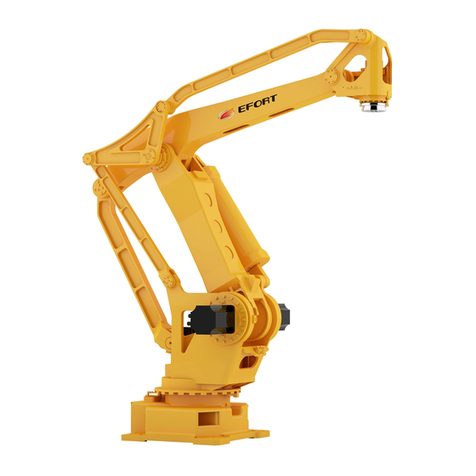
McConnel Robocut RC56 User manual

ROBOCUT
Publication 930
January 2019
Part No. 24214.30
Revision: 22.03.19 McCONNEL
Models RC56 & RC75
REMOTE CONTROLLED TRACTOR UNIT
Operator Manual

IMPORTANT
VERIFICATION OF WARRANTY REGISTRATION
DEALER WARRANTY INFORMATION & REGISTRATION VERIFICATION
It is imperative that the selling dealer registers this machine with McConnel Limited before
delivery to the end user –failure to do so may affect the validity of the machine warranty.
To register machines go to the McConnel Limited web site at www.mcconnel.com, log
onto ‘Dealer Inside’ and select the ‘Machine Registration button’which can be found in
the Service Section of the site. Confirm to the customer that the machine has been
registered in the section below.
Should you experience any problems registering a machine in this manner please contact
the McConnel Service Department on 01584 875848.
Registration Verification
Dealer Name:
……………………..…………………………………………………………….
Dealer Address:
…….………………………………………………………………………….
Customer Name:
……………………..…………………………………………………………
Date of Warranty Registration:
……/……/...…… Dealer Signature: ………………..……
NOTE TO CUSTOMER / OWNER
Please ensure that the above section above has been completed and signed by the selling
dealer to verify that your machine has been registered with McConnel Limited.
IMPORTANT: During the initial ‘bedding in’ period of a new machine it is the customer’s responsibility
to regularly inspect all nuts, bolts and hose connections for tightness and re-tighten if required. New
hydraulic connections occasionally weep small amounts of oil as the seals and joints settle in –where
this occurs it can be cured by re-tightening the connection –refer to torque settings chart below. The
tasks stated above should be performed on an hourly basis during the first day of work and at least
daily thereafter as part of the machines general maintenance procedure.
CAUTION: DO NOT OVER TORQUE HYDRAULIC FITTINGS AND HOSES
TORQUE SETTINGS FOR HYDRAULIC FITTINGS
HYDRAULIC HOSE ENDS
PORT ADAPTORS WITH BONDED SEALS
BSP
Setting
Metric
BSP
Setting
Metric
1/4”
18 Nm
19 mm
1/4”
34 Nm
19 mm
3/8”
31 Nm
22 mm
3/8”
47 Nm
22 mm
1/2”
49 Nm
27 mm
1/2”
102 Nm
27 mm
5/8”
60 Nm
30 mm
5/8”
122 Nm
30 mm
3/4”
80 Nm
32 mm
3/4”
149 Nm
32 mm
1”
125 Nm
41 mm
1”
203 Nm
41 mm
1.1/4”
190 Nm
50 mm
1.1/4”
305 Nm
50 mm
1.1/2”
250 Nm
55 mm
1.1/2”
305 Nm
55 mm
2”
420 Nm
70 mm
2”
400 Nm
70 mm


Warranty Policy (page 1 of 3)
WARRANTY POLICY
WARRANTY REGISTRATION
All machines must be registered, by the selling dealer with McConnel Ltd, before delivery to the end user.
On receipt of the goods it is the buyer’s responsibility to check that the Verification of Warranty
Registration in the Operator’s Manual has been completed by the selling dealer.
1. LIMITED WARRANTIES
1.01. All mounted machines supplied by McConnel Ltd are warranted to be free from defects in material
and workmanship from the date of sale to the original purchaser for a period of 12 months, unless a
different period is specified.
All Self Propelled Machines supplied by McConnel Ltd are warranted to be free from defects in
material and workmanship from the date of sale to the original purchaser for a period of 12 months
or 1500 hours. Engine warranty will be specific to the Manufacturer of that unit.
1.02. All spare parts supplied by McConnel Ltd and purchased by the end user are warranted to be free from
defects in material and workmanship from the date of sale to the original purchaser for a period of 6
months. All parts warranty claims must be supported by a copy of the failed part invoice to the end
user. We cannot consider claims for which sales invoices are not available.
1.03. The warranty offered by McConnel Ltd is limited to the making good by repair or replacement for the
purchaser any part or parts found, upon examination at its factory, to be defective under normal use
and service due to defects in material or workmanship. Returned parts must be complete and
unexamined. Pack the component(s) carefully so that any transit damage is avoided. All ports on
hydraulic items should be drained of oil and securely plugged to prevent seepage and foreign body
ingress. Certain other components, electrical items for example, may require particular care when
packing to avoid damage in transit.
1.04. This warranty does not extend to any product from which McConnel Ltd’s serial number plate has
been removed or altered.
1.05. The warranty policy is valid for machines registered in line with the terms and conditions detailed and
on the basis that the machines do not extend a period of 24 months or greater since their original
purchase date, that is the original invoice date from McConnel Limited.
Machines that are held in stock for more than 24 months cannot be registered for warranty.
1.06. This warranty does not apply to any part of the goods, which has been subjected to improper or
abnormal use, negligence, alteration, modification, fitment of non-genuine parts, accident damage,
or damage resulting from contact with overhead power lines, damage caused by foreign objects (e.g.
stones, iron, material other than vegetation), failure due to lack of maintenance, use of incorrect oil or
lubricants, contamination of the oil, or which has served its normal life. This warranty does not apply
to any expendable items such as blades, belts, clutch linings, filter elements, flails, flap kits, skids, soil
engaging parts, shields, guards, wear pads, pneumatic tyres or tracks.
1.07. Temporary repairs and consequential loss - i.e. oil, downtime and associated parts are specifically
excluded from the warranty.
1.08. Warranty on hoses is limited to 12 months and does not include hoses which have suffered external
damage. Only complete hoses may be returned under warranty, any which have been cut or repaired
will be rejected.
1.09. Machines must be repaired immediately a problem arises. Continued use of the machine after a
problem has occurred can result in further component failures, for which McConnel Ltd cannot be held
liable, and may have safety implications.
1.10. If in exceptional circumstances a non McConnel Ltd part is used to effect a repair, warranty
reimbursement will be at no more than McConnel Ltd’s standard dealer cost for the genuine part.

Warranty Policy (page 2 of 3)
1.11. Except as provided herein, no employee, agent, dealer or other person is authorised to give any
warranties of any nature on behalf of McConnel Ltd.
1.12. For machine warranty periods in excess of 12 months the following additional exclusions shall apply:
1.12.1. Hoses, exposed pipes and hydraulic tank breathers.
1.12.2. Filters.
1.12.3. Rubber mountings.
1.12.4. External electric wiring.
1.12.5. Bearings and seals
1.12.6. External Cables, Linkages
1.12.7. Loose/Corroded Connections, Light Units, LED’s
1.12.8. Comfort items such as Operator Seat, Ventilation, Audio Equipment
1.13. All service work, particularly filter changes, must be carried out in accordance with the manufacturer’s
service schedule. Failure to comply will invalidate the warranty. In the event of a claim, proof of the
service work being carried out may be required.
1.14. Repeat or additional repairs resulting from incorrect diagnosis or poor quality previous repair work
are excluded from warranty.
NB Warranty cover will be invalid if any non-genuine parts have been fitted or used. Use of non-genuine
parts may seriously affect the machine’s performance and safety. McConnel Ltd cannot be held
responsible for any failures or safety implications that arise due to the use of non-genuine parts.
2. REMEDIES AND PROCEDURES
2.01. The warranty is not effective unless the Selling Dealer registers the machine, via the McConnel web
site and confirms the registration to the purchaser by completing the confirmation form in the
operator’s manual.
2.02. Any fault must be reported to an authorised McConnel Ltd dealer as soon as it occurs. Continued use
of a machine, after a fault has occurred, can result in further component failure for which McConnel
Ltd cannot be held liable.
2.03. Repairs should be undertaken within two days of the failure. Claims submitted for repairs undertaken
more than 2 weeks after a failure has occurred, or 2 days after the parts were supplied will be
rejected, unless the delay has been authorised by McConnel Ltd. Please note that failure by the
customer to release the machine for repair will not be accepted as a reason for delay in repair or
submitting warranty claims.
2.04. All claims must be submitted, by an authorised McConnel Ltd Service Dealer, within 30 days of the
date of repair.
2.05. Following examination of the claim and parts, McConnel Ltd will pay, at their discretion, for any valid
claim the invoiced cost of any parts supplied by McConnel Ltd and appropriate labour and mileage
allowances if applicable.
2.06. The submission of a claim is not a guarantee of payment.
2.07. Any decision reached by McConnel Ltd. is final.
3. LIMITATION OF LIABILITY
3.01. McConnel Ltd disclaims any express (except as set forth herein) and implied warranties with respect to
the goods including, but not limited to, merchantability and fitness for a particular purpose.
3.02. McConnel Ltd makes no warranty as to the design, capability, capacity or suitability for use of the
goods.
3.03. Except as provided herein, McConnel Ltd shall have no liability or responsibility to the purchaser or
any other person or entity with respect to any liability, loss, or damage caused or alleged to be caused
directly or indirectly by the goods including, but not limited to, any indirect, special, consequential, or
incidental damages resulting from the use or operation of the goods or any breach of this warranty.
Notwithstanding the above limitations and warranties, the manufacturer’s liability hereunder for
damages incurred by the purchaser or others shall not exceed the price of the goods.
3.04. No action arising out of any claimed breach of this warranty or transactions under this warranty may
be brought more than one (1) year after the cause of the action has occurred.

Warranty Policy (page 3 of 3)
4. MISCELLANEOUS
4.01. McConnel Ltd may waive compliance with any of the terms of this limited warranty, but no waiver of
any terms shall be deemed to be a waiver of any other term.
4.02. If any provision of this limited warranty shall violate any applicable law and is held to be
unenforceable, then the invalidity of such provision shall not invalidate any other provisions herein.
4.03. Applicable law may provide rights and benefits to the purchaser in addition to those provided herein.
McConnel Limited

DECLARATION OF CONFORMITY
Conforming to EU Machinery Directive 2006/42/EC
We,
McCONNEL LIMITED, Temeside Works, Ludlow, Shropshire SY8 1JL, UK
Hereby declare that:
The Product; Radio Controlled Tracked Tractor Unit
Product Code; RMOW
Serial No. & Date ………………………………… Type …………………………
Manufactured in; United Kingdom
Complies with the required provisions of the Machinery Directive 2006/42/EC
The machinery directive is supported by the following harmonized standards;
■BS EN ISO 12100 (2010) Safety of machinery –General principles for design –Risk
assessment and risk reduction.
■BS EN 349 (1993) + A1 (2008) Safety of machinery - Minimum distances to avoid the
entrapment with human body parts.
■BS EN ISO 14120 (2015) Safety of machinery - Guards general requirements for the
design and construction of fixed and movable guards.
■BS EN 4413 (2010) Hydraulic fluid power. Safety requirements for systems and their
components.
McCONNEL LIMITED operates an ISO 9001:2008 quality management system,
certificate number: FM25970.
This system is continually assessed by the;
British Standards Institution (BSI), Beech House, Milton Keynes, MK14 6ES, UK
BSI is accredited by UK Accreditation Service, accreditation number: UKAS 003.
The EC declaration only applies if the machine stated above is used in
accordance with the operating instructions.
Signed …………………................ Responsible Person
CHRISTIAN DAVIES on behalf of McCONNEL LIMITED
Status: General Manager Date: January 2018

For Safety and Performance…
ALWAYS READ THE BOOK FIRST
In line with our policy of constant improvement, this publication will be periodically
updated; to ensure you have access to the latest version of this manual please
visit the manuals library on our website where an ‘up-to-date’ version can be
referenced online, or downloaded.
http://dealerinside.mcconnel.com/dealerinside/Parts/PDFManuals/pdf/Manuals/Robocut/
ROBOCUT%20RC56%20&%20RC75%20Operator%20Manual.pdf
McCONNEL LIMITED
Temeside Works
Ludlow
Shropshire
England
Telephone: +44 (0)1584 873131
www.mcconnel.com

CONTENTS
General Information .............................................................................................................1
Machine Description – Robocut RC56 & RC75 ...................................................................2
Machine Identification ..........................................................................................................2
Undercarriage Specifications ...............................................................................................3
Features & Specifications – RC56 Model ............................................................................4
Features & Specifications – RC75 Model ............................................................................5
Flailhead Use - Important Information..................................................................................6
Safety Information................................................................................................................6
Machine Delivery ...............................................................................................................10
Machine Overview .............................................................................................................12
Emergency Stop Buttons (E-Stop).....................................................................................14
Safety Devices & Emergency Stop (E-Stop)......................................................................15
Remote Control Unit ..........................................................................................................16
Control Panel .....................................................................................................................19
Screen Access...................................................................................................................20
Settings Menus ..................................................................................................................21
Job Timer Settings .......................................................................................................21
Attachment Settings .....................................................................................................22
Robo Aux......................................................................................................................23
Float Settings – Automatic Calibration..........................................................................25
Float Settings – Manual Adjustments ...........................................................................26
Front Hood Activate / Deactivate Settings ....................................................................27
Joystick Function Swap & Travel Swap Settings..........................................................28
Reversing Fan Settings ................................................................................................30
Warning & Error Screens..............................................................................................31
Information Screens .....................................................................................................32
Machine Information.....................................................................................................32
Service History .............................................................................................................32
Service Screen .............................................................................................................33
Service Verification.......................................................................................................34
Lights Settings..............................................................................................................36
Service Settings ...........................................................................................................38
Pre-Operation Checks .......................................................................................................40
Starting & Stopping the Engine..........................................................................................41
Driving & Manouevering.....................................................................................................43
Operating Position & Distance ...........................................................................................46

Operation...........................................................................................................................48
Track Types & Options ......................................................................................................50
Undercarriage Components...............................................................................................51
Track Replacement............................................................................................................53
Track Removal Procedure.................................................................................................53
Support Springs.................................................................................................................54
Reversible Fan...................................................................................................................54
Emergency Control Unit (Get Me Home)...........................................................................55
Charging Station For Remote Control Battery ...................................................................56
Troubleshooting.................................................................................................................57
Fuses & Relays..................................................................................................................58


1
GENERAL INFORMATION
Read this manual before fitting or operating the machine or accessory. Whenever any
doubt exists contact your local dealer or the McConnel Service Department for assistance.
Only use ‘Genuine McConnel Parts’ on McConnel machinery and equipment.
DEFINITIONS: The following definitions apply throughout this manual;
DANGER: Alerts to a hazardous situation which will result in death or serious injury if not
observed carefully.
WARNING: Alerts to a hazardous situation which could result in death or serious injury if
not observed carefully.
CAUTION: Alerts to a hazardous situation which could result in damage to the machine
and/or equipment if not observed carefully.
NOTICE: Specific or general information considered important or useful to emphasise.
LEFT HAND (LH) & RIGHT HAND (RH): These terms are applicable to the machine when
fitted to the tractor and viewed from the rear; these terms also apply to tractor references.
SERIAL PLATE
All machines are equipped with a serial number plate containing important information
relating to the machine including a unique serial number used for identification purposes.
Note: Images in this manual are provided for instruction and informational purposes only and may
not show components in their entirety. In certain instances images may appear different to the
actual machine; where this occurs the general procedure will be basically the same. E&OE.
NOISE LEVEL
LpA = the value indicates the maximum sound level perceived by the operator at a
distance of 1m from the machine.
LwA = the value indicates the sound level outside the machine and refers to the noise
perceived by those who are in the vicinity of the work area.

2
MACHINE DESCRIPTION – ROBOCUT RC56 & RC75
The McConnel Robocut RC56 & RC75 machines are all-terrain, remote controlled, tracked
vehicles for use as versatile work platforms for a comprehensive range of attachments.
Machines feature powerful 56HP or 75HP fuel-efficient Hatz diesel engines mounted on
‘low centre of gravity’ chassis with perfect 50/50 weight distribution that provide maximum
stability and excellent performance on all types of terrain and the ability of operating on
slopes of up to 55°.
The RC56 & RC75 models are controlled via precision digital remote control units giving
users the freedom to operate the machines in difficult and dangerous areas at distances of
up to 150m.
MACHINE IDENTIFICATION
Machine and engine identification plates are fitted to the left-hand track plate of the
machine in the locations indicated below, a matching engine identification plate is also
located on the engine unit itself.
It is advisable that owners keep a record of the serials number of both machine and engine
as stated on these identification plates and always quote serial numbers when ordering
replacement parts or when seeking service information and/or advice.
MACHINE & DEALER INFORMATION
Record serial numbers and dealer contact information here. Always quote serial numbers
when ordering replacement parts or seeking service information and/or advice.
Machine Serial Number: Machine Installation Date:
Engine Serial Number:
Machine Model Details:
Dealer Name & Branch:
Dealer Address:
Dealer Telephone No:
Dealer Email Address:
Machine
Identification
Pl
ate
Engine
Identification
Pl
ate

3
UNDERCARRIAGE SPECIFICATIONS
RC56 & RC75 Undercarriage Specifications
Loading Capacity 1.2T
Length 1548mm
Axle to axle length 1192mm
Track height 479.5mm
Cross-member height (from ground) 150mm
Fixed undercarriage width 1260mm
Number of lower rollers per side (per machine) 4 + 4 (8)
Number of upper rollers per side (per machine) 1 + 1 (2)
Track width 230mm
Number of links per side (per machine) 47 + 47 (94)
Chain pitch 72mm
Track tensioner pressure (Max) 150Bar
Total weight 444kg
Hydraulic motor displacement 332cm³
Hydraulic motor pressure (Max) 190Bar
Hydraulic flow rate (Max) 39l/min
Maximum speed 7km/h
Operating temperature range -10/+40°C
Maximum operating humidity 95%
Brake release pressure range 12-16Bar
Maximum grade ability 114%

4
FEATURES & SPECIFICATIONS – RC56 Model
ROBOCUT RC56
○56HP (42kW) 3 Cylinder Hatz Diesel Engine
○Tracked carriage closed hydraulically piston pump
○Track tensioning pre-set to 150bar Max
○Remote controlled operation (up to 150m range)
○3 options of rubber tracks
○Potentiometer forward speed control from 0 to 100%
○Potentiometer hydraulic power control from 0 to 100%
○Independent Cooling System for Hydraulic Circuits
○Self-Cleaning Reversible Fan
○Customisable work and driving light system
○Proportional lift and lower with float function
○2 Auxiliary hydraulic services up to 16litre/min
○Main hydraulic power
59litre/min @ 350bar
○Proportional joystick speed control : Forwards & Backwards (2 speed)
Speed 1: 0 to 3.5 km/h
Speed 2: 0 to 7.0 km/h
○38 Litre Fuel Tank Capacity
○1300mm Carriage Width
○Machine Weight (less fuel): 1180kg
56HP

5
FEATURES & SPECIFICATIONS – RC75 Model
ROBOCUT RC75
○75HP (56kW) 4 Cylinder Hatz Diesel Engine
○Tracked carriage closed hydraulically piston pump
○Track tensioning pre-set to 150bar Max
○Remote controlled operation (up to 150m range)
○3 options of rubber tracks
○Potentiometer forward speed control from 0 to 100%
○Potentiometer hydraulic power control from 0 to 100%
○Independent Cooling System for Hydraulic Circuits
○Self-Cleaning Reversible Fan
○Customisable work and driving light system
○Proportional lift and lower with float function
○2 Auxiliary hydraulic services up to 16litre/min
○Main hydraulic power
95litre/min @ 350bar
○Proportional joystick speed control : Forwards & Backwards (2 speed)
Speed 1: 0 to 3.5 km/h
Speed 2: 0 to 7.0 km/h
○38 Litre Fuel Tank Capacity
○1300mm Carriage Width
○Machine Weight (less fuel): 1280kg
75HP

6
On machines mounted with a grass flailhead,
the hood warning screen will always be
displayed on start-up; it is the operator’s
responsibility to ensure all safety conditions
are met before selecting the option to activate
the hood. Operators of this machine are
responsible for the safety of all persons and
property in the vicinity of the working
machine; if doubt exists work should only be
performed with the hood de-activated.
FLAILHEAD USE - IMPORTANT INFORMATION
‘As Supplied’
The flailhead is fitted with a hydraulic ram to allow movement of the hinged hood, by
default on every start-up movement of this ram is electronically deactivated to stop
operators inadvertently opening the hood when cutting alongside the highway; this
reduces the risk to passing traffic from being hit by objects ejected at speed from the
working flail head. It should be noted that with the hinged hood opened objects could be
thrown a considerable distance. Being struck by a thrown object could result in injury or
death.
If the machine is being used away from the highway, where other vehicles and bystanders
are not normally in the vicinity, the hood ram function may be activated provided the
general safety information and following specific conditions are met;
A detailed work area and bystander risk assessment is undertaken before work begins.
The operator has been trained in the safe use of the Robocut.
All pre-work checks stated in this manual have been fully performed.
By default, the hood ram on a flailhead is
electronically de-activated at every start-up
to prevent inadvertent opening of the hood
when working in the vicinity of highways
and public areas; it must never be activated
when operating in these types of areas.

7
SAFETY INFORMATION
This machine and any attached equipment has the potential to be extremely dangerous -
in the wrong hands it can kill or maim; It is therefore imperative that both owner and
operator of the machine reads the following section to ensure they are fully aware of the
dangers that do, or may exist, and fully understand their responsibilities surrounding use
and operation of this machinery.
The operator of this machine is responsible not only for their own safety but equally for the
safety of all others who may come into the close proximity of the machine, as the owner
you are responsible for both.
When the machine is not in use it should be parked on a firm level site with any mounted
equipment at rest on the ground with the isolator key removed.
In the event of any fault being detected with the machine’s operation it must be stopped
immediately and not used again until the fault has been corrected by a qualified technician.
Before starting the machine the operator must read and understand all aspects of use
and maintenance of the machine as stated in this manual.
The machine must only be used by a responsible adult who is familiar with all aspects
relating to safe operation. Certificated training may be required on certain sites.
The machine must not be operated by children or non-authorised persons.
Operators must know the meaning of all operation and safety decals on the machine,
the mounted attachments, and the remote control unit.
Operators must know the correct procedure for switching the machine off normally and
know the locations of all Emergency Stop buttons.
Do not attempt to use the machine if any of the Emergency Stop buttons are damaged
or malfunctioning.
Never use the machine with safety guarding removed or defective.
Operators should practice operation on flat open ground to familiarise themselves with
driving and manoeuvring the machine before attempting to use it on sloping ground.
Operators should practice manoeuvring the machine around obstacles, without the
mounted equipment running, before using the machine for work purposes.
Never operate the machine if your vision is blocked or obscured by obstacles such as
vehicles, buildings, hedges, fences etc.; move to a safe position where you have a
clear, un-interrupted view of the entire machine.

8
Never operate the machine when standing directly in the line of travel.
Do not use the machine on sand piles, gravel, or other similar loose materials.
Only operate the machine in good light conditions.
Never start or run the machine in an enclosed area or building.
Keep the machine clean to avoid build ups of dry materials that could ignite on hot
components.
Never stand directly below a machine that is working or parked on a slope.
Always operate the joystick control slowly; rapid or jerky movements could cause the
machine to ‘rear up’ causing loss of control.
When operating the machine with the flail head running the operator must remain in a
safe position at least 5 metres away from the machine; always switch the flail head off
before approaching the machinery.
When using the machine the operator should place themselves in a position that
provides optimum visibility over the entire work area.
Never leave a running machine unattended; always switch the engine off and remove
the isolator key.
Always stop and switch the machine off if persons or animals enter the work area; do
not restart the machine until they are at a safe distance.
Never use the machine to perform tasks it was not designed for.
Never ride or allow others to ride on the machine.
Always inspect the work area prior to operation and remove stones, glass, metal, wire
or any other foreign objects that are hazardous. Immovable hazards should be suitably
‘marked’ so they can be easily avoided.
Take extra care when operating the machine on slopes or uneven ground; there is
increased risk of objects being thrown from rotating equipment when working in these
conditions.
The machine can be used on slopes up to a maximum of 55° (track option dependant)
providing the surface is dry and firm.
Should a machine overturn, a suitable crane or winch should be used to recover it;
keep all persons at a safe distance before and during recovery.
Do not operate the machine in foggy or frosty conditions as there is increased risk of
accidents.
Take extra care when working in close proximity to electrical cables; in some
circumstances, operating the machine under overhead power lines can result in loss of
radio signal causing the engine to be deactivated.
Do not operate the machine close to vehicles or properties where there is risk of
damage by objects accidentally ejected from certain types of mounted equipment.
It is the user’s responsibility to protect persons in or near the work zone.
When servicing or maintaining the machinery no-one should be allowed beneath it
when it is raised unless it is securely supported on suitable ramps or stands.
Never attempt to service or maintain the machine whilst it is running; always switch off
the engine and remove the isolator key.

9
When transporting the machine on another vehicle or trailer the engine must be
switched off and the machine chocked and secured with suitable ropes or chains.
Check the condition of any flails or other mounted tools and their fixings on a regular
basis; never use a machine with damaged or missing flails/tools or loose fixings.
Always clean the machine after use; if machine components are hot allow them to cool
to a safe temperature before cleaning. Never use solvent based chemicals for cleaning.
When operating in excessively dusty conditions the machine may need to be stopped
on a regular basis to remove any build ups of dust on components that could cause
overheating; switch the engine off and beware of hot components.
Ensure engine is switched off and Emergency Stop switch is in the ‘off’ position before
refuelling.
Wherever possible refuel the machine before work when the engine is cold. If refuelling
during work, switch off the engine and allow it to cool before adding fuel.
Test the Emergency Stop buttons before each period of work to ensure they function
correctly.
Never leave the machine, isolator key and control unit unattended in one place; the
machine could be started and used by un-authorised persons.
Any inspection, service or maintenance of the machine and attached equipment must
only be performed with machine switched off and the isolator key removed.
Always wear suitable safety gear at all times when performing service or maintenance
work on the machine or any mounted equipment.
Mounted equipment must always be switched off when manoeuvring outside of the
work zone.
Personal Protective Equipment (PPE)
We recommend that the following personal protective equipment is worn during operation
and/or maintenance of this machinery; overalls, safety shoes, safety goggles, ear
protection, safety helmet, protective gloves, respiratory protection, shin/knee protection.
Although the information stated here covers a wide range of safety subjects, it is impossible to
predict every eventuality that can occur under differing circumstances whilst operating this machine.
No advice given here can replace ‘good common sense’ and ‘total awareness’ at all times, but it will
go a long way towards the safe use of your McConnel machine.
Operating, servicing and maintaining this equipment can
expose you to chemicals including gasoline, diesel fuel,
lubricants, petroleum products, engine exhaust, carbon
monoxide, and phthalates, which are known to the State of
California to cause cancer and birth defects or other
reproductive harm. To minimize exposure, avoid breathing exhaust, do not idle the engine except as
necessary, service your vehicle in a well-ventilated area and wear gloves or wash your hands
frequently when servicing your vehicle. Battery posts, terminals and related accessories contain lead
and lead compounds, chemicals known to the state of California to cause cancer, birth defects or
other reproductive harm. For more information go to www.P65Warnings.ca.gov. This website,
operated by California's Office of Environmental Health Hazard Assessment, provides information
about these chemicals and how individuals may be exposed to them.
This manual suits for next models
1
Table of contents
