McCormick-Deering Farmall F-14 User manual

Farmall
F-14
Tractor

I.
Before starting
a
new
engine, remove
the
spark
plu
rr
and
put
abut
OW
ounct
of
gas
engine lubricating oil into
each
cylinder;
replace
the
spark
dugs
and mnk
the
engine
to
distribute
the
ail
over
the
cylinder
walfs.
2.
During
the
first
one
hundred hours
of
o
ration,
mix
one
pint
d
engine
oil
with
every
Sive
gallons
of
fd.
table
for
"running
in"
a
new engine.
B
in#
66
drained
cempletefg
undJillEd
with
oil
as
the
4.
Tmctm
IOI
United
5.
CsmgJete instructions
for
oilin
are
showrr
on
"Lubrication
Chart."
6.
Do
nd
&or
i
be
Imded
t
ntif
it
Do
not owrlez%d
the
Tril6tor
at
any
time
or
when
new
lugs
are
wt
intends
in
order
ve
the right
to
make
changttg
in
a
cr
add
any
impvemults without
incurring
the
obligation
to
instdl
such
ch
an
Tractors
prcGclusly
purchased.
This
book
contains, addition
to
instructions
for
iffusitrntions pertainin
to
certain
simple
adjustmen
can readily
be
made.
owever,
the
owner
&auld
am
endoverhauling
or
ry
equipment fof
doin
Avoid
Accidents
Most accidents, whether they occur in industry, on the farm,
at home, or on the highway, are caused
by
the failure of some
individual to follow simple and fundamental safety rules or
precautions. For this reason most accidents can
be
prevented
by recognizing the real cause and doing something about it before
the accident occurs.
Regardless of the care used in the design and construction of
any type of equipment, there are many conditions that cannot
be
completely safeguarded against without interfering with reasonable
accessibility and efficient operation.
A
careful operator is the best insurance against an
accident.
The complete observance of onc?simple rule would pre-
vent many thousand serious injuries each year. That rule
is: C'Nenerattempt to clean,oil, or adjust a machine while
it is
in
motion."
NATIONAL
SAFETY
COUNCIL
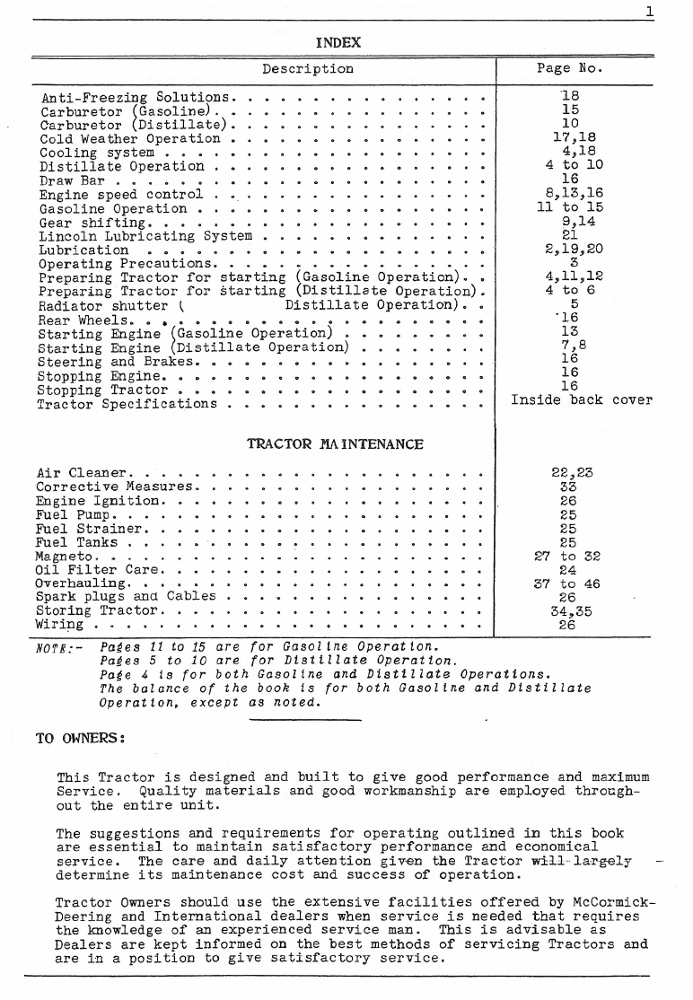
INDEX
Description
................
Anti-Freezing Solutions
.................
Carburetor ~asoline)
................
Carburetor [Distillate)
................
Cold Weather Operation
....................
Cooling system
.................
Distillate Operation
.......................
Draw Bar
.................
Engine speed control
..................
Gasoline Operation
.....................
Gear shifting
..............
Lincoln Lubricating System
Lubrication
.....................
.................
Operating Precautions
Preparing Tractor for starting (Gasoline Operation)
.
.
Preparing Tractor for starting (Distillate Operation)
.
Radiator shutter
(
Distillate Operation)
..
.....................
Rear Wheels
.........
Starting Engine Gasoline operation)
........
Starting Engine Distillate Operation)
..................
Steering and Brakes
....................
Stopping Engine
...................
Stopping Tractor
................
Tractor Specifications
TRACTOR
INTENANCE
......................
Air
Cleaner
..................
Corrective Measures
Engine Ignition
....................
Fuel Pump
.......................
.....................
Fuel Strainer
Fuel Tanks
......................
Magneto
........................
....................
Oil
Filter Care
Overhauling
......................
................
Spark plugs and Cables
Storing Tractor
....................
Wiring
........................
NOTE.--
Pages
11
to
15
are for Gasol lne Operat ion
.
Pages
5
to
10
are for Distillate O~eration
.
Page No
.
16
Inside back cover
page
6
is for both'~aso1tneand ~isti~~ateOperations
.
The balance of the book is for both Gasoline and Dlstillate
Operat ion. except as noted
.
TO
OWNERS:
This Tractor
is
designed and built to give good performance and maximum
Service
.
Quality materials and good workmanship are employed throcgh-
out the entire unit
.
The suggestions and requirements for operating outlined in this book
are essential to maintain satisfactory performance and economical
service
.
The care and daily attention given the Tractor
will
largely
.
determine
its
maintenance cost and success of operation
.
Tractor Owners should use the extensive facilities offered by McCormick-
Deering and International dealers when service
is
needed that requires
the knowledge of
an
experienced service man
.
This
is
advisable as
Dealers are kept informed on the best methods of servicing Tractors and
are in a position to give satisfactory service
.

LUBRICATION
S.
1.
1.
Numbers or weights of oil and lubricants recommended.
I
I
Engine
Crankcase
Summer
Magneto
&
Very Light,
Cream Sep.
or Sewing
Machine
Oil
Lubricating
Fittings
Approved
Lubricant
SAE-160
Cleaner
SAE-20
Lighter
Winter SAE-10-W
SAE-20-W
Very Light,
cream sep.
1
ipproiedpFSAE-20
-1
or Sewing Lubricant
Machine SAE-90 Lighter
Oil*
*
Use kerosene in magneto coupling during cold weather.
CautionC Be sure to use a mineral oil for lubrtcating the gng.tne.
Do
not use top cylinder or valve oils.
Note: Engine lubricating oil shall be of well refined oils, free
from water, sediment, acid, resin or any other substance not
derived from petroleum.
Oil
shall not corrode any metal used in
engine construction.
Never check ott level whtle engine is running.
Proper lubrication is very important and instructions should be followed
closely. (See llLubrication Chart").
(See Special Instructions for Cold Feather Operation on pages
17
and
181.
TRANSMISSION, STEERING
GEAR
CASE,
FRONT AND
REAR
WHEELS, ETC.
Transmission Steering Gear Front and Rear
I
Case
I
Case Wheels, ~tc.
I
Summer Approved
Lubricant
SAE-160
See Instructions on page
20
for filllnl Rand-Lubrlcator.
Winter
The lubricant used for Transmissions, etc., Alemtte, Lincoln or Zerk
System should be a good grade of oil and conform to the fo2Zowlng
-
Approved
Lubricant
SAE-160
SAE-160 should be used when minimum temperature is above 40' F.
SAE-90 should be used when minimum temperature
is
below 40° F.
Approved
Lubricant
SAE-160
Approved
Lubricant
SAE-SO
The preferred lubricant should be made from mineral oil and should be
free from solid materials, which are undesirable
for
ball or roller bear-
ing lubrication.
Approved
Lubricant
SAE-90
Approved
Lubricant
SAE-90

3
OPERATING PRECAUTIONS
Read Instruction Book carefully.
Follow 'Lubricatton,Chart.
"
Before cranking tractor engine, be sure:-
I.
Gear shift lever is in neutral position.
2.
Radiator is filled with water.
3.
Englne has sufficient oil in crankcase pan.
When cranking the engine, retard spark control. Operator
should take his position so as to avotd being struck by starttng crank
if there is a reversal of the direct ion of the engine from any cause
whatsoever.
Khen starting the Tractor always engage clutch gradually. so engtne will
pick up the load slowl~.This is parttcularly necessary when going up
a steep hill, cl imbtng out of ditches or when hitched to a heavy or
difficult lood. Never hitch to a stump or other object by means of a
lbnC chain or rope with slack so that when Tractor moves forward it will
jerk into the lood.
Never operate engtne at more than the regu
speeds are dangerous.
Warning:-
Do not hitch to the tractor at any poin
Do not attempt to vull when draw bar is
Always use draw bar and braces.
1
ar governed speed. Excess ive
t except to the draw bar.
removed.
Drawbar and braces must be kept tight.
Never
funnel
avoid
carefu
radius
f
t11 pasol ine
t
ank when near an open
f
1
one or engtne is running. Beep
in contact with metal of fuel tank when pourlnp tn fuel, to
posstbtllty of an electric spark tgnltlng the gas. Be very
1
about lighting matches near gasoline, as the air within the
of several feet 1s permeated with a highly
explosive
vapor.
Cars should be exercised when Tractor is in motlon to prevent accidents
and personal tnjurles,
Do not use the clutch pedal as a foot rest; this causes undue wear on
clutch parts.
Never pour cold water into radiator if engine is hot.
Do not overload the Tractor at any t tme.
When pneumat ic tires are used, keep correct air pressure in
t
tres.
Clean breather in right hand side of value housing every week as
instructed.
IOTB:
Be sure to read instructlons on "SPGCIAL PRECAUTIONS KITE
A
XEY
TRACTOR" gives on back of front cover.
9
GASOLINE
OR
DISTILLATE
OPERATION
Paratraphs are numbered to correspond with numbers on
the
tllustratlons.
PREPARATIONS FOR START
I
NG
LUBRICATION
/See "Lubrlcat ton Chart').
Oil
magneto.
Check oil level of air cleaner.
Check oil level of engine crankcase.
Check oil level of transmission case.
Check oil level of steering gear case.
Check Tractor carefully with "Lubrication Chart1'.
If any lubrication connections are missing, replace
before starting.
Lubricate each place throughout entire Tractor as
instructed on "Lubrication Chartn.
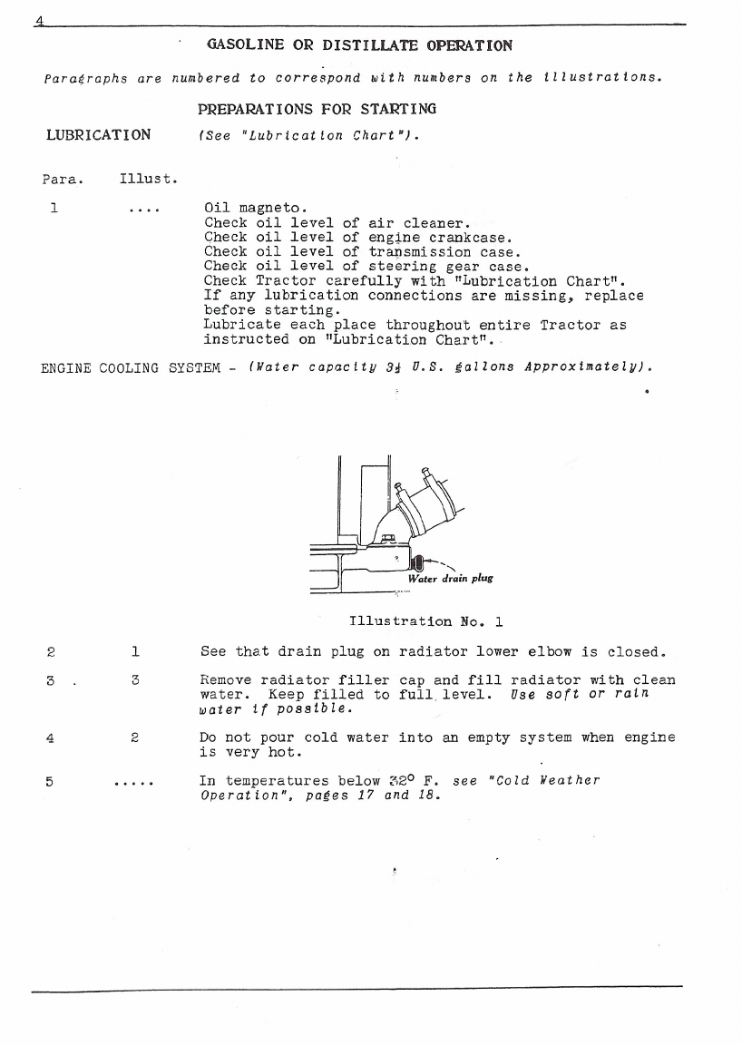
ENGINE COOLING
SYSTEM
-
(Hater capoclty
3&
U.S.
gallons Approximately).
Illustration
No.
1
See that drain plug on radiator lower elbow
is
closed.
Remove radiator filler cap and
fill
radiator with clean
water. Keep filled to full level.
Use soft or rain
water
tf
possible.
Do not pour cold water into
an
empty system when engine
is very hot.
In
temperatures below
320
F.
see "Cold Weather
Operat ion". pages
17
and
18.

DISTILLATE OPERATION
Paragruphs
ore
numbered
to
correspond
aith
numbers
on
the tilustrations.
PREPARATIOHS
FOR
STARTING
-
Clntinved
P~r6.
Ill~~t.
6
..
...
NOTE:
Provision is made in the design of this engine to
use gasoline
as
fuel
and
can be operated on distillate
ty
applicetion of specis1 equipment listed for Pistillate
overation (See Psrts List.).
Ec~nomicelusc
of
distillate Tequires different operating
care
of
the engine. Folloa instructions to obtain best
results.
Before
ch&ngine
to distillate, SIloW encine to thorouehly
warm up. Five to eight minutes
ar
more
are
usuillj
ceress~ry
depending
an
itmospheric t,emperature.
WllTERFPGHT
Grrrn
2
%
2A
To
assist in warming up a
cold engine quickly, close
the winterfront (shutter)
completely (by turning
control handle all the
way
to the left
-
counter-
clockwise).
When heat indicator begins
to show "Hot", Own shutter
just enough
56
a;
to main-
tain the operating temper-
ature on the high side of
the working range
(on
neat
indicator).
Illustration
No.2
Heat Indicptor
2A
Adjustment of winterfront
rill
vary according to tractor
load, long periods
af
idling,
or
atmospheric temperature.
XOTB:
Distillate fuels are heavier than gasoline and
require more heat for proper vaporization.
Illustration
120.
7A
0
iA
Iaportont:
Do not start the engine in freezing reather
Without first closing the winterfront com2letely.
10 If engins
misses
ar
in
slow to accelerste
when
strrting,
it
1s
likely
not
hot enough to run on distillate.
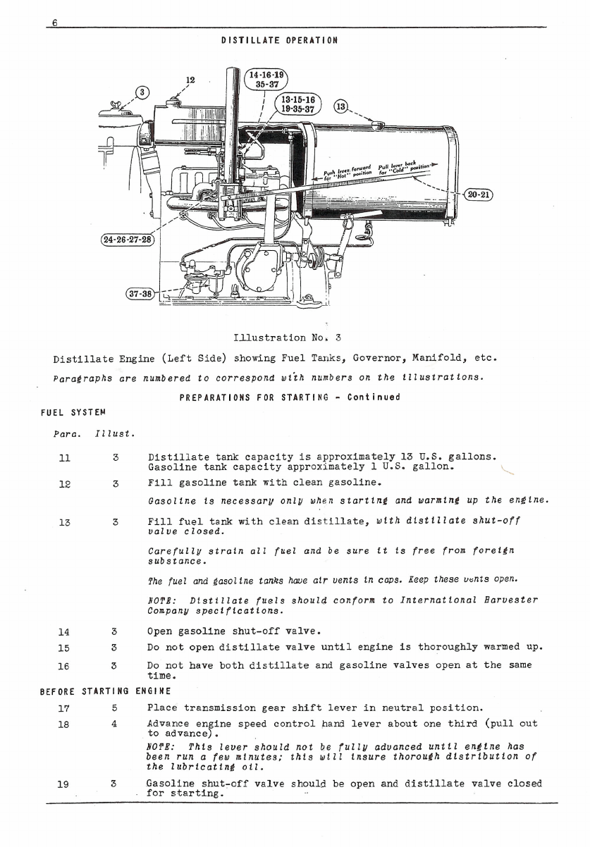
DISTILLATE OPERATION
Illustration No,
3
Distillate Engine (Left Side) showing Fuel Tanks, Governor, Manifold, etc.
~aragraphsare
FUEL SYSTEM
Para. I1lust.
11
3
12
3
numbered to correspond wiih numbers on the illustrations.
PREPARATIONS FOR STARTING
-
Continued
Distillate tank capacity
is
approximately 13
U.S.
gallons.
Gasoline tank capacity approximately
1
U.S.
gallon.
Fill gasoline tank with clean gasoline.
Gasoline is necessary only when starting and warming up the engine.
Fill fuel tank with clean distillate,
with distillate shut-off
value closed.
Carefully strain
011
fuel and be sure it
is
free from foreign
substance.
The fuel and gas01 ine tanks have air uents in caps. Ieep these u&S open.
NOTB:
Distillate fuels should confora to International Baruester
Company specipicat ions.
Open gasoline shut-off valve.
Do not open distillate valve until engine
is
thoroughly warmed up.
Do not have both distillate and gasoline valves open at the same
time.
BEFORE STARTING ENGINE
17
5
Place transmission gear shift lever in neutral position.
4
Advance en ine speed control hand lever about one third (pull out
to advance$.
NOTB:
This lever should not be fully aduanced until engine has
been run a few mtnutes; this wtll insure thoraufh distribution of
the lubricating oil.
19
3
Gasoline shut-off valve should be open and distillate valve closed
.
for starting.

DISTILLATE OPERATION
Paragraphs arz numbered to correspond with numbers on the tllustrations.
MANIFOLD HEAT
CONTROL
Para. Illust
.
20
3
Push the manifold heat control lever on left side of
fuel tank forward all the way. This sets the heat
control valve on manifold, in "Hotn
or
starting posi-
tion.
It ts important that control lever be properly
set to correspond with fuel being used and operating
conditions.
When starting on gasoline and operating.on distillate,
it
will
be desirable to keep the valve in "Hot"
position most of the time unless the weather is very
hot. In hot weather with a heavy load on the
engine, good results may be obtained with this valve'
in intermediate or "Cold11 position, but generally,
better results
will
be secured if the intake manifold
is
kept hot when using distillate. If not kept hot,
fuel
will
not be properly vaporized and dilution of
the crankcase lubricating oil, as well as imperfect
regulation of engine will result.
...
NOTE:-
If engine is to be operated when temperatures
are below 3Z0
F.,
see special instructions for Cold
Weather Operation. pages
17
and
18.
TO
START
ENGINE
23
4
Retard spark by moving spark control lever all the
way to the left.
3
Push up on the choke rod all the way.
....
When engine is cold and magneto grounded, crank engine
rapidly three or four revoluttons.
3
and
4
Move spark lever to starting position, about one-
quarter open, move choke rod one-half open and crank
engine using quick up-strokes until engine starts. The
use of choke for starting
will
vary depending on temper-
ature and altitude.
Do not use choke to enrich fuel mixture except when
starting the engine.
h'ever operate engine with choke
partly on.
As
soon as engine starts, the choke should be adjusted
to where the engine runs without missing,
and as the
engine warms up the choke should be gradually opened
all the way.
Advance spark control lever.
NOTE:-
Do not start the engine with the spark lever
ful ly advanced, as there is danger of a "back-fire" or
"kick" uhich may injure the operator.
....
See that oil pressure indicator is registering pressure.

DISTILLATE OPERATION
Sprh
leuer
(starting position)
Illustration No.
4
-
Engine.Controls.
Paragraphs are numbered to correspond with numbers on the
illustrations.
TO
START ENGINE
-
Continued
Para. Illust.
....
Should engine stop on distillate,it can be
started by cranking if it is hot enough.
.
.
.
.
If enzine has been stopped on distillate and is cold,
close distillate shut-off valve and drain carburetor
fuel bowl.
Then
proceed in accordance with starting
engine instructions.
.
If difficulty is experj.enced,see Correctfue Xeasures,
on page
33.
EilGINE SPEED CONTROL
Since the governor maintains constant engine speed
under variable loads, the engine speed control hand
lever should be used only to reduce the speed of
the engine below normal operating speed; with
engine speed control hand lever retarded, very
little load can be handled by the engine.
AFTER
ENGINE
IS
WARMED
UP
35
3
After engine
is
thoroughly warmed up, change over
to operate on distillate by closing gasoline shut-
off valve tight, and quickly open distillate
valve.
Never have both valves .open, or partly open, at the
same tine, otherwise distillate wtl2 mix with gaso-
line, making
it
unsatisfactory for starting.
36
4
Advance spark and engine speed control levers for
load to
be
handled.

DISTILLATE
OPERATION
Para2raphs are nunbered to correspond with numbers on the tllustralions.
TO
STOP ENGINE
Para. Illust.
37
S
Close distillate shut-off valve and immedihtely
open gasoline valve.
Run
engine on gasoline
2
or
3
minutes, long enough to empty fuel lines of
distillate and fill lines and fuel bowl with
gasoline. This
will
insure having gasoline in
the fuel bowl for starting.
Close fuel shut-off valve.
Set spark control to full retz.rd position.
Note:- It
ts
important that the fuel bowl
is
not
filled
ulth
distillate when engine 1s started as
this
makes the engine difficult, and under most
conditions Impossible to start.
39
.....
The engine can be stopped quickly in emer-
gencies
by
retarding spark all the
way.
dote:-
If
adjustment
of
the
carburetor should be
necessary,
follow
the instructions on
age
10.
START
49
TRACTOR
.,...
Place left foot on clutch pedal and press down
firmly, holding in this position;
this
disengages
the clutch. Clutch must always be disengaged while
shifting gears.
Nove gear shifting lever to desired speed.
Gently release pressure on clutch pedal; this
engages clutch
and
causes tractol- to move. Do not
drive with foot resting on clutch pedal.
GEAR
SHIFTING
1
43
b;
5
Aluays disengage clutch before
maktrlg
a
gear
shift.
N
-
Neutral
i
1st
-
Low speed forserd
2nd
-
1nter:nediate speed
f
orvtard
I
3rd
-
High speed fornard
E
I
R
-
Heverse
Illustration No.
5
Showing different posi-
tions of gear shifting lever.

DISTILLATE CARBURETOR
(I"
DOWIDRAFTI(1HC MODEL 1-10]
-
Deshiption
Starting shutter shaft
and
lever assembly.
Fuel pipe connection
and
screen
retainer.
Fuel adjusting screw.
Idling adjusting screw.
Idle throttle adjusting screw.
The
I
H
CModel 8-10 Carburetor
is
of
conventional downdraft, plain tube can-
struction,
and
is mounted on
a
hot-spot
manifold with adjustable heat control.
me
Proper rmrture of fuel and
air
is
controlled by the main fuel adjustment Illustration No.
6
(see
Ref. No.
4)
and
the idle fuel
adjustment
(No.
5).
The throttle position to give the
pro
er
idllng engine
speed
is
controlled
by
the idle throttle stop screw (x0.6P.
XOPd:
The carburetor
is
correctly
set
when shipped from the factory.
If
setting has been disturbed,the following procedure should
be
followed:.
Before
starting
the
engine, set the main fuel adjusting
screm
(No.
4)
242to
3
turns open and the idle fuel adjusting
screw
(No.
5)
1-1/2 to 2-1/2 turns
open. Also set manifold heat control valve in "Hot" position.
WAIN FUEL ADJUSTMEW1
After starting, allow engine to
run
on gasoline about
20
minutes rith engine
speed control hand lever fully advanced and manifold heat control-valve in
"Rot" position.
Have
radiator completely oovered during this period. Before
turning over to distillate
and
rith
s
rk in1/2 advanced position, slowly
screw main fuel adlusting
screw
(No.4Yin
until
engine slows dmslightly,
then turn
over
to distillate. Now turn adjusting
screl
in
until engine starts
to miss
Or
operate unsteadily, then unscrew until steady running is obtalned
at this speed. For best operation
and
minimum dilution, keep adjustment
as
lean
as
p0rsible. Screw in for lean and but for rich load mixture.
IDLE FUEL ADJUSTMENT
Retard englne speed control hand lever to about 1/4 advance, spark l/2 advance.
Screw
in idle throttle stop
screa
(No.
6)
until the engine speed increases
slightly.
Now
screa
idle fuel adjusting
screa
(No.
5)
until engine
runs
steadily. Unscrew idle throttle stop
screw
(No.
6)
until the engine idles at
desired speed with engine speed control hand lever in full retard position.
Idle adjusting screw turns
In
for rich and out far lean mixture.
CARE
OF CARBURETDR
The fuel screen should
be
cleaned occasionally. Fuel screen
is
removed by
unscrewing fuel line fitting
(No.
3).
Flange nuts which hold carburetor to
manifold should
be
checked periodically for tightness.
NOPE:
Periodically cheek the screws fastening the fuel bowl to fuel bowl
cover
and
see
that cover
screws
are
kept tight to avoid
any
air leak past
the
fuel bowl
cover
gasket.
HOT SPOT MANIFOLD
-
DISTILLATE OPERATION
A
full range of mixture temperatures
is
available
by
changing the setting of
the
heat control valve on the hot spot manifold.
The
engine should never be
operated on kerosene
or
distillate rith the valve in
all
"Cold* position.
At
normal air temperatures, the valve should
be
in 1/2 to 3/4 "Hotmwhen operat-
ing on
kerosene
or
distillate.
At
loner temperatures,
50°
to
35'
,
the valve
should be 3/4 to full "Hot".
At
loner temperatures, the valve shaold
be
in
full "Hot" positlon and the winterfront closed. For
satisfactory
cold weather
operation on distillate, the winterfront must be closed, the amount depend-
ine on load
and
temoerature.

GASOLINE OPERATION
Ill~strationNo.
7
-
Fuel Tank and Connectiaxs
Parolrnphs
ore
numbered to correspond vith numbers on the illustrotions
PREPARATIONS FOR START1
NG
FUEL
SYSTEM
Para. Illust.
7
Fuel tank capacity
is
approximately 13
U.S.
gallons.
Fill fuel tank with clean gasoline. Carefully
strain all fuel and be sure it is free from
foreign substance.
7
Open fuel tmk shut-off valve under the fuel tank.
The fuel
tank
has
an
air vent in cap. Keep this
vent open.
....
NOT%:-
If Tractor
has
been in storage
lor
o
lone
period.
see
special instructions on poles
34
and
35.
If enline is
to
be operated
when
temperatures
ore
be lo^
32"
P..
see
special instructlone for cold
K'eather Operation. poles
17
and
18.
NOTI:-
Winterfront furnished when ordered.
GASOLINE
OPERATION
Spark
lever
(starting position)
Illustration No.
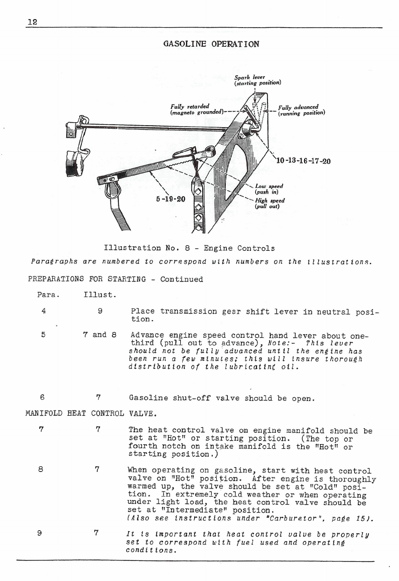
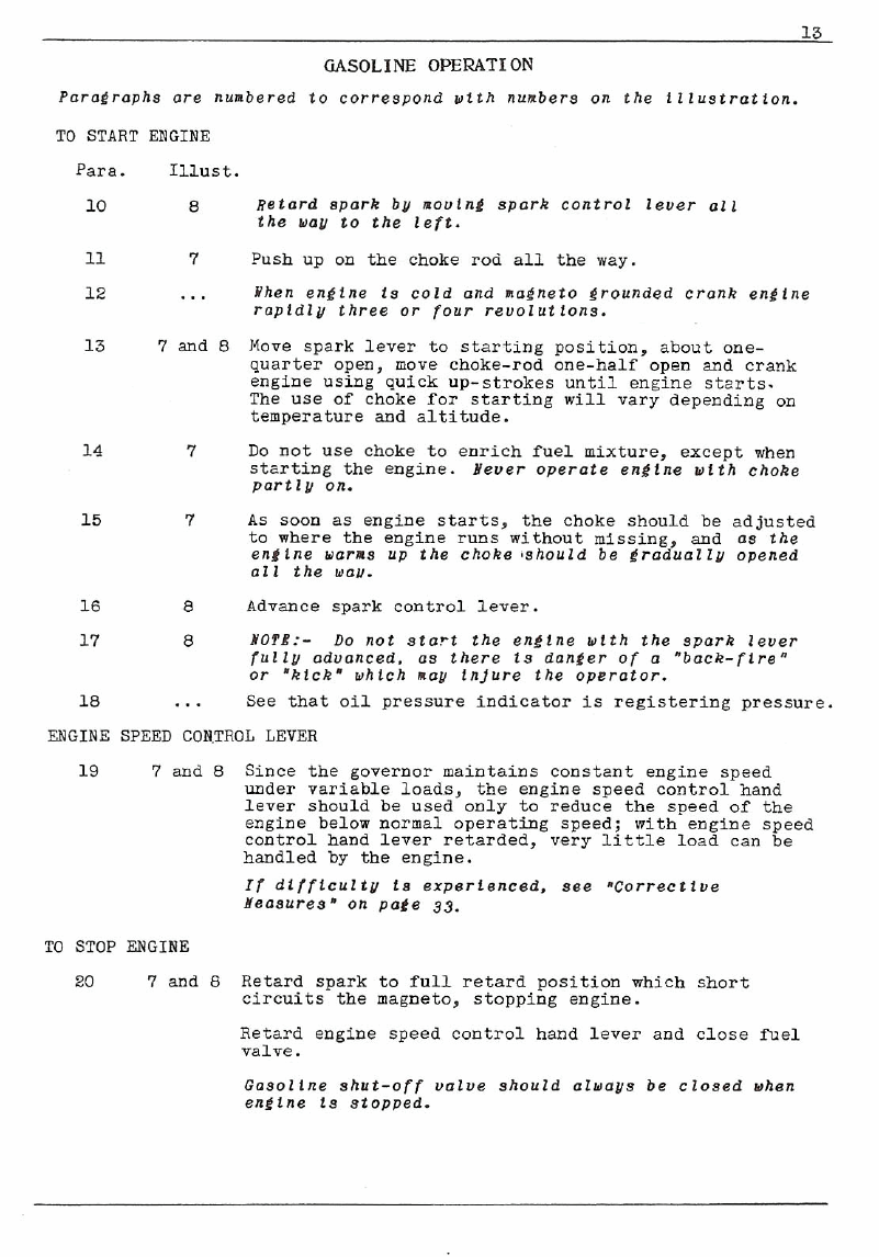
8
-
Engine Controls
Paragraphs are numbered to correspond with numbers on the illustrations.
PREPARATIONS FOR STAETING
-
Continued
Para. Illust.
4
9
Place transmission gezr shift lever in neutral posi-
tion.
5
7
and
8
Advance engine speed control hand lever about one-
third (pull out to advance),
Aiote:- This lever
should not be fully advanced until the engine has
been run a few minutes; this will insure thorough
distribution of the lubricating oil.
6
7
Gasoline shut-off valve should be open.
IW
IFOLD
HEAT
CONTROL
VALVE.
The heat control valve on engine manifold should
be
set at "Hotv or starting position. (The top or
fourth notch on intake manifold
is
the "Hot" or
starting position
.)
When operating on gzsoline, start with heat control
valve on "Hotu position. After engine
is
thoroughly
warmed up, the valve should be set at VoldUposi-
tion. In extremely cold weather or when operating
under light load, the heat control valve should
be
set at "Intermediaten position.
(Also see instructions under *Carburetor1', page
151.
It is important that heat control valve be properly
set to correspond wtth fuel used and operating
condit ions.
GASOLINE
OPERATION
PnroCrophs ore nunbered to correspond vtth nunbers
on
the lllustrotion.
TO
START ENGINE
Para.
10
11
12
13
8
Retard spark by novlnl spark control leuer 011
the
way
to the left.
7
Push up on the choke rod all the way.
...
When sngtne is cold
and
laeneto grounded cronk engine
roptdlu three or four revolutions.
7
and
8
Move spark lever to starting position, about one-
quarter open, move choke-rod ine-half.open and crank
engine using quick up-strokes until engine starts.
The use of choke for starting will varv deoendine
on
.
.
---.
---
temperature and altitude.
7
DO
not use choke to enrich fuel mixture, except when
starting the engine.
Uevsr
operote engtna with choke
partly
on.
7
As
soon as engine starts, the choke should be adjusted
to where the engine runs without missing, and
os the
enline raras up the choke ,should be eradually opened
011
the
wnu.
8
Advance spark control lever.
8
YO?#:-
Do
not start the engine wlth the spork lever
lullu aduanced.
os
there
ts
danger of
n
"back-firen
or
'kick' vhich sou injure the opcrotor.
...
See that ail pressure indicator
is
registering pressure.
ENGINE SPEED CONTROL LEVER
7
and
8
Since the governor maintains constant engine speed
under variable loads, the engine speed control hand
lever should be used only to reduce the speed of the
engine below normal operating speed; with engine speed
control hand lever retarded, very little load can
be
handled by the engine.
I1 dllftculty is experienced, see .Correcctue
aeosures" on pole
33.
TO
STOP ENGINE
20
7
and
8
Retard spark to full retard position which short
circuits the magneto, stopping engine.
Retard engine speed control hand lever and close fuel
valve.
Gasoline shut-off uolve should oluaus be closed when
eneine is stopped.

GASOLINE
OWRATION
Paraeraphs
ore
numbered to correspond aith numbers on
the
illustrations.
TO START TRACTOR
Para. Illust.
21
7
and
9
GEm
SHIFTING
24
9
Place left foot on clutch pedal and press down firmly,
holding in this position; this disengages the clutch.
Clutch must always be disengaged while shifting gears.
>%Ye gear shifting lever to desired speed.
Gently release pressure on clutch pedal; this engages
clutch and causes tractor.to move.
Do not drlve wlth
foot resting on clutch pedal.
Always disengage clutch before making a gear
shift.
N
-
Neutral
1st
-
Low
speed forward
2nd
-
Intermediate speed
forward
3rd
-
High speed forward
H
-
Reverse
Showing different posi-
tions of gear shifting lever.
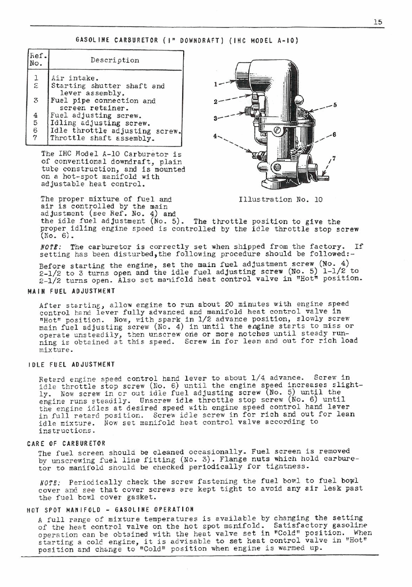
15
GASOLINE CARaURETOR
(I"
DOWNDRAFT) (IHC MODEL 1-10]
Description
Air
intake.
starting %utter shaft
and
I:
I
lever assembly.
Fuel Dim connection and
I
re
etin
I
Fuel adjusting screw.
Idling zdjusting
screw.
Idle throttle adjusting screw.
Throttle shaft Essembly.
The
IHC
Modeld-10 Carburetor
is
of conventional downdraft, plain
tute construction, and
is
mounted
an
a
hat-s~otmznifold with
ad justable- heat control.
Illustration
No.
10
The proper mixture of fuel
and
air
is controlled by the main
adjustment
(see
Ref.
No.
4)
and
the idle fuel adjustment
(No.
5). The throttle position to give the
proper idling engine speed
is
controlled by the idle throttle stop screw
(No.
6:.
NOTE:
The carburetor
is
correctly set when shipped from the factory.
If
setting has been disturbed,the following procedure should be fallowed:-
Before starting the engine, set the main fuel adjustment
screw
(No.
4)
2-1/2 to
3
turns open and tne idle fuel adjusting screw
(NO-
5) 1-1/2 to
2-l/2 turns open. Also set maqifold heat control valve in 'Hot" position.
After stbrtinc, allow ergine to
run
about 20 minutes with engine speed
conti-01
bznd
lever fully advanced
and
manifold heat control velve in
.Hot" position.
Now,
vith spark in l/2 advance position, slowly screw
main fuel adjusting screw
(ko.
4)
in
until the engine starts to
miss
or
operete unsteadily, then
unscrew
one
or
more
notches until steady run-
ning is obtcined at this speed. Screw in for lean and out
for
rich load
mixture.
IDLE FUEL ADJUSTMENT
Retzrd engine speed control hand lever to about 1/4 advance. Screw in
idle throttle stop
screw
(No.
6)
until the engine speed increzses slight-
ly.
Nor
screw
in
or
out idie fuel adjusting screw
(No.
5) until the
engine runs steadily. Unscrew idle throttle stop screw
(No.
6)
until
the engine idles at desired speed with engine speed control hand lever
in full retgrd 2osition. Screw idle screw in for rich and out for lean
idle mixture. Now set menifole heat control velve accorbing to
instrUCtionB.
CARE OF CARBURETOR
The fuel
screen
should
be
cleaned
occasionally.
Fuel sereen
is
removed
bv
unscrewing fuel line fitting (No.
3).
Flange nuts which hold carbure-
tbr
to manifold snould
be
checked periodically for tigntness.
NOTE:
Periodically check the screw fastening the fuel bow1 to fuel boy1
cover
an6
see
that
cover
screws
are
kept tight to avoid 2ny
sir
leak
past
the fuel bou;l cover gasket.
HOT SPOT MANIFOLD
-
GASOLINE DPERATION
A
full range
of
mixture temperatures
is
available by changing the setting
of the heat control valve on the hot spot msnifold. Satisfactory gasoline
operation
can
be
obtained with the heat valve set in "Cold' position. When
starting
s
~016engine,
it
is
advisable to set heat control valve in
"Hot"
position and chsnge to "Cold" position when engine
is
wzrmed up.

ENGINE SPEED CONTROL
LEVEfi
The lever on the left hand side of the fuel tank is the engine speed
control lever.
The rated or governed speed is 1650 R.P.M. for full load, which gives
a fast idling (no-load)
speed
of approximately
1800
R.P.M.
Inportant!
Por
all-round satlsfoctory operatlon. the engine should
not be ldlad down to
a
speed below
300
to
400
R.P.I.
GOVERNOR CONTROL ADJUSTEIENT
The governor is set at the factory and should require no adjustaent.
STEERING AND BRWLES
The brakes take hold when the front wheels are swung to the extreme
right or left, thus czusing either of the rear wheels to lock, and the
tractor to pivot in its course
of
travel. The question as to which
rear
wheel locks depends on the direction of steering; for exemple,
when front wheels are turned to left, the left rear wheel lacks and
tractor pivots
to
the left.
TO
STOP
TRACTOR
Disengage clutch by pressing down firmly on clutch pedal, then move
gear shifting lever to neutral position.
Use
the brakes if necessary.
SnFETY
FIRST:-
Stop power Coke-off before dismounting from tractor.
Be
sure gear shift lousr ts
1"
neutral posltlon before
dlsmountlng from tractor.
TO STOP ENOINE
See instructions for stopping engine:-
Distillate
operatlon
-
page
9.
G080line Operation
-
pole
13.
Rote: If adlustaent
of
the carburetor snould be neeesaory. follow
instructions iluen on pages
10
ond
15.
REAR
WHEELS
Cnntlon
-
dfter
a
neu troctor hos been run.0 short tine.
or
the rear
wheels hove been reamed or changed position, ttlhten the rear uheel
hub bolt nuts. See other Rear Yheel instructions on page
44.
Be sure expanding set screw (when used) is released when tightening
up on rear axle clamp bolts.
DRAW
BAR
.YARNING'
DO
not hitch to the troctor at
my
polnt except to the drav bor.
DO not ottenpt to pull vhen drav
bar
is rimved.
Draw bar and brace bolts nust be kept tleht
Alu~ysuse drow bar
and
braces.
tdtso
see
page
45
for
'Outek
Atlochable' drow
bnrl.

COLD WEATHER OPERATION
If
Tractor is to be operated when temperature is below
32O
F.
certain
protective precautions are necessary.
Use "Wintern engine and transmission lubricants.
(Sea
"Lubrtcatlon
Chart").
Use a good grade of engine oilhaving the proper body, with
a
loa
cold test, suitable for existing climatic conditions.
Use
kerosene in magneto coupling.
-
-
Transmission oil must be light enough to flow in prevailing atmosphere
temperature. If transmission lubricant available
is
too heavy dilute
sufficiently with lighter oil so
it
will
flow readily.
Failure of transmission lubricant to flaw readily
will
soon cause
bearings to be without oil.
ENGINE
STARTING
Have oil in engine crankcase light enough that engine
will
not be too
stiff to crank.
If
desired, during very cold weather, the engine oil in the crankcase
pan
can
be completely drained each night.
Do
this while the oil is
warm so
it
will
drain freely.
Before
refilling, warm ail thoroughly and pour into crankcase just
before starting the engine, as this
will
insure oil thin enough
to
pass through screen over pump suction, also preventing condensation of
moisture in crankcase pan.
Filling fuel tank at end
of
day's run wil1,prevent moisture from
collecting in the tank.
Use
a
high test winter grade
of
gasoline for starting.
If
engine has been idle far any length of time check crankcase pan,
fuel tank and fuel bawl for any ice formation before starting.
If
trouble is
experienced,
see
.Correclloe
Xeasures',
pale
33.
also
see
nogneto instructions
on
pot6
32.
Table of contents


