McCulloch MC19542LT User manual

www.mcculloch.biz
532 44 58-30 08.25.11 TH
Printed in the U.S.A.
• Assembly
• Operation
• Maintenance
• Service and Adjustments
• Storage
• Troubleshooting
OPERATOR’S MANUAL
MODEL NO. MC19542LT
19.5 HP
*
42 INCH
LAWN TRACTOR
*As rated by the engine manufacturer
Gasoline containing up to 10% ethanol (E10) is acceptable for use in this machine.
The use of any gasoline exceeding 10% ethanol (E10) will void the product warranty.
For Parts and Service, contact our authorized distributor:
call 1-800-849-1297 For Technical Assistance: call 1-800-829-5886
WARNING:
Read this Manual and follow all Warnings
and Safety Instructions. Failure to do so
can result in serious injury.

2
SAFETY RULES
Safe Operation Practices for Ride-On Mowers
DANGER: THIS CUTTING MACHINE IS CAPABLE OF AMPUTATING HANDS AND FEET AND THROWING OBJECTS. FAILURE
TO OBSERVE THE FOLLOWING SAFETY INSTRUCTIONS COULD RESULT IN SERIOUS INJURY OR DEATH.
• Never leave a running machine unattended. Always turn
off blades, set parking brake, stop engine, and remove
keys before dismounting.
• Disengage blades when not mowing. Shut off engine
and wait for all parts to come to a complete stop before
cleaning the machine, removing the grass catcher, or
unclogging the discharge chute.
• Operate machine only in daylight or good artificial light.
• Do not operate the machine while under the influence of
alcohol or drugs.
• Watchfortrafficwhenoperatingnearorcrossingroadways.
• Use extra care when loading or unloading the machine
into a trailer or truck.
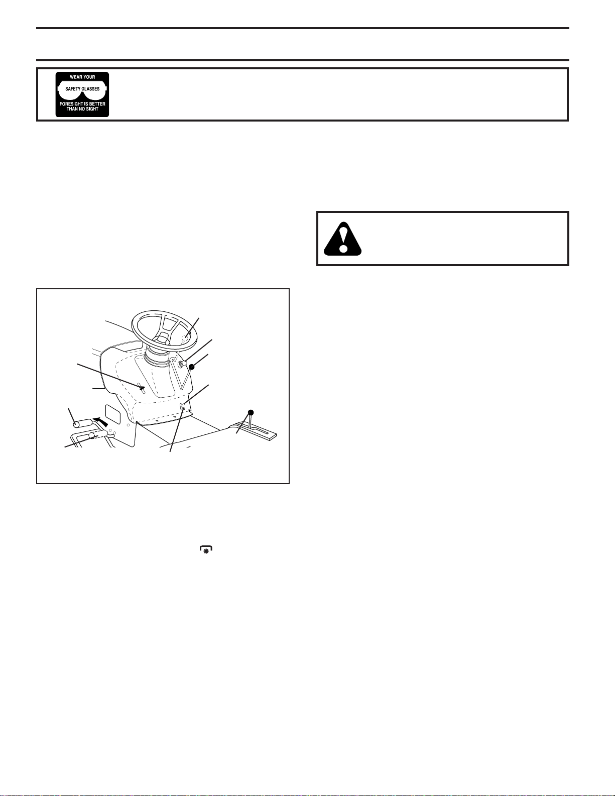
• Always wear eye protection when operating machine.
• Data indicates that operators, age 60 years and above,
areinvolvedinalargepercentageofridingmower-related
injuries. These operators should evaluate their ability to
operate the riding mower safely enough to protect them-
selves and others from serious injury.
• Follow the manufacturer's recommendation for wheel
weights or counterweights.
• Keepmachinefreeofgrass,leavesorotherdebrisbuild-up
which can touch hot exhaust / engine parts and burn. Do
not allow the mower deck to plow leaves or other debris
which can cause build-up to occur. Clean any oil or fuel
spillage before operating or storing the machine. Allow
machine to cool before storage.
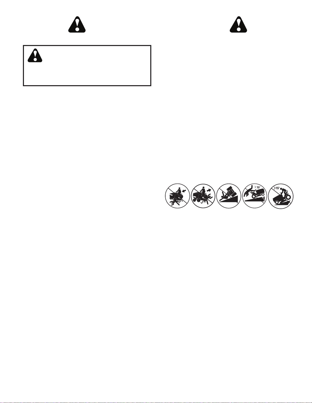
II. SLOPE OPERATION
Slopes are a major factor related to loss of control and tip-
over accidents, which can result in severe injury or death.
Operation on all slopes requires extra caution. If you cannot
back up the slope or if you feel uneasy on it, do not mow it.
• Mow up and down slopes, not across.
• Watch for holes, ruts, bumps, rocks, or other hidden ob-
jects. Uneven terrain could overturn the machine. Tall
grass can hide obstacles.
• Choose a low ground speed so that you will not have to
stop or shift while on the slope.
• Do not mow on wet grass. Tires may lose traction.
Alwayskeepthemachineingearwhengoingdownslopes.
Do not shift to neutral and coast downhill.
• Avoid starting, stopping, or turning on a slope. If the tires
lose traction, disengage the blades and proceed slowly
straight down the slope.
• Keep all movement on the slopes slow and gradual. Do
not make sudden changes in speed or direction, which
could cause the machine to roll over.
• Useextracarewhileoperatingmachinewithgrasscatch-
ers or other attachments; they can affect the stability of
the machine. Do no use on steep slopes.
• Do not try to stabilize the machine by putting your foot
on the ground.
• Do not mow near drop-offs, ditches, or embankments. The
machine could suddenly roll over if a wheel is over the edge
or if the edge caves in.
I. GENERAL OPERATION
• Read, understand, and follow all instructions on the ma-
chine and in the manual before starting.
• Do not put hands or feet near rotating parts or under the
machine.Keepclearofthedischargeopeningatalltimes.
• Only allow responsible adults, who are familiar with the
instructions, to operate the machine.
• Clear the area of objects such as rocks, toys, wire, etc.,
which could be picked up and thrown by the blades.
• Ensure the area is clear of bystanders before operating.
Stop machine if anyone enters the area.
• Never carry passengers.
• Do not mow in reverse unless absolutely necessary.
Always look down and behind before and while backing.
• Never direct discharged material toward anyone. Avoid
dischargingmaterialagainstawallorobstruction.Material
may ricochet back toward the operator. Stop the blades
when crossing gravel surfaces.
• Donotoperatemachinewithouttheentiregrasscatcher,dis-
chargechute,orothersafetydevicesinplaceandworking.
• Slow down before turning.
WARNING: In order to prevent accidental
starting when setting up, transporting,
adjustingormakingrepairs,alwaysdiscon-
nect spark plug wire and place wire where
it cannot contact spark plug.
WARNING
Engineexhaust,someofitsconstituents,andcertain
vehicle components contain or emit chemicals
known to the State of California to cause cancer
and birth defects or other reproductive harm.
WARNING
Battery posts, terminals and related accessories
containleadandleadcompounds,chemicalsknown
to the State of California to cause cancer and birth
defects or other reproductive harm. Wash hands
after handling.
WARNING:Donotcoastdownahillinneut-
ral, you may lose control of the tractor.
WARNING: Tow only the attachments that
are recommended by and comply with
specifications of the manufacturer of your
tractor. Use common sense when towing.
Operate only at the lowest possible speed
whenon a slope. Too heavyof a load,while
on a slope, is dangerous. Tires can lose
traction with the ground and cause you to
lose control of your tractor.

3
SAFETY RULES
Safe Operation Practices for Ride-On Mowers
• Ensure the area is clear of bystanders before operating.
Stop machine if anyone enters the area.
• Never carry passengers.
• Do not mow in reverse unless absolutely necessary.
Always look down and behind before and while backing.
• Never carry children, even with the blades shut off. They
may fall off and be seriously injured or interfere with safe
machine operation. Children who have been given rides
in the past may suddenly appear in the mowing area
for another ride and be run over or backed over by the
machine.
• Keep children out of the mowing area and in the watchful
care of a responsible adult other than the operator.
• Be alert and turn machine off if a child enters the area.
• Beforeandwhilebacking,lookbehindanddownforsmall
children.
• Mow up and down slopes (15° Max), not across.
• Choose a low ground speed so that you will not have to
stop or shift while on the slope.
• Avoid starting, stopping, or turning on a slope. If the tires
lose traction, disengage the blades and proceed slowly
straight down the slope.
• If machine stops while going uphill, disengage blades,
shift into reverse and back down slowly.
• Do not turn on slopes unless necessary, and then, turn
slowly and gradually downhill, if possible.
• When loading or unloading this machine, do not exceed
the maximum recommended operation angle of 15°.
III. CHILDREN
WARNING. CHILDRENCANBEINJUREDBY
THISEQUIPMENT. TheAmericanAcademy
ofPediatricsrecommendsthatchildrenbea
minimumof12yearofagebeforeoperating
a pedestrian controlled lawn mower and a
minimumof16yearsofagebeforeoperating
a riding lawn mower.
Tragic accidents can occur if the operator is not alert to the
presence of children. Children are often attracted to the ma-
chine and the mowing activity. Never assume that children
will remain where you last saw them.
• Keep children out of the mowing area and in the watchful
care of a responsible adult other than the operator.
• Be alert and turn machine off if a child enters the area.
• Beforeandwhilebacking,lookbehindanddownforsmall
children.
• Never carry children, even with the blades shut off. They
may fall off and be seriously injured or interfere with safe
machine operation. Children who have been given rides
in the past may suddenly appear in the mowing area for
anotherrideandberunoverorbackedoverbythemachine.
• Never allow children to operate the machine.
• Use extra care when approaching blind corners, shrubs,
trees,or other objects thatmayblockyour view of achild.
IV. TOWING
• Tow only with a machine that has a hitch designed for
towing.Donotattachtowedequipmentexceptatthehitch
point.
• Follow the manufacturer's recommendation for weight
limits for towed equipment and towing on slopes.
• Never allow children or others in or on towed equipment.
• Onslopes,the weightof thetowed equipmentmaycause
loss of traction and loss of control.
• Travel slowly and allow extra distance to stop.
V. SERVICE
SAFE HANDLING OF GASOLINE
To avoid personal injury or property damage, use extreme
care in handling gasoline. Gasoline is extremely flammable
and the vapors are explosive.
• Extinguishallcigarettes, cigars,pipes, andothersources
of ignition.
• Use only approved gasoline container.
• Neverremovegascaporaddfuelwiththeenginerunning.
Allow engine to cool before refueling.
• Never fuel the machine indoors.
• Never store the machine or fuel container where there
is an open flame, spark, or pilot light such as on a water
heater or other appliances.
• Never fill containers inside a vehicle or on a truck or
trailer bed with plastic liner. Always place containers on
the ground away from your vehicle when filling.
• Remove gas-powered equipment from the truck or trailer
and refuel it on the ground. If this is not possible, then
refuel such equipment with a portable container, rather
than from a gasoline dispenser nozzle.
• Keep the nozzle in contact with the rim of the fuel tank or
container opening at all times until fueling is complete.
Do not use a nozzle lock-open device.
• If fuel is spilled on clothing, change clothing immediately.
• Never overfill fuel tank. Replace gas cap and tighten
securely.
GENERAL SERVICE
• Never operate machine in a closed area.
• Keep all nuts and bolts tight to ensure the equipment is
in safe working condition.
• Never tamper with safety devices. Check their proper
operation regularly.
• Keepmachine freeofgrass,leaves,orotherdebrisbuild-
up. Cleanoilorfuel spillageand removeany fuel-soaked
debris. Allow machine to cool before storing.
• Ifyoustrikeaforeignobject,stopandinspectthemachine.
Repair, if necessary, before restarting.
• Never make any adjustments or repairs with the engine
running.
• Checkgrasscatchercomponentsandthedischargechute
frequentlyandreplacewithmanufacturer'srecommended
parts, when necessary.
• Mowerblades are sharp. Wraptheblade or weargloves,
and use extra caution when servicing them.
• Check brake operation frequently. Adjust and service as
required.
• Maintain or replace safety and instruction labels, as nec-
essary.

4
TABLE OF CONTENTS
SAFETY RULES.........................................................2-3
PRODUCT SPECIFICATIONS.......................................4
CUSTOMER RESPONSIBILITIES.................................4
ASSEMBLY.................................................................6-7
OPERATION .............................................................8-13
MAINTENANCE SCHEDULE......................................14
MAINTENANCE .....................................................14-17
SERVICE AND ADJUSTMENTS............................18-22
STORAGE....................................................................23
TROUBLESHOOTING............................................24-25
WARRANTY.................................................................28
PRODUCT SPECIFICATIONS
GASOLINE CAPACITY 1.50 GALLONS/5,67 L
AND TYPE: UNLEADED REGULAR
OIL TYPE (API: SG-SL): SAE 30 (above 32°F/0°C)
SAE5W-30(below32°F/0°C)
OIL CAPACITY: W/ FILTER: 56 Oz./1,65 L
W/O FILTER: 48 Oz./1,4 L
SPARK PLUG: CHAMPION RC12YC
(GAP: .030".76 mm)
GROUND SPEED Forward: 1st 1.0/1,6
(MPH/KPH): 2nd 1.4/2,3
3rd 2.1/3,4
4th 3.1/5,1
5th 4.0/6,4
6th 5.1/8,2
Reverse: 1.6/2,6
CHARGING SYSTEM: 3 AMPS BATTERY
5 AMPS HEADLIGHTS
BATTERY: AMP/HR: 28
MIN. CCA: 230
CASE SIZE: U1R
BLADE BOLT TORQUE: 45-55 FT. LBS. (62-75 Nm)
CONGRATULATIONS on yourpurchase ofa new tractor.
It has been designed, engineered and manufactured to
giveyou thebestpossibledependabilityandperformance.
Should you experience any problem you cannot easily
remedy, please contact your nearest authorized service
center/department. Wehavecompetent,well-trainedtechni-
cians and the proper tools to service or repair this tractor.
Please read and retain this manual. The instructions will
enableyoutoassembleandmaintainyourtractorproperly.
Always observe the “SAFETY RULES”.
CUSTOMER RESPONSIBILITIES
• Read and observe the safety rules.
• Follow a regular schedule in maintaining, caring for
and using your tractor.
• Followtheinstructionsunder“Maintenance”and“Stor-
age” sections of this manual.
• Wear proper Personal Protective Equipment (PPE)
whileoperatingthismachine,including(ataminimum)
sturdyfootwear,eyeprotection,andhearingprotection.
Do not mow in shorts and/or, open toed footwear.
• Always let someone know you are outside mowing.
WARNING: This tractor is equipped with an internal com-
bustion engine and should not be used on or near any un-
improvedforest-covered,brush-coveredorgrass-covered
land unless the engine’s exhaust system is equipped with
a spark arrester meeting applicable local or state laws (if
any). If a spark arrester is used, it should be maintained
in effective working order by the operator.
A spark arrester for the muffler is available through your
nearest authorized service center/department.
In the state of California the above is required by law
(Section 4442 of the California Public Resources Code).
Other states may have similar laws. Federal laws apply
on federal lands.

5
Steering Wheel
(1) Washer
(1) Knob
Steering
Wheel Insert
Seat
(1) Seat
Steering
Boot
Steering
Extension
Shaft
Steering Wheel
Adapter
Keys
(2) Keys
Slope Sheet
(1) Hex Bolt
5/16-18 x 4 (1) 5/16 Lock Washer
(1) Large Flat Washer
UNASSEMBLED PARTS

6
ASSEMBLY
Your new tractor has been assembled at the factory with exception of those parts left unassembled for shipping purposes.
To ensure safe and proper operation of your tractor all parts and hardware you assemble must be tightened securely. Use
the correct tools as necessary to insure proper tightness.
Fig. 2
TOOLS REQUIRED FOR ASSEMBLY
A socket wrench set will make assembly easier. Standard
wrench sizes are listed.
(1) 5/16" wrench Utility knife
(2) 7/16" wrenches Tire pressure gauge
(2) 1/2" wrenches Pliers
(1) 9/16" wrench
Whenrightorlefthandismentionedinthismanual,itmeans
when you are in the operating position (seated behind the
steering wheel).
INSTALL SEAT (See Fig. 3)
Adjust seat before tightening adjustment knob.
• Remove adjustment knob and flat washer securing
seat to cardboard packing and set aside for assembly
of seat to tractor.
• Pivotseatupwardandremovefromthecardboardpack-
ing. Remove the cardboard packing and discard.
TO CHECK BATTERY (See Fig. 1)
• Lift seat to raised position.
NOTE: If this battery is put into service after month and
yearindicatedonlabel(labelislocatedbetweenterminals)
charge battery for minimum of one hour at 6-10 amps.
(See "BATTERY" in Maintenance section of this manual
for charging instructions).
• For battery and battery cable installation see "RE-
PLACINGBATTERY"inthe"ServiceandAdjustments"
section in this manual.
02602
SEAT LABEL
Fig. 1
TOREMOVETRACTORFROMCARTON
UNPACK CARTON
• Remove all accessible loose parts and parts cartons
from carton .
• Cut along dotted lines on all four panels of carton.
Remove end panels and lay side panels flat.
• Check for any additional loose parts or cartons and
remove.
BEFOREREMOVINGTRACTOR FROM
SKID
TO INSTALL STEERING WHEEL (See Fig. 2)
ASSEMBLE EXTENSION SHAFT AND BOOT
• Slide extension shaft onto lower steering shaft.
• Place tabs of steering boot over tab slots in dash and
push down to secure.
INSTALL STEERING WHEEL
• Positionfrontwheelsofthe tractor so they are pointing
straight forward.
• Remove steering wheel adapter from steering wheel
and slide adapter onto steering shaft extension.
• Position steering wheel so cross bars are horizontal
(left to right) and slide inside boot and onto adapter.
• Assemble large flat washer, lock washer, hex bolt and
tighten securely.
• Snap steering wheel insert into center of steering
wheel.
• Remove protective materials from tractor hood and
grill.
IMPORTANT: CHECK FOR AND REMOVE ANY STAPLES IN
SKIDTHATMAY PUNCTURETIRES WHERETRACTOR ISTO
ROLL OFF SKID.
02819
LOWER
STEERING
SHAFT
STEERING
BOOT
EXTENSION
SHAFT
STEERING
WHEEL
INSERT
ADAPTER
BOLT
LARGE FLAT
WASHER
LOCK
WASHER

7
ASSEMBLY
Fig. 3
00835
SEAT PAN
SHOULDER
BOLT
ADJUSTMENT
KNOB
FLAT WASHER
SEAT
NOTE:Youmaynowrollyourtractorofftheskid.Followthe
instructions below to remove the tractor from the skid.
WARNING:Beforestarting,read,understandandfollow
all instructions in the Operation section of this manual. Be
sure tractor is in a well-ventilated area. Be sure the area in
front of tractor is clear of other people and objects.
TOROLLTRACTOROFFSKID (SeeOperation
section for location and function of controls)
• Raise attachment lift lever to its highest position.
• Releaseparkingbrakebydepressingclutch/brakepedal.
• Place gearshift lever in neutral (N) position.
• Roll tractor forward off skid.
• Removebandingholdingthedeflectorshieldupagainst
tractor.
Continue with the instructions that follow.
CHECK TIRE PRESSURE
The tires on your tractor were overinflated at the factory
for shipping purposes. Correct tire pressure is important
for best cutting performance.
• Reduce tire pressure to PSI shown on tires.
✓CHECKLIST
BEFORE YOU OPERATE YOUR NEW TRACTOR, WE
WISHTOASSURETHATYOURECEIVETHEBESTPER-
FORMANCEANDSATISFACTIONFROMTHISQUALITY
PRODUCT.
PLEASE REVIEW THE FOLLOWING CHECKLIST:
✓All assembly instructions have been completed.
✓No remaining loose parts in carton.
✓Battery is properly prepared and charged. (Minimum
1 hour at 6 amps).
✓Seat is adjusted comfortably and tightened securely.
✓All tires are properly inflated. (For shipping purposes,
the tires were overinflated at the factory).
✓Be sure mower deck is properly leveled side-to-side/
front-to-rear for best cutting results. (Tires must be
properly inflated for leveling).
✓Checkmoweranddrivebelts. Besurethey are routed
properly around pulleys and inside all belt keepers.
✓Check wiring. See that all connections are still secure
and wires are properly clamped.
WHILELEARNINGHOWTOUSEYOURTRACTOR,PAY
EXTRA ATTENTION TO THE FOLLOWING IMPORTANT
ITEMS:
✓Engine oil is at proper level.
✓Fuel tank is filled with fresh, clean, regular unleaded
gasoline.
✓Become familiar with all controls, their location and
function. Operate them before you start the engine.
✓Be sure brake system is in safe operating condition.
✓ Be sure Operator Presence System and Reverse Op-
eration System (ROS) are working properly (See the
Operation and Maintenance sections in this manual).
• Place seat on seat pan and assemble shoulder bolt.
Tighten shoulder bolt securely.
• Assemble adjustment knob and flat washer loosely.
Do not tighten.
• Lower seat into operating position and sit on seat.
• Slideseatuntilacomfortablepositionisreachedwhich
allows you to press clutch/brake pedal all the way
down.
• Get off seat without moving its adjusted position.
• Raise seat and tighten adjustment knob securely.
CHECK DECK LEVELNESS
For best cutting results, mower housing should be prop-
erly leveled. See “TO LEVEL MOWER HOUSING” in the
Service and Adjustments section of this manual.
CHECK FOR PROPER POSITION OF ALL
BELTS
See the figures that are shown for replacing motion and
mower blade drive belts in the Service and Adjustments
section of this manual. Verify that the belts are routed
correctly.
CHECK BRAKE SYSTEM
Afteryoulearnhowtooperateyourtractor,checktoseethat
thebrake is operatingproperly. See“TO CHECK BRAKE”
in the Service and Adjustments section of this manual.

8
OPERATION
These symbols may appear on your tractor or in literature supplied with the product. Learn and understand their mean-
ing.
DANGER, KEEP HANDS
AND FEET AWAY
FREE WHEEL
(Automatic Models only)
OVER TEMP
LIGHT
KEEP AREA CLEAR SLOPE HAZARDS
15
15
(SEE SAFETY RULES SECTION)
BATTERY REVERSE FORWARD
FAST SLOW
ENGINE ON
ENGINE OFF
OIL PRESSURE
FUEL
CHOKE
MOWER HEIGHT
PARKING BRAKE
LOCKED
PARKING BRAKE
UNLOCKED
REVERSE NEUTRAL HIGH LOW
ATTACHMENT
CLUTCH ENGAGED
PARKING BRAKE
IGNITION SWITCH
ATTACHMENT
CLUTCH DISENGAGED
P
ENGINE START
MOWER LIFT
Failure to follow instructions
could result in serious injury or
death. The safety alert symbol
is used to identify safety inform-
ation about hazards which can
result in death, serious injury
and/or property damage.
DANGER indicates a hazard which, if not avoided,
will result in death or serious injury.
WARNING indicates a hazard which, if not avoided,
could result in death or serious injury.
CAUTION indicates a hazard which, if not avoided,
might result in minor or moderate injury.
CAUTION when used without the alert symbol,
indicates a situation that could result in damage
to the tractor and/or engine.
FIRE indicates a hazard which, if not avoided,
could result in death, serious injury and/or
property damage.
HOT SURFACES indicates a hazard which,
if not avoided, could result in death, serious injury
and/or property damage.
REVERSE
OPERATION
SYSTEM (ROS)
LIGHTS ON
BRAKE/CLUTCH
PEDAL

9
OPERATION
KNOW YOUR TRACTOR
READTHISOPERATOR'SMANUALANDSAFETYRULESBEFOREOPERATINGYOURTRACTOR
Compare the illustrations with your tractor to familiarize yourself with the locations of various controls and adjustments.
Save this manual for future reference.
ATTACHMENT CLUTCH LEVER - Used to engage the
mower blades, or other attachments mounted to your
tractor.
ATTACHMENT LIFT LEVER - Used to raise, lower, and
adjust the mower deck or other attachments mounted to
your tractor.
CLUTCH/BRAKEPEDAL-Usedfordeclutchingandbrak-
ing the tractor and starting the engine.
GEARSHIFT LEVER - Selects the speed and direction
of the tractor.
IGNITION SWITCH - Used for starting and stopping the
engine.
Our tractors conform to the safety standards of the American National Standards Institute.
Fig. 4
02829
PARKING
BRAKE
CLUTCH/BRAKE
PEDAL
THROTTLE/CHOKE
CONTROL
GEAR SHIFT
LEVER
ATTACHMENT
LIFT LEVER
LIFT LEVER
PLUNGER
IGNITION
SWITCH
ATTACHMENT
CLUTCH LEVER
ROS "ON"
POSITION
HEIGHT
ADJUSTMENT
INDICATOR
LIGHT SWITCH
LIFT LEVER PLUNGER - Used to release attachment lift
lever when changing its position.
LIGHT SWITCH - Turns the headlights on and off.
PARKING BRAKE - Locks clutch/brake pedal into the
brake position.
REVERSE OPERATION SYSTEM (ROS) “ON” POSI-
TION - Allows operation of mower deck or other powered
attachment while in reverse.
THROTTLE/CHOKE CONTROL - Used for starting and
controlling engine speed.

10
OPERATION
PARKING BRAKE
"DISENGAGED"
POSITION
Fig. 5
CLUTCH/BRAKE
PEDAL "DRIVE"
POSITION
ATTACHMENT CLUTCH
LEVER "ENGAGED"
POSITION
IGNITION KEY
"DISENGAGED"
POSITION
PARKING BRAKE
"ENGAGED"
POSITION
GEAR SHIFT
LEVER
THROTTLE/
CHOKE
CONTROL
LEVER
"BRAKE"
POSITION
TO USE THROTTLE CONTROL (See Fig. 5)
Always operate engine at full throttle.
• Operating engine at less than full throttle reduces the
battery charging rate.
• Full throttle offers the best bagging and mower perfor-
mance.
TO MOVE FORWARD AND BACKWARD
(See Fig. 5)
The direction and speed of movement is controlled by the
gearshift lever.
• Start tractor with clutch/brake pedal depressed and
gearshift lever in neutral (N) position.
• Move gearshift lever to desired position.
• Slowly release clutch/brake pedal to start move-
ment.
IMPORTANT: BRING TRACTOR TO A COMPLETE STOP
BEFORE SHIFTING OR CHANGING GEARS. FAILURE
TO DO SO WILL SHORTEN THE USEFUL LIFE OF YOUR
TRANSAXLE.
TO ADJUST MOWER CUTTING HEIGHT
(See Fig. 7)
The position of the attachment lift lever determines the
cutting height.
• Grasp lift lever.
• Press plunger with thumb and move lever to desired
position.
The cutting height range is approximately 1-1/2 to 4".
The heights are measured from the ground to the blade tip
withtheenginenotrunning. Theseheightsareapproximate
and may vary depending upon soil conditions, height of
grass and types of grass being mowed.
• The average lawn should be cut to approximately
2-1/2"duringthecoolseason and to over 3"during hot
months. For healthier and better looking lawns, mow
often and after moderate growth.
• For best cutting performance, grass over 6" in height
should be mowed twice. Make the first cut relatively
high; the second to desired height.
HOW TO USE YOUR TRACTOR
TO SET PARKING BRAKE (See Fig. 5)
Your tractor is equipped with an operator presence sens-
ing switch. When engine is running, any attempt by the
operator to leave the seat without first setting the parking
brake will shut off the engine.
• Depress clutch/brake pedal into full “BRAKE” position
and hold.
• Placeparkingbrakeleverin“ENGAGED”positionand
releasepressurefromclutch/brakepedal. Pedalshould
remainin“BRAKE”position. Make sure parking brake
will hold tractor secure.
STOPPING (See Fig. 5)
MOWER BLADES -
• Tostopmowerblades,placeattachmentclutchcontrol
in the “DISENGAGED” position ( ).
GROUND DRIVE -
• To stop ground drive, depress clutch/brake pedal into
full “BRAKE” position.
• Move gearshift lever to neutral position.
ENGINE -
• Movethrottle control betweenhalfandfullspeed(fast)
position.
NOTE:Failuretomovethrottlecontrolbetweenhalfandfull
speed (fast) position, before stopping may cause engine
to “backfire”.
• Turn ignition key to “STOP” position and remove key.
Always remove key when leaving tractor to prevent
unauthorized use.
• Never use the choke to stop the engine.
IMPORTANT: LEAVING THE IGNITION SWITCH IN ANY
POSITIONOTHERTHAN"STOP"WILLCAUSETHEBATTERY
TO BE DISCHARGED, (DEAD).
NOTE: Under certain conditions when tractor is standing
idlewiththeenginerunning,hotengineexhaustgasesmay
cause “browning” of grass. To eliminate this possibility, al-
ways stop engine when stopping tractor on grass areas.
CAUTION: Always stop tractor com-
pletely,asdescribedabove,beforeleav-
ing the operator's position; to empty
grass catcher, etc.
The operation of any tractor can result in foreign objects thrown into the eyes, which can
result in severe eye damage. Always wear safety glasses or eye shields while operating
your tractor or performing any adjustments or repairs. We recommend standard safety
glasses or a wide vision safety mask worn over spectacles.

11
TO OPERATE ON HILLS
WARNING: Do not drive up or down
hills with slopes greater than 15° and
do not drive across any slope.
• Choose the slowest speed before starting up or down
hills.
• Avoid stopping or changing speed on hills.
• If slowing is necessary, move throttle control lever to
slower position.
• If stopping is absolutely necessary, push clutch/brake
pedal quickly to brake position and engage parking
brake.
• Move gearshift lever to 1st gear. Be sure you have
allowed room for tractor to roll slightly as you restart
movement.
• Torestartmovement,slowlyreleaseparkingbrakeand
clutch/brake pedal.
• Make all turns slowly.
OPERATION
Fig. 7
ATTACHMENT
CLUTCH LEVER
"DISENGAGED"
POSITION
ATTACHMENT
LIFT LEVER
HIGH POSITION
"ENGAGED" POSITION
LOW
POSITION
DEFLECTOR
SHIELD
REVERSE OPERATION SYSTEM (ROS)
Your tractor is equipped with a Reverse Operation System
(ROS).Any attempt bythe operator totravel in thereverse
direction with the attachment clutch engaged will shut off
the engine unless ignition key is placed in the ROS "ON"
position.
WARNING: Backing up with the attachment clutch en-
gaged while mowing is strongly discouraged. Turning the
ROS "ON", to allow reverse operation with the attachment
clutch engaged, should only be done when the operator
decides it is necessary to reposition the machine with the
attachment engaged. Do not mow in reverse unless
absolutely necessary.
USINGTHEREVERSEOPERATIONSYSTEM(SeeFig.6)
Only use if you are certain no children or other bystanders
will enter the mowing area.
• Depressclutch/brakepedalallthewaydownandhold.
• Withenginerunning,turnignitionkeycounterclockwise
to ROS "ON" position.
• Look down and behind before backing.
• Movegearshiftlevertoreverse(R)positionandslowly
release clutch/brake pedal to start movement.
• When use of the ROS is no longer needed, turn the
ignition key clockwise to engine "ON" position.
ROS "ON"
POSITION ENGINE "ON" POSITION
(NORMAL OPERATING)
0
2
8
2
8
Fig. 6
TO OPERATE MOWER (See Fig. 7)
Your tractor is equipped with an operator presence sens-
ing switch. Any attempt by the operator to leave the seat
withtheenginerunningandtheattachmentclutchengaged
willshut off the engine.You must remainfullyand centrally
positionedin the seattopreventtheengine from hesitating
or cutting off when operating your equipment on rough,
rolling terrain or hills.
• Select desired height of cut.
• Start mower blades by engaging attachment clutch
control.
TO STOP MOWER BLADES (See Fig. 7)
Disengage attachment clutch control.
CAUTION:Donotoperatethemowerwithout
eithertheentiregrasscatcher,onmowersso
equipped, or the deflector shield in place.
TO TRANSPORT
• Raiseattachmentlifttohighestpositionwithattachment
lift control.
• Whenpushingortowingyourtractor,besuregearshift
lever is in neutral (N) position.
• Do not push or tow tractor at more than five (5) MPH.
NOTE: To protect hood from damage when transporting
your tractor on a truck or a trailer, be sure hood is closed
and secured to tractor. Use an appropriate means of tying
hood to tractor (rope, cord, etc.).
TOWINGCARTSANDOTHERATTACHMENTS
Tow only the attachments that are recommended by and
complywithspecificationsofthemanufacturerofyourtrac-
tor. Use common sense when towing. Too heavy of a load,
while on a slope, is dangerous. Tires can lose traction with
the ground and cause you to lose control of your tractor.

12
OPERATION
BEFORE STARTING THE ENGINE
CHECK ENGINE OIL LEVEL
The engine in your tractor has been shipped, from the
factory, already filled with summer weight oil.
• Check engine oil with tractor on level ground.
• Removeoilfillcap/dipstickandwipeclean,reinsertthe
dipstick and screw cap tight, wait for a few seconds,
remove and read oil level. If necessary, add oil until
“FULL” mark on dipstick is reached. Do not overfill.
• For cold weather operation you should change oil for
easier starting (See “OIL VISCOSITY CHART” in the
Maintenance section of this manual).
• To change engine oil, see the Maintenance section in
this manual.
TO START ENGINE (See Fig. 4)
When starting the engine for the first time or if the engine
has run out of fuel, it will take extra cranking time to move
fuel from the tank to the engine.
• Sit on seat in operating position, depress clutch/brake
pedal and set parking brake.
• Place gear shift lever in neutral position.
• Move attachment clutch to “DISENGAGED” position.
• Move throttle control to choke position.
NOTE: Before starting, read the warm and cold starting
procedures below.
• Insertkeyintoignitionandturnkeyclockwiseto“START”
position and release key as soon as engine starts.
Do not run starter continuously for more than fifteen
seconds per minute. If the engine does not start after
severalattempts,movethrottlecontroltofastposition,
wait a few minutes and try again. If engine still does
not start, move the throttle control back to the choke
position and retry.
WARM WEATHER STARTING (50°F/10°C and above)
• When engine starts, move the throttle control to the
fast position.
• Theattachments andgrounddrivecan nowbeused.If
theenginedoesnotaccepttheload,restarttheengine
andallow it towarm up for oneminute using thechoke
as described above.
COLD WEATHER STARTING (50°F/10°C and below)
• When engine starts, allow engine to run with the
throttle control in the choke position until the engine
runs roughly, then move throttle control to fast posi-
tion. This may require an engine warm-up period from
severalseconds to several minutes,depending on the
temperature.
• The attachments can also be used during the engine
warm-up period.
NOTE: If at a high altitude (above 3000 feet) or in cold
temperatures(below32°F/0°C)thecarburetorfuelmixture
mayneedtobeadjustedforbestengineperformance.See
“TO ADJUST CARBURETOR” in the Service and Adjust-
ments section of this manual.
ADD GASOLINE
• Fill fuel tank to bottom of filler neck. Do not overfill.
Use fresh, clean, regular unleaded gasoline with a
minimum of 87 octane. (Use of leaded gasoline will
increase carbon and lead oxide deposits and reduce
valve life). Do not mix oil with gasoline. Purchase fuel
in quantities that can be used within 30 days to assure
fuel freshness.
CAUTION: Wipe off any spilled oil or
fuel. Donot store, spill or use gasoline
near an open flame.
IMPORTANT: WHENOPERATINGINTEMPERATURESBELOW
32°F (0°C), USE FRESH, CLEAN WINTER GRADE GASOLINE
TO HELP ENSURE GOOD COLD WEATHER STARTING.
CAUTION: Alcoholblendedfuels(calledgasohol
or using ethanol or methanol) can attract mois-
ture which leads to separation and formation of
acids during storage. Acidic gas can damage
thefuel system ofanengine while instorage. To
avoid engine problems, the fuel system should
be emptied before storage of 30 days or longer.
Drain the gas tank, start the engine and let it run
untilthefuellinesandcarburetorareempty. Use
freshfuelnextseason. SeeStorageInstructions
for additional information. Never use engine or
carburetor cleaner products in the fuel tank or
permanent damage may occur.

13
Fig. 8
OPERATION
MOWING TIPS
• Tire chains cannot be used when the mower housing
is attached to tractor.
• Mower should be properly leveled for best mowing
performance. See “TO LEVEL MOWER HOUSING”
intheServiceand Adjustments section of thismanual.
• Thelefthandsideofmowershouldbeusedfortrimming.
• Drive so that clippings are discharged onto the area
that has been cut. Have the cut area to the right of
the tractor. This will result in a more even distribution
of clippings and more uniform cutting.
• When mowing large areas, start by turning to the right
so that clippings will discharge away from shrubs,
fences, driveways, etc. After one or two rounds, mow
in the opposite direction making left hand turns until
finished (See Fig. 8).
• If grass is extremely tall, it should be mowed twice to
reduce load and possible fire hazard from dried clip-
pings. Make first cut relatively high; the second to the
desired height.
• Do not mow grass when it is wet. Wet grass will plug
mower and leave undesirable clumps. Allow grass to
dry before mowing.
• Always operate engine at full throttle when mow-
ing to assure better mowing performance and proper
discharge of material. Regulate ground speed by
selecting a low enough gear to give the mower cutting
performance as well as the quality of cut desired.
• When operating attachments, select a ground speed
that will suit the terrain and give best performance of
the attachment being used.

14
MAINTENANCE
LUBRICATION CHART
SPINDLE ZERK
FRONT WHEEL
BEARING ZERK
SAE 30 OR 10W30 MOTOR OIL
GENERAL PURPOSE GREASE
REFER TO MAINTENANCE “ENGINE” SECTION
IMPORTANT: DO NOT OIL OR GREASE THE PIVOT POINTS WHICH
HAVE SPECIAL NYLON BEARINGS. VISCOUS LUBRICANTS WILL
ATTRACT DUST AND DIRT THAT WILL SHORTEN THE LIFE OF
THE SELF-LUBRICATING BEARINGS. IF YOU FEEL THEY MUST
BE LUBRICATED, USE ONLY A DRY, POWDERED GRAPHITE TYPE
LUBRICANT SPARINGLY.
SPINDLE ZERK
FRONT WHEEL
BEARING ZERK
ENGINE
GEARSHIFT
PIVOTS
GENERAL RECOMMENDATIONS
Thewarranty onthistractordoes notcoveritemsthat have
beensubjectedtooperatorabuseornegligence. Toreceive
fullvaluefromthewarranty,operator must maintaintractor
as instructed in this manual.
Some adjustments will need to be made periodically to
properly maintain your tractor.
At least once a season, check to see if you should make
any of the adjustments described in the Service and
Adjustments section of this manual.
• At least once a year you should replace the spark plug,
clean or replace air filter, and check blades and belts
for wear. A new spark plug and clean air filter assure
proper air-fuel mixture and help your engine run better
and last longer.
BEFORE EACH USE
• Check engine oil level.
• Check brake operation.
• Check tire pressure.
• Check operator presence and
ROS systems for proper operation.
• Check for loose fasteners.
T
R
A
C
T
0
R
1 - Change more often when operating under a heavy load or in high ambient temperatures.
2 - Service more often when operating in dirty or dusty conditions.
E
N
G
I
N
E
3
2
2
2
2
3 - Replace blades more often when mowing in sandy soil.
4 - Not required if equipped with maintenance-free battery.
1
,
1,2
2
4
1,2
BEFORE
EACH
USE
EVERY
8
HOURS
EVERY
25
HOURS
EVERY
50
HOURS
EVERY
100
HOURS
EVERY
SEASON
BEFORE
STORAGE
Inspect Muffler/Spark Arrester
Clean Air Filter
Change Engine Oil (with oil filter)
Replace Air Filter Paper Cartridge
Replace Spark Plug
Check Engine Oil Level
Clean Engine Cooling Fins
Clean Air Screen
Replace Oil Filter (If equipped)
Replace Fuel Filter
Change Engine Oil (without oil filter)
Lubrication Chart
Check Brake Operation
Check Battery Level
Check Tire Pressure
Clean Battery and Terminals
MAINTENANCE
SCHEDULE
Check for Loose Fasteners
Check/Replace Mower Blades
Check Transaxle Cooling
Che
Check Operator Presence & ROS Systems
ck V-Belts
Check Mower Levelness

15
MAINTENANCE
TRACTOR
Always observe safety rules when performing any
maintenance.
BRAKE OPERATION
If tractor requires more than five (5) feet to stop at highest
speed in highest gear on a level, dry concrete or paved
surface, then brake must be checked and adjusted. (See
“TO CHECK BRAKE” in the Service and Adjustments
section of this manual).
TIRES
• Maintain proper air pressure in all tires (See the sides
of tires for proper PSI).
• Keep tires free of gasoline, oil, or insect control
chemicals which can harm rubber.
• Avoid stumps, stones, deep ruts, sharp objects and
other hazards that may cause tire damage.
NOTE: To seal tire punctures and prevent flat tires due
to slow leaks, tire sealant may be purchased from your
local parts dealer. Tire sealant also prevents tire dry rot
and corrosion.
OPERATOR PRESENCE SYSTEM AND REVERSE
OPERATION SYSTEM (ROS) (See Fig. 9)
Besure operator presenceandreverseoperationsystems
are working properly. If your tractor does not function as
described, repair the problem immediately.
• The engine should not start unless the brake pedal is
fully depressed, and the attachment clutch control is
in the disengaged position.
CHECK OPERATOR PRESENCE SYSTEM
• Whentheengineisrunning,anyattemptbytheoperator
to leave the seat without first setting the parking brake
should shut off the engine.
• When the engine is running and the attachment clutch
is engaged, any attempt by the operator to leave the
seat should shut off the engine.
• The attachment clutch should never operate unless
the operator is in the seat.
CHECK REVERSE OPERATION (ROS) SYSTEM
• When the engine is running with the ignition switch in
the engine "ON" position and the attachment clutch
engaged, any attempt by the operator to shift into
reverse should shut off the engine.
• When the engine is running with the ignition switch
in the ROS "ON" position and the attachment clutch
engaged, any attempt by the operator to shift into
reverse should NOT shut off the engine.
BLADE CARE
Forbestresultsmowerbladesmustbekeptsharp. Replace
bent or damaged blades.
CAUTION:Useonlyareplacementbladeap-
provedbythemanufacturerofyourtractor.
Using a blade not approved by the manu-
facturerofyourtractorishazardous,could
damageyourtractorandvoidyourwarranty.
BATTERY
Yourtractorhasabatterychargingsystemwhichissufficient
for normal use. However, periodic charging of the battery
with an automotive charger will extend its life.
• Keep battery and terminals clean.
• Keep battery bolts tight.
• Keep small vent holes open.
• Recharge at 6-10 amperes for 1 hour.
NOTE:Theoriginalequipmentbatteryonyourtractorismain-
tenancefree.Donotattempttoopenorremovecapsorcov-
ers.Addingorcheckinglevelofelectrolyteisnotnecessary.
TO CLEAN BATTERY AND TERMINALS
Corrosion and dirt on the battery and terminals can cause
the battery to “leak” power.
• Disconnect BLACK battery cable first then RED bat-
tery cable and remove battery from tractor.
• Rinse the battery with plain water and dry.
• Cleanterminalsandbatterycableendswithwirebrush
until bright.
• Coat terminals with grease or petroleum jelly.
• Reinstallbattery(See“REPLACING BATTERY" inthe
Service and Adjustments section of this manual).
Fig. 9
BLADE REMOVAL (See Fig. 10)
• Raise mower to highest position to allow access to
blades.
NOTE: Protect your hands with gloves and/or wrap blade
with heavy cloth.
• Remove blade bolt by turning counterclockwise.
• Install new or resharpened blade with stamped "THIS
SIDE UP" facing deck and mandrel assembly.
IMPORTANT: TO ENSURE PROPER ASSEMBLY, CENTER
HOLE IN BLADE MUST ALIGN WITH STAR ON MANDREL
ASSEMBLY.
• Install and tighten blade bolt securely (45-55 Ft. Lbs.
torque/62-75 Nm).
IMPORTANT: SPECIAL BLADE BOLT HEAT TREATED.
Fig. 10
ROS "ON"
POSITION ENGINE "ON" POSITION
(NORMAL OPERATING)
0
2
8
2
8
BLADE
BLADE BOLT
(SPECIAL)
CENTER HOLE
STAR
MANDREL ASSEMBLY

16
MAINTENANCE
Fig. 11
ENGINE
LUBRICATION
Only use high quality detergent oil rated with API service
classification SG-SL. Select the oil’s SAE viscosity grade
according to your expected operating temperature.
NOTE: Although multi-viscosity oils (5W30, 10W30 etc.)
improvestartingincoldweather,theywillresultinincreased
oil consumption when used above 32°F/0°C. Check your
engine oil level more frequently to avoid possible engine
damage from running low on oil.
Change the oil after every 50 hours of operation or at least
onceayearifthetractorisnotusedfor50hoursinoneyear.
Check the crankcase oil level before starting the engine
and after each eight (8) hours of operation. Tighten oil fill
cap/dipstick securely each time you check the oil level.
TEMPERATURE RANGE ANTICIPATED BEFORE NEXT OIL CHANGE
SAE VISCOSITY GRADES
-20 0 30 40 80 100
-30 -20 0 20 30 40
F
C
32
-10 10
60
5W-30
SAE 30
oil_visc_chart1_e
V-BELTS
Check V-belts for deterioration and wear after 100 hours
of operation and replace if necessary. The belts are not
adjustable. Replace belts if they begin to slip from wear.
TRANSAXLE MAINTENANCE
Keep transaxle free from build-up of dirt and chaff which
can restrict cooling.
Do not attempt to clean transaxle while engine is running
or while the transaxle is hot. To prevent possible damage
to seals, do not use high pressure water or steam to clean
transaxle.
ENGINE OIL FILTER
Replacetheengineoil filter every season or every other oil
changeifthetractorisusedmorethan100hoursinoneyear.
TO CHANGE ENGINE OIL (See Fig. 12)
Determinetemperaturerangeexpectedbeforeoilchange.
All oil must meet API service classification SG-SL.
• Ensure tractor is on level surface.
• Oil will drain more freely when warm.
• Catch oil in a suitable container.
• Remove oil fill cap/dipstick. Be carefulnot toallow dirt
to enter the engine when changing oil.
• Slideoildrainextensionunderoildrainhole(drainhole
maybeflushwithorprotrudefromengineblocksidewall).
• Ensure back face of oil drain extension is flush with
engine side wall.
• Ensurebottom lipof oil drain extension islined up with
bottom of oil drain hole.
• Positionacontainertocatchoildirectlyunderfrontend
of oil drain extension.
• Slidea1/2”(12point)socketmountedonanextension
onto oil drain plug.
• Loosenplugwhileholdingtheoildrainextensionfirmly
in place.
• Drain oil into container.
• Afteroilhasdrainedcompletely, reinstalloildrainplug.
(Do not tighten more than 13 Ft. Lbs./18 Nm)
• Refill engine with oil through oil fill dipstick tube. Pour
slowly. Do not overfill. For approximate capacity see
“PRODUCTSPECIFICATIONS”sectionofthismanual.
• Use gauge on oil fill cap/dipstick for checking level.
Ensure dipstick cap is tightened securely for accurate
reading. Keep oil at “FULL” line on dipstick. Tighten
cap onto the tube securely when finished.
Fig. 12
OIL DRAIN HOLE
OIL DRAIN
EXTENSION
OIL DRAIN PLUG
CAUTION: If engine has been operated
for an extended period of time immedi-
atelypriortodrainingoil,oilwillbehot.

17
MAINTENANCE
CLEANING
• Clean engine, battery, seat, finish, etc. of all foreign
matter.
• Keepfinishedsurfacesandwheelsfree ofallgasoline,
oil, etc.
• Protect painted surfaces with automotive type wax.
We do not recommend using a garden hose or pressure
washer to clean your tractor unless the engine and trans-
mission are covered to keep water out. Water in engine or
transmissionwill shorten the usefullifeofyourtractor. Use
compressed air or a leaf blower to remove grass, leaves
and trash from tractor and mower.
IN-LINE FUEL FILTER (See Fig. 14)
Thefuelfiltershouldbereplacedonceeachseason. Iffuel
filter becomes clogged, obstructing fuel flow to carburetor,
replacement is required.
• With engine cool, remove filter and plug fuel line sec-
tions.
• Place new fuel filter in position in fuel line with arrow
pointing towards carburetor.
• Be sure there are no fuel line leaks and clamps are
properly positioned.
• Immediately wipe up any spilled gasoline.
Fig. 14
FUEL
FILTER
CLAMP
CLAMP
AIR FILTER
Your engine will not run properly using a dirty air filter.
Service air cleaner more often under dusty conditions.
See engine manual.
MUFFLER
Inspect and replace corroded muffler and spark arrester
(if equipped) as it could create a fire hazard and/or dam-
age.
SPARK PLUGS
Replacespark plugs atthebeginningofeachmowing sea-
sonorafterevery 100 hours ofuse,whichevercomes first.
Spark plug type and gap setting is shown in "PRODUCT
SPECIFICATIONS" section of this manual.
CLEAN AIR SCREEN
Air screen must be kept free of dirt and chaff to prevent
enginedamagefromoverheating. Cleanwithawire brush
or compressed air to remove dirt and stubborn dried gum
fibers.
ENGINE COOLING SYSTEM (See Fig. 13)
Debris may clog the engine's air cooling system. Remove
blower housing and clean the area shown to prevent over-
heating and engine damage.
CLEAN OUT CHAFF AND DEBRIS
02744
AIR SCREEN
Fig. 13

18
SERVICE AND ADJUSTMENTS
Fig. 15
WARNING: TO AVOID SERIOUS INJURY, BEFORE PERFORMING ANY SERVICE OR ADJUSTMENTS:
•Depress clutch/brake pedal fully and set parking brake.
•Place gearshift lever in neutral position.
•Place attachment clutch in “DISENGAGED” position.
•Turn ignition key to “STOP” and remove key.
•Make sure the blades and all moving parts have completely stopped.
•Disconnectsparkplugwirefromsparkplugandplacewirewhereitcannotcomeincontactwithplug.
TO REMOVE MOWER (See Fig. 15)
Mowerwillbeeasiertoremovefromtherightsideoftractor.
• Place attachment clutch in “DISENGAGED” position.
• Move attachment lift lever forward to lower mower to
its lowest position.
• Roll belt off engine pulley.
• Removesmallretainerspring,andremoveclutchspring
off pulley bolt.
• Removelarge retainer spring,slide collar offand push
housing guide out of bracket.
• Disconnect anti-swaybar from chassis bracket by re-
moving retainer spring.
• Disconnect suspension arms from rear deck brackets
by removing retainer springs.
• Disconnect front links from deck by removing retainer
springs.
• Raise lift lever to raise suspension arms. Slide mower
out from under tractor.
IMPORTANT:IFANATTACHMENTOTHERTHANTHEMOWER
DECK IS TO BE MOUNTED ON THE TRACTOR, REMOVE
THE FRONT LINKS AND HOOK THE CLUTCH SPRING INTO
SQUARE HOLE IN FRAME.
TO INSTALL MOWER (See Fig. 15)
• Raise attachment lift lever to its highest position.
• Slide mower under tractor with deflector shield to right
side of tractor.
• Lower lift lever to its lowest position.
• Connect front links to mower deck and secure with
retainer springs..
• Connect suspension arms to rear deck brackets and
secure with retainer springs.
• Connect anti-swaybar to chassis bracket and secure
with retainer spring.
• Pushclutchcablehousingguideintobracket,slidecol-
lar onto guide and secure with large retainer spring.
• Place flat washer and clutch spring on idler pulley bolt
and secure with small retainer spring.
• Install belt onto engine pulley.
IMPORTANT: CHECK BELT FOR PROPER ROUTING IN ALL
MOWER PULLEY GROOVES.
02696
SUSPENSION
ARMS
RETAINER SPRINGS
(BOTH SIDES)
RETAINER SPRING
ANTI-SWAY BAR
HOUSING GUIDE
FRONT LINK
COLLAR
ENGINE PULLEY
LARGE RETAINER
SPRING
CLUTCH SPRING
SMALL RETAINER SPRING
BRACKET
SQUARE HOLE
DEFLECTOR SHIELD
SMALL RETAINER SPRING
CLUTCH SPRING
FLAT WASHER

19
SERVICE AND ADJUSTMENTS
Checkadjustmentonrightsideoftractor.Measuredistance
“D”directly in frontand behind themandrel at bottomedge
of mower housing as shown.
• Beforemakinganynecessaryadjustments,checkthat
both front links are equal in length.
• If links are not equal in length, adjust one link to same
length as other link.
• To lower front of mower loosen nut “E” on both front
links an equal number of turns.
• When distance “D” is 1/8" to 1/2" lower at front than
rear,tightennuts“F”againsttrunniononbothfrontlinks.
• To raise front of mower, loosen nut “F” from trunnion
on both front links. Tighten nut “E” on both front links
an equal number of turns. The two front links must
remain equal in length.
• When distance “D” is 1/8" to 1/2" lower at front than
rear,tightennut“F”againsttrunniononbothfrontlinks.
• Recheck side-to-side adjustment.
TO LEVEL MOWER HOUSING
Adjust the mower while tractor is parked on level ground
or driveway. Make sure tires are properly inflated (See the
sides of the tires for proper PSI). If tires are over or under-
inflated, you will not properly adjust your mower.
SIDE-TO-SIDE ADJUSTMENT (See Figs. 16 & 17)
• Raise mower to its highest position.
• Atthemidpointofbothsidesofmower,measureheight
frombottom edgeof mower to ground. Distance “A” on
both sides of mower should be the same or within 1/4"
of each other.
• If adjustment is necessary, make adjustment on one
side of mower only.
• To raise one side of mower, tighten lift link adjustment
nut on that side.
• To lower one side of mower, loosen lift link adjustment
nut on that side.
NOTE: Eachfullturnofadjustmentnutwillchangemower
height about 1/8".
• Recheck measurements after adjusting.
01553
SUSPENSION
ARM
LIFT LINK ADJUSTMENT NUT
01268
“D” “D”
MANDREL
01267
01156
TRUNNION
BOTH FRONT LINKS MUST BE EQUAL IN LENGTH
FRONT
LINKS
NUT “E”
NUT “F”
00598
GROUND LINE
BOTTOM EDGE
OF MOWER TO
GROUND
BOTTOM EDGE
OF MOWER TO
GROUND
A
A
Fig. 16
Fig. 17
Fig. 18
Fig. 19
FRONT-TO-BACK ADJUSTMENT (See Figs. 18 & 19)
IMPORTANT: DECK MUST BE LEVEL SIDE-TO-SIDE. IF THE
FOLLOWINGFRONT-TO-BACKADJUSTMENTISNECESSARY,
BE SURE TO ADJUST BOTH FRONT LINKS EQUALLY SO
MOWER WILL STAY LEVEL SIDE-TO-SIDE.
Toobtainthebestcuttingresults,themowerhousingshould
be adjusted so that the front is approximately 1/8" to 1/2"
lowerthantherearwhenthemowerisinitshighestposition.
CAUTION: Blades are sharp. Protect
your hands with gloves and/or wrap
blade with heavy cloth.

20
SERVICE AND ADJUSTMENTS
Fig. 21
TO REPLACE MOTION DRIVE BELT
(See Fig. 21)
Park the tractor on level surface. Engage parking brake.
For assistance, there is a belt installation guide decal on
bottom side of left footrest.
BELT REMOVAL -
• Remove mower (See “TO REMOVE MOWER” in this
section of manual).
NOTE: Observe entire motion drive belt and position of all
belt guides and keepers.
• Remove belt from stationary idler and clutching idler.
• Remove belt downward from around engine pulley.
• Pull belt slack toward rear of tractor. Remove belt
upwards from transaxle pulley by deflecting belt keep-
ers.
• Remove belt from center span keeper and pull belt
away from tractor.
BELT INSTALLATION -
• Carefully work new belt down between transaxle belt
keepers and onto the input pulley.
• Slide belt into the center span keeper.
• Pull belt toward front of tractor and roll around the top
groove of engine pulley.
• Install belt through stationary idler and clutching
idler.
• Make sure belt is in all pulley grooves and inside all
belt guides and keepers.
• Installmower(See“TOINSTALLMOWER”inthissec-
tion of manual).
Fig. 20
TRANSAXLE
PULLEY
STATIONARY
IDLER
CLUTCHING
IDLER
ENGINE
PULLEY
CENTER SPAN
KEEPER
TO CHECK BRAKE
If tractor requires more than five (5) feet to stop at highest
speed in highest gear on a level, dry concrete or paved
surface, then brake must be serviced.
You may also check brake by:
1. Park tractor on a level, dry concrete or paved surface,
depress clutch/brake pedal all the way down and en-
gage parking brake.
2. Place gear shift lever in neutral (N) position.
Therear wheels mustlock andskid when youtry to manu-
allypushthetractor forward. If the rear wheels rotate, then
thebrakeneedstobeserviced.Contactaqualifiedservice
center.
02314
IDLER PULLEYS
MANDREL
PULLEY
TO REPLACE MOWER BLADE DRIVE BELT
(See Fig. 20)
Themower blade drivebeltmay be replacedwithouttools.
Park the tractor on level surface. Engage parking brake.
BELT REMOVAL -
• Remove mower from tractor (See “TO REMOVE
MOWER” in this section of manual).
• Work belt off both mandrel pulleys and idler pulleys.
• Pull belt away from mower.
BELT INSTALLATION -
• Workbeltaroundbothmandrelpulleysandidlerpulleys.
• Make sure belt is in all pulley grooves and inside all
belt guides.
• Install mower (See "TO INSTALL MOWER" in this
section of manual).
Other manuals for MC19542LT
1
Table of contents
Other McCulloch Lawn Tractor manuals