McGAUGHYS 52370 User manual

Packaging Inspection Check-O Form
Name(s):_______________________________________
Date box was packaged, inspected, weighed & veried to
insure all parts were inside & correct:________________
BOX 1
BOX 2
BOX 3
WHITE
BOX
#12. Lift Spindles (2)
#10. Lift Blocks (2)
#20. U-Bolts (4)
5/8” x 14-1/4” x 3” (sq.)
(27” x 10” x 7”)
(45” x 14” x 14”)
#19. Rear Crossmember (1)
#18. Front Crossmember (1)
#6. Skid Plate (1)
#21. Sway Bar End Links (2)
(not pictured)
#13. Compression Struts (2)
#3. Lower A-Frame Support Rods (2)
#5. Front Brake Lines (2)
#5. Rear Brake Lines (3)
#8. Torsion Bar Drop Brackets (2)
#15. Front (Front) Bump Stop
Brackets (2)
#16. Di Drop Brackets (2)
#9. Rear Bump Stop Brackets (2)
#11. Front (Rear) Bump Stop
Brackets (2)
#4. Hardware Bags (2)
#23. Weld In Filler Plate (1)
(not pictured)
#2. Compression Strut Nut Mounts (2)
#14. CV Axle Spacers (2)
#7. Front Bump Stop Retainer
Brackets (2)
#17. Compression Strut Brackets (2)
#1. Leaf Springs (2)
#22. Front Driveline (1)
(not pictured)
(22” x 16” x 10”)
OWN
BOX
2011-2019 GM 2500 / 3500
10”-12” LIFT KIT
#52370 / 52371
#24. Front/Rear Shocks (4)
(not pictured)

559-226-8196
4603 E. VINE AVE.
FRESNO, CA 93725
www.mcgaughys.com
- If you are the installer only, and not the owner of the vehicle, please make
sure the owner of the vehicle gets these instructions. They contain very
important information about the lift kit, maintainace, and warranty.
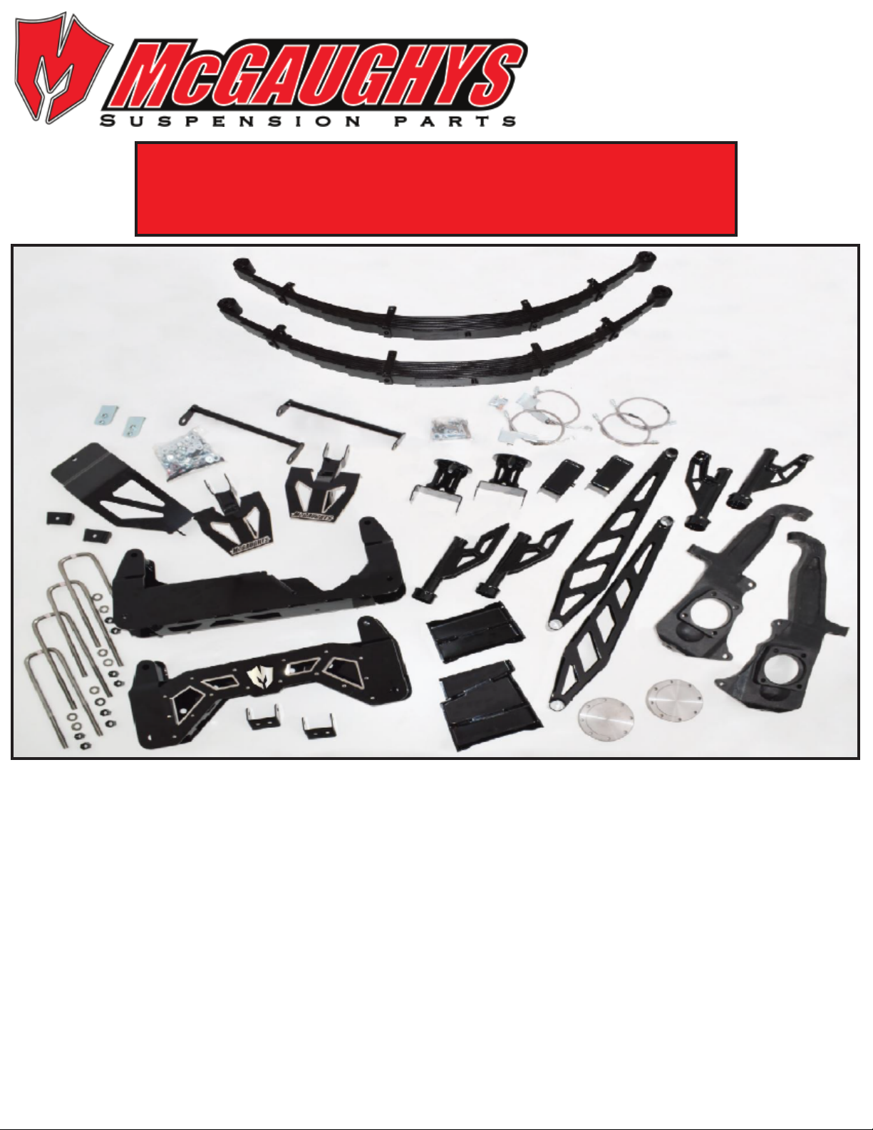
- Before moving forward with installation, please layout all parts from boxes
and ensure everything is present. If any parts are missing, please contact
McGaughy’s Suspension immediately at 559-226-8196.
- If you alter the nish of any of the provided components, like zinc plating,
chroming, or powder-coating, which can cause damage to the strength and
structure of the metal, any warranties will be null and void.
- If any components are ground on or modied in any way, then no returns or
exchages will be accepted and any warranties will be null and void.
- NO welding is required to install any part of this lift kit. Do not weld any
components.
- Over-sized tires and heavier wheels can cause premature wear on factory
and aftermarket components like ball joints, bushings, tie-rod ends, wheel
bearings, idler arms, drive-lines, etc.... You may need to replace / install new
components sooner than factory recommendations based on the tires and
wheels you choose. Please note that the heavier and wider wheels and tires
combined with aggressive driving (o-road and on highways) will cause more
wear on ALL moving parts, factory and aftermarket. Especially when vehicle is
in 4wd or Auto-4wd / AWD modes.
- Spindles and u-bolts are shipped with protective coating on surface. This
allows them to be delivered to you without rust. We recommend you clean
and paint the parts before you install, to protect against any future rust.
Remember, spindles and u-bolts are bare metal. And will rust without paint.
READ THESE ENTIRE INSTRUCTIONS
BEFORE STARTING ANYTHING

-McGaughy’s warrants all McGaughy’s products against manufacturer’s
defects in materials or workmanship for a period of ONE-YEAR from the date
of original purchase. All McGaughy’s spindles carry a LIFETIME warranty
against manufacturer’s defects.
-Warranty will not extend to any product or part there in, that has been
improperly installed, abused, or neglected
-McGaughy’s will not warranty any product(s) that were modied in any way.
Check t all products prior to custom painting, powder-coating, or any form
of fabrication (sanding, drilling, painting, chroming, etc).
-There are NO WARRANTIES neither espressed nor implied for powder-
coating on any McGaughy’s products.
-McGaughy’s is not responsible for damages and/or warranty of other vehicle
parts (factory or aftermarket) related or non-related to the install of
McGaughy’s component(s).
-Warranty is limited to the repair or replacement (of McGaughy’s product
only), at McGaughy’s discretion. And only after inspection of the defective
part, once returned to McGaughy’s with proof of purchase, date of purchase,
and all shipping costs prepaid.
-Any cost of labor, freight, incidental or consequential damages are expressly
excluded from warranty.
559-226-8196
4603 E. VINE AVE.
FRESNO, CA 93725
www.mcgaughys.com
WARRANTY INFORMATION

1. Leaf Springs
2. Compression Strut Nut Mounts
3. Lower A-Frame Support Rods
4. Hardware Bags
5. Front/Rear Brake Lines
6. Skid Plate
7. Front Bump Stop Retainer Brackets
8. Torsion Bar Drop Brackets
9. Rear Bump Stop Brackets
10. Lift Blocks
11. Front (Rear) Bump Stop Brackets
12. Lift Spindles
13. Compression Strut Bars
14. CV Axle Spacers
15. Front (Front) Bump Stop Brackets
16. Di Drop Brackets
17. Compression Strut Brackets
18. Front Crossmember
19. Rear Crossmember
20. U-Bolts
21. Sway Bar End Links (not pictured)
22. Front Driveline (not pictured)
23. Weld In Filler Plate (not pictured)
24. Front/Rear Shocks (not pictured)
10”-12” LIFT KIT INSTRUCTIONS
2011-2019 GM 2500 / 3500 TRUCKS
4603 E. VINE AVE
FRESNO, CA 93725
(559) 226-8196
3. 4. 5.
1.
6.
2.
11.
10.
9.
12.
8.
7.
13.
14.
15.
16.
17.
19.
18.
20.
4.

FRONT INSTALLATION
Always use the proper tools and consult the factory service manual for torque values
and procedures. With the vehicle turned o and the parking brake set, secure the
rear wheels/tires with wheel chocks. Use a jack and lift the front of the vehicle. Place jack stands under the frame
on both side of the vehicle. Remove the front wheels.
1. Disassemble the front. Start by disconnecting the ABS lines from the frame and the control arms.
2. Remove brakeline bracket from spindle using a 10mm socket.
3. Remove the factory sway bar end links using a 15mm wrench and socket.
4. Remove the factory skid plate using a 15mm socket.
5. Remove the factory tie rod ends from the spindles usinga 15mm socket.
6. Remove dust cap from rotor hub. Then remove CV axle nut using a 34mm socket.
7. Before disassembling torsion bars, be sure to mark the bars DRIVER side and PASSENGER side.
They need to be re-installed in the same location they are pulled from. This goes for the torsion
keys as well. Torsion bars must not be installed on opposite side or backwards. So mark front and
back on each bar too.
8. Before removing the bolt going through the block, be sure to mark the length at which it sits.
After it is marked, remove the bolt using a 21mm socket. (pic 1)
9. After the bolt is removed, use proper tool to clamp and remove the block. (pic 2)
10. Once block is out, remove torsion key by sliding torsion bar towards front of vehicle. (pic 3)
1. 2. 3.
11. Remove the torsion bar crossmember from vehicle, using 21mm wrench. Be sure you unplug
the wire from crossmember before removing it from vehicle.
12. Next, remove torsion bars from vehicle. Again, make sure they are both marked front and back,
and driver side and passenger side.
13. Remove the factory front shocks. Use 21mm socket and wrench for the lower bolt rst. Then use
a 21mm wrench to remove the top not.
14. After shocks have been removed, unbolt CV axle bolts using 17mm socket. (8 bolts per side)
15. Remove CV axles out of vehicle.
16. Unbolt brake calipers using 21mm socket, and secure up out of the way on the frame. Use zip
tie or wire to keep out of working space.
1.

2.
17. Remove factory spindles from vehicle, by loosening upper ball joint nut rst using 18mm
wrench. Then use 18mm socket to remove lower ball joint nut. Remove spindles from vehicle.
18. Remove lower control arms from vehicle, using 22mm and 24mm wrench and socket.
19. Remove lower control arm bump stop, by applying downward force to the stopper. (pic 4)
20. Remove front driveline using 11mm socket on the front half clamp. (pic 5)
21. Next remove rear strap over rubber boot using a athead srew driver. (pic 6)
4. 5. 6.
22. Support front dierential with a jack. Remove or unplug all electrical wires and vacuum lines
before removing dierential from vehicle. Slowly lower and remove dierential housing and rear
crossmember from
vehicle.
23. Use a die-
grinder or sawzall
to cut the inside of
the driver side
lower control arm
pocket. Measure
4.25” from the
inside and make a
vertical cut straight
down. (pic 7)
24. With the pocket cut out, you can now weld in the provide ller
plate. Be sure to test t rear crossmember before fully welding in
plate. Once test tted, you can now fully weld in the ller plate. Be sure to paint when done. (pic 8)
25. Install passenger side di drop bracket. Make sure open side with gusset is facing out towards
the tire. Smooth side will face inside. Taller end of bracket goes to the front of the vehicle. Use the
factory hardware to install to frame. (pic9)
26. Install driver side di drop bracket same way, with the smooth side facing in and gusset facing
out. Use the provided 12mm x 30mm bolts. (pic 10)
7. 8.

3.
27. With both di drop brackets installed, use jack to lift dierential into place.
28. Use the provided 1/2”-13 x 3-1/2” bolts and laser cut washers for the driver side. (pic 11) And use
the provided 1/2”-13 x 1-1/4”bolts for passenger side. Torque all bolts to 60lbs. Make sure to double
check that all bolts are tight. Now reconnect all electrical wires and vacuum lines to front dierential.
Make sure all wires and lines are out of the way of any moving parts.
9. 10. 11.
29. Install the new provided front driveline. Use the instructions within the driveline box.
30. Install the new provided front crossmember, using the factory hardware. Bolt heads should be
towards back of vehicle and the nuts facing towards the front. Now install the new rear cross-
member the same way. Using factory hardware and the bolt heads towards back of vehicle.
31. Now reinstall the factory lower control arms using the provided 18mm x 120mm bolts on the
front side (towards front of vehicle) and 18mm x 140mm on the rear side of the arms. (pic 12)
32. Before tightening up lower control arm, be sure to install the provided lower support rods.
12. 13.
33. Install new provided skid plate, using the provided 1/2”-13 x 4” bolt on the front crossmember
and 1/2”-13 x 1” bolt on the rear crossmemeber. After skid plate is installed, go back through and
tighten all hardware for front and rear crossmembers. Make sure lower A-frame support rods are
pushed up and ush againt welded tabs on crossmembers, before tightening. (pic 13) Also, make
sure lower control arms are parallel to the ground before tightening. Use a 27mm socket and wrench
to tighten.

4.
34. Install the front side
front bump stop brackets.
The upper bolt will only
titghen up against the
frame, to hold bracket in
place. (pic 14)
35. The lower bolt hole
will need to be drilled out
to 1/2”. After drilling, use
provided 1/2”-13 x 4”bolt,
washer, and top lock nut.
Be sure to use retainer
bracket on opposite side
of bump stop bracket.
(pic 15)
36. Now install rear side front
bump stop extender brackets. Use
the provided bolts with welded
tabs in the factory location.
(pics 16 / 17)
37. Use the provided 7/16” washers
and top lock nuts to install driver
side bracket (pic 18) and the
passenger side bracket (pic 19).
38. Now reinstall the factory bump
stops into the newly installed
drop brackets.
39. Install the new provided lift
spindles. Use the factory ball joint
nuts on the upper and lower.
Torque to factory specs.
40. Make sure to remove the
factory O-ring on the original
spindles and reinstall on the new
lift spindles. Next, install the hub
using the factory hardware and
provided loctite. Torque to factory
specs.
15.14.
16. 17.
18. 19.

5.
41. Reinstall factory CV axles to the back
side of the hub. Before bolting into place,
install the provided CV axle spacers onto
ange. Use provided 10mm x 50mm
hardware and loctite. (pic 20)
42. Install the compression strut bars. Start
by bolting the front of compression strut
to the back side of the rear crossmember.
Hand tighten only. Next, bolt the rear
compression strut brackets to the rear of
the compression struts. Hand tighten only.
Now swing compression struts up until the
rear bracket meets
the transmission
crossmember. Mark
the location where
you will need to
drill. Once marked,
let the compression
struts hang out of
the way. Now drill
out the marked spots to 1/2”. With the holes
drilled out, slide the provided compression strut retainer nut brackets (pic 21) into the transmission
crossmember so the nuts line up with the holes. (pic 22)
43. Now swing the compression strut bars up and bolt into place using the provided 1/2”-13 x 4”
hardware. torque to 75lbs. (pic 23)
20.
22.
21.
23.
This kit comes with new stainless steel braided brake lines.
Brake lines should be installed by a GM Certied Technician
When installing, refer to GM Hydraulic Brake System Manual with any questions
44. Disconnect rubber line from steel line. Remove any brackets to the rubber line. Remove banjo
bolts to re-use. Do not re-use banjo washers, you will use the new provided washers.
45. Install new brake lines to steel lines on the frame. Secure with supplied retainer clips. (pic 24)
46. Place new banjo washer onto original banjo bolt and install through tting. Place new banjo
washer on opposite
side of tting. (pic 25)
47. Now install to
caliper. Torque to
factory specs.
48. Tighten upper
brake line tting to
factory specs as well.
24. 25. 26.

REAR INSTALLATION
With the vehicle turned o and the parking brake set, secure the front wheels/tires with
wheel chocks. Use a jack and lift the rear of the vehicle. Place jack stands under the
frame on both side of the vehicle. Remove the rear wheels.
6.
44. Use provided adel clamp to secure new brake lines to lift spindles. There is a 1/4”-20 tapped hole
on back of spindle. Use provided bolt to install. (pic 26)
45. After all lines are installed, bleed brakes by following the GM Brake System Manual. Bleeding of
brakes should be performed by a GM Certied Technician.
46. The factory ABS line that runs from your hub to the spindle needs to be run along the new brake
line. Use the provided zip ties to secure the line to new brake line. Make sure the ABS line and all
brake lines are away from any moving parts. Turn wheels left to right to make sure none of the lines
get hung up or caught on anything. Make sure everything has enough slack to move easily.
47. Install the new provided sway bar end links in the factory locations.
27. 28. 29. 30.
48. Use the provided 9/16” x 3-1/2” hardware to install the new torsion bar
drop brackets into the factory mounts. (pic 27)
49. Install the factory torsion bar crossmember into the new drop brackets, using the factory
hardware. (pic 28) Use the provided 3/8”x 1-1/4”hardware from the bottom of the torsion bar
crossmember into the new drop brackets. (pic 29)
50. Tighten all bolts on torsion bar crossmember and drop brackets. Start from bottom bolts and
work up, untill all hardware is tight. (pic 30)
51. Reinstall the factory torsion bars into the lower arms and crossmember. Make sure they are
installed the same way they were taken o the vehicle. Using the proper torsion key tool, apply
pressure on the key to reinstall the factory block. Thighten bolt back to the stock position you
marked earlier. Make sure you secure reconnect any abs lines you loosened earlier as well.
52. Support the rear end with a jack.
53. Remove ABS wires from both sides of the frame, disconnect at the plug.
54. Using a 21mm socket and wrench, remove the factory shocks from the vehicle.
55. Disconnect brake line bracket on driver side using 13mm socket. (pic 31) Remove emergency
brake line brackets on driver side using 13mm socket. (pic 32-34)
31. 32. 34.33.

7.
56. Install supplied bracket, by
connecting cable line in place
and lining bracket to frame.
(pic 35)
57. Scribe hole onto frame, for
bracket, and dill out to 7/16”.
(pic 36) Use provided
7/16”-14 x 1-1/4” hardware to
install bracket. (pic 36-37)
35.
36. 37.
58. Reinstall parking brake line to
the frame. Be sure to allow 1/4”
of thread to protrude through
nut.
59. Install parking brake drop
bracket to factory holes on driver
side. (pic 38)
60. Place original parking brake hanger on lower hole of drop
down bracket. Use 1/4”-20 x 1” hardware to bolt hanger to bracket
using the upper hole. (pic 39)
61. With the rear end supported with jack, and only doing one side at a time. Loosen the nuts on the
front and back of the leaf spring. Do not remove the bolt yet. Then remove the u-bolts and plate.
62. Now take the bolts out and remove the leaf spring from the vehicle. You will need to use “C”
clamps on the factory leaf pack to remove the center pin and u-bolt retainer plate. The factory
retainer plate must be reinstalled onto the new provided leaf pack. Use the same process to re-
install the retainer plate on new leafs as you did to remove it from the factory leaf pack.
63. Install the new leaf spring onto the vehicle using the factory hardware. Place the provided lift
block between the leaf pack and the rear end. Tall side of the lift block faces towards the rear of the
vehicle. If you are adding the rear lift shims, you can install them now between the lift block and
leaf spring. Use the provided u-bolts and the factory retainer plates to secure rear end. Do not fully
tighten yet. WIth the rst side complete, now do the same process on the opposite side of the
vehicle. When both side are complete, you can then torque all the u-bolts to 175lbs. Be sure to
tighten in a “X” pattern.
64. Make sure you plug the ABS wires back into place at this time.
38. 39.

8.
65. Do not forget to tighten the front and rear bolts on both leaf springs. Check all the bolts on the
shackles as well, to make sure they are still tight. Torque all hardware to factory specs.
66. Remove the factory brake line bracket
on the driver side of rear end. You will
reinstall it once the new bump stop
extender is in place. Place the driver side
bump stop extender in place and bolt on
using supplied hardware and factory
hardware with factory brake line bracket.
(pic 40)
67. Now do the same proccess on the
passenger side. Remove the factory brake
line bracket and reinstall it along with the
new bump stop extender. (pic 41)
40. 41.
This kit comes with new stainless steel braided brake lines.
Brake lines should be installed by a GM Certied Technician
When installing, refer to GM Hydraulic Brake System Manual with any questions
68. This kit will come with three new brake lines for the rear. If your vehicle is equipped with
Stabilitrak, then you will use the two brake lines. If your vehicle does not have Stabilitrak, then you
will only use the single brake line.
69. Disconnect and remove tting rubber and steel at both ends of factory brake lines.
70. Install new braided lines at each end, connecting to steel tting at frame and at rear end. Tighten
both ends of lines to factory torque specs.
71. Secure new lines with provided clips, so they do not twist. Make sure all lines are away from any
moving parts.
72. After all lines are installed, bleed brakes by following the GM Brake System Manual. Bleeding of
brakes should be performed by a GM Certied Technician.
73. This kit includes front and rear reservoir shocks. Reservoirs can be bolted on to shock body using
the supplied clamp mounts. Install front and rear shocks using the factory hardware.
* Double check all of the front and rear fasteners and components, making sure everything
has been torqued to the proper specications. This MUST be done before operating the
vehicle.
* Vehicle MUST be properly aligned before driving.
* After 500 miles, be sure to go over all of the front and rear suspension and lift components
to make sure nothing has come loose and everything is still tight.
* We recommend periodically checking all of the front and rear suspension and lift
components to be sure they are tight and in proper working order.
This manual suits for next models
1
Table of contents
Popular Automobile Accessories manuals by other brands

Power Fist
Power Fist 4200186 user manual

FormFit
FormFit 18200 installation instructions

FormFit
FormFit HD 13B13 installation instructions

MediaTech
MediaTech BLUETOOTH EARSET MT3529 instruction manual

Vanguard
Vanguard VG284-3 Fitting instructions

Vision Drive
Vision Drive HD BLACK BOX VD-8000HD user manual