manuals.online logo
Brands
  1. Home
  2. •
  3. Brands
  4. •
  5. McIntosh
  6. •
  7. Amplifier
  8. •
  9. McIntosh MA6700 Guide

McIntosh MA6700 Guide

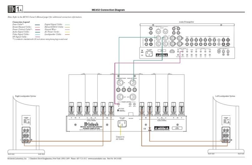
MA/MAC6700 Rear Panel Connections
1A
McIntosh Laboratory, Inc. 2 Chambers Street Binghamton, New York 13903-2699 Phone: 607-723-3512 FAX: 607-724-0549 Part No. 04142300
MA6700 / MAC6700
Connect the MA/MAC6700 power
cord to a live AC outlet. Refer to
information on the back panel of
your MA/MAC6700 to determine
the correct voltage for your unit
POWER CONTROL MAIN
Output sends turn On/Off
signals to a McIntosh Compo-
nent when the MA/MAC6700 is
switched On/Off
DATA PORTS send
signals to Source Com-
ponents to allow control
with the MA/MAC6700
Remote Control
GND terminal
accepts a ground
wire from a
turntable
RECORD OUT
sends signals to
the input of a
recording device
PHONO MM accepts
signals from a Mov-
ing Magnet Phono
Cartridge
SRVR(REC), DVD, CD2,
CD and AUX INPUTS
accept high level program
source signals
PASSTHRU Power
Control Input receives
turn On/Off signals
from an Audio/Video
Control Center
PHONO MC accepts
the low level signals
from a Moving Coil
Phono Cartridge
OUTPUTS 1 and 2 send signals
to Power Amplifiers and are
switched On/Off with the Front
Panel Output 1 and 2 Push-
Buttons or Remote Control
Push-Buttons
DIGITAL AUDIO INPUTS
for components with Digital
Optical (1) and Coaxial (2)
Outputs sending digital
audio signals
BALanced INPUTS
accept high level pro-
gram source signals
USB D/A Digital
Audio Input for
connection to a
computer
RS232-C connector1
for connection to a
computer or other
control device
IR INput for
signals from a
compatible IR
Room Sensor
POWER CONTROL TRIGger
outputs 1 and 2 send turn On/
Off signals to assignable com-
ponents
Main Fuse holder, refer to
information on the back
panel of your MA/MAC6700
to determine the correct fuse
size and rating
PWR AMP input
accepts signals
from the internal
Preamplifier or a
separate external
Preamplifier
LEFT OUTPUT
connections for a
2, 4 or 8 ohm
loudspeaker
JUMPER PLUGS con-
nect the Preamplifier
OUTPUT 1 Jacks to the
PWR AMP IN Jacks and
are required for normal
operation
RIGHT OUTPUT
connections for a
2, 4 or 8 ohm
loudspeaker
1Refer to page 5 of the MA/MAC6700 Owner’s
Manual for addition cable information.
Reserved for the instal-
lation of optional Tuner
Module for the MA6700.
A Tuner Module is factory
installed in the MAC6700
MA6700 Tuner Module Installation and Connecting Antennas
1B
McIntosh Laboratory, Inc. 2 Chambers Street Binghamton, New York 13903-2699 Phone: 607-723-3512 FAX: 607-724-0549
CAU TION: To prevent the risk of electric
shock, first remove the AC Power
Cord from the MA6700 Rear Panel
before in-
stalling the
TM Mod-
ule into the
MA6700.
1. The semiconductor
devices used in the
TM Module are inherently sensitive to static
electricity even when connected in a circuit,
and can be permanently
damaged by a static
electricity discharge.
When handling the TM
Module follow the pro-
cedures below to insure
against static electricity
damage.
A. Make sure the MA6700 is properly
grounded.
B. Use an approved wrist strap that is
grounded.
C. Remove the TM Module from the Anti-
Static Bag and work with it only after the
above conditions have been met.
General Information
The McIntosh TM2 or TM3 Tuner Module
together with the McIntosh RAA2 AM Antenna
adds AM and FM Radio Broadcast Reception to
the MA6700 Integrated Amplifier. The instruc-
tions in this guide are for installing the TM2 or
TM3 into the MA6700.
The TM2 and TM3 Tuner Modules are not a
user installable product. It must be installed by
the Technical Professionals at a McIntosh Dealer
only.
Installing the Tuner Module
1. If the MA6700 Integrated Amplifier is con-
nected to AC Power, remove the AC Cord
from the Rear Panel.
2. Remove two screws from the MA6700 Rear
Cover and retain the two screws as they will
be used later to secure the Tuner Module.
Refer to figure 1 and 2.
Note: Retain the cover for possible future use.
3. Using the safe handling procedure outlined,
in the “General Information”, remove the
Tuner Module from the Anti-Static Bag.
4. Orient the Tuner Module so the electronic
component parts on the PC Board are facing
upwards and line up the side edges of the
tuner module with the PC Board Guides lo-
cated inside the MA6700 Metal Cage. Refer
to figures 2, 3A (TM2) or 3B (TM3).
5. Insert the Tuner Module all the way into
the MA6700 and secure the Tuner Module
Metal Plate to the rear panel of the MA6700
with the two previously removed screws. Re-
fer to figures 4A (TM2) or 4B (TM3).
6. Proceed to “Connecting the Tuner Module”
to the external Antennas.
Connecting Antennas
TM2 TM3
RAA2 Figure 1
Remove Screws
Remove Cover
Figure 2
PC Board Guides
Figure 4A
Figure 4B
Fig ure 3A
TM2
Figure 3B
TM3
Figure 5A
Figure 5B
Tune to a station with the weakest signal and ori-
ent the RAA2 Antenna for maximum signal with
minimum noise and
distortion. After the
location is determined,
the RAA2 AM An-
tenna may be secured
to a suitable surface by
using two #6 1-3/4 to 2
inches (4.44 to 5.08cm)
long screws, refer to the illustration to the right.
Mounting the RAA2 AM Antenna
1. Using the supplied AM Antenna Shielded
Cable, connect one end into the RAA2 AM
Antenna jack and the other end of the same
cable into the MA6700 Tuner jack labeled
RAA2 AM ANT. Refer to figure 5A with
a TM2 installed and figure 5B with a TM3
installed.
Note: If a longer AM Antenna Cable is needed,
refer to page 5 “Connector and Cable
Information”.
2. Connect a FM Dipole Antenna to the
MA6700 75 Ohm FM ANT Connector. Refer
to figure 5A for a TM2 installed and figure
5B for a TM3.
Note: Optionally, connect a 75 ohm coax
cable from a FM Antenna or cable sys-
tem. For more information about a FM
Dipole Antenna, refer to page 5.
3. Proceed to “Connecting Loudspeakers” in
the MA6700 Owner’s Manual page 14.
Tune to a station with the weakest signal and ori-
ent the top of the “T” shaped Dipole Antenna for
maximum signal with
minimum noise and
distortion. After the
location is determined,
the FM Dipole An-
tenna may be secured
to a suitable surface
by using push pins, refer to the illustration to the
right.
Mounting the FM Dipole Antenna
TM3
TM2
FM Dipole
Antenna
FM Dipole
Antenna
Other manuals for MA6700

2

This manual suits for next models

1

Other McIntosh Amplifier manuals

McIntosh MC601 User manual

McIntosh

McIntosh MC601 User manual

McIntosh MC58 User manual

McIntosh

McIntosh MC58 User manual

McIntosh MA6600 Instruction manual

McIntosh

McIntosh MA6600 Instruction manual

McIntosh C42 User manual

McIntosh

McIntosh C42 User manual

McIntosh MA6300 User manual

McIntosh

McIntosh MA6300 User manual

McIntosh MA7000 User manual

McIntosh

McIntosh MA7000 User manual

McIntosh MC 22O5 Operating and installation instructions

McIntosh

McIntosh MC 22O5 Operating and installation instructions

McIntosh C1000 User manual

McIntosh

McIntosh C1000 User manual

McIntosh C30 User manual

McIntosh

McIntosh C30 User manual

McIntosh MCC602TM User manual

McIntosh

McIntosh MCC602TM User manual

McIntosh MC225 User manual

McIntosh

McIntosh MC225 User manual

McIntosh MC501 User manual

McIntosh

McIntosh MC501 User manual

McIntosh C70 Instruction manual

McIntosh

McIntosh C70 Instruction manual

McIntosh MC3500 User manual

McIntosh

McIntosh MC3500 User manual

McIntosh C20 - User manual

McIntosh

McIntosh C20 - User manual

McIntosh MC275 User manual

McIntosh

McIntosh MC275 User manual

McIntosh MC207 User manual

McIntosh

McIntosh MC207 User manual

McIntosh MC2102 User manual

McIntosh

McIntosh MC2102 User manual

McIntosh C8 - SCHEMATICS User manual

McIntosh

McIntosh C8 - SCHEMATICS User manual

McIntosh MC275 User manual

McIntosh

McIntosh MC275 User manual

McIntosh MCC204 User manual

McIntosh

McIntosh MCC204 User manual

McIntosh MC-2105 User manual

McIntosh

McIntosh MC-2105 User manual

McIntosh A-116 User manual

McIntosh

McIntosh A-116 User manual

McIntosh C34V User manual

McIntosh

McIntosh C34V User manual

Popular Amplifier manuals by other brands

Ramsey Electronics QAMP20 Assembly and instruction manual

Ramsey Electronics

Ramsey Electronics QAMP20 Assembly and instruction manual

Amperes PA330 instruction manual

Amperes

Amperes PA330 instruction manual

Ericsson 19D902797G1 Maintenance manual

Ericsson

Ericsson 19D902797G1 Maintenance manual

Digital audio Livemix System quick start guide

Digital audio

Digital audio Livemix System quick start guide

Raymer 808-60 operating instructions

Raymer

Raymer 808-60 operating instructions

Mackie M-2600 Service manual

Mackie

Mackie M-2600 Service manual

ProAudio DZ1604 user manual

ProAudio

ProAudio DZ1604 user manual

AVPro Edge ConferX AC-CX100-RAMP user manual

AVPro Edge

AVPro Edge ConferX AC-CX100-RAMP user manual

Kramer VP-200K user manual

Kramer

Kramer VP-200K user manual

Pioneer SA-900 manual

Pioneer

Pioneer SA-900 manual

Paul C. Buff Vagabond II quick start guide

Paul C. Buff

Paul C. Buff Vagabond II quick start guide

Kramer VP-200K user manual

Kramer

Kramer VP-200K user manual

KAHAYAN Proaudio 12K72 Series Operator's manual

KAHAYAN Proaudio

KAHAYAN Proaudio 12K72 Series Operator's manual

JL Audio M800/8-24V owner's manual

JL Audio

JL Audio M800/8-24V owner's manual

RF-Tuote SMART mini user manual

RF-Tuote

RF-Tuote SMART mini user manual

Channel Vision A0362 instructions

Channel Vision

Channel Vision A0362 instructions

Kenwood KAC-644 instruction manual

Kenwood

Kenwood KAC-644 instruction manual

Rockbox Matador manual

Rockbox

Rockbox Matador manual

manuals.online logo
manuals.online logoBrands
  • About & Mission
  • Contact us
  • Privacy Policy
  • Terms and Conditions

Copyright 2025 Manuals.Online. All Rights Reserved.