manuals.online logo
Brands
  1. Home
  2. •
  3. Brands
  4. •
  5. McIntosh
  6. •
  7. Amplifier
  8. •
  9. McIntosh MX113 Operating and installation instructions

McIntosh MX113 Operating and installation instructions

c
McIntosh
MX
113
AM/FM
TUNER
PREAMP
SERVICE
INFORMATION
STARTING
WITH
SERIAL
NO.
100H1
r
McIntosh
laboratory
inc.
2
chambers
street
binghamton,
new
york
MX
113
r
MX
113
SENSITIVITY
75pV
IHF
(external
ant.)
ELECTRICAL
SPECIFICATIONS
AM
TUNER
SECTION
SELECTIVITY,
ADJACENT
CHANNEL
35
dB
minimum
IHF
in
"NORMAL"
Position.
1+5
dB
minimum
IHF
in
"NARROW"
Position.
SIGNAL
TO
NOISE
RATIO
1+5
dB
IHF
minimum;
55
dB
at
100%
modulation.
HARMONIC
DISTORTION
Does
not
exceed
1%
at
30%
modulation.
IMAGE
REJECTION
65
dB
minimum
5^+0
kHz
-
1600
kHz.
FREQUENCY
RESPONSE
3.5
kHz
-
6
dB,
"NORMAL"
Position.
2.1
kHz
-
6
dB,
"NARROW"
Position.
FM
TUNER
SECT
ON
USEABLE
SENSITIVITY
2.5
microvolts
at
100%
modulation
(+75
kHz
deviation)
for
3%
total
noise
and
harmonic
distortion
IHF.
S
IGNAL
TO
NOISE
RAT
10
70
dB
below
100%
modulation.
CAPTURE
RAT
10
1
.5
dB
HARMONIC
DISTORTION
Mono:
Does
not
exceed
0.3%
at
100%
modulation
j+75
kHz
deviation.
Stereo:
Does
not
exceed
0.5%
AUDIO
FREQUENCY
RESPONSE
_+l
dB
20
Hz
to
15,000
Hz
with
standard
de-emphasis
(75
psec.)
and
19,000
Hz
pilot
filter.
SELECTIVITY
ADJACENT
CHANNEL:
6
dB
minimum
IHF
in
"NORMAL"
Position.
15
dB
minimum
IHF
in
"NARROW"
Position.
ALTERNATE
CHANNEL:
58
dB
minimum
IHF
in
"NORMAL"
Position.
88
dB
minimum
IHF
in
"NARROW"
Position.
SPURIOUS
REJECTION
90
dB
IHF
minimum.
IMAGE
REJECTION
95
dB
minimum,
88
MHz
-
108
MHz.
STEREO
SEPARAT
ION
35
dB
at
I,000
Hz.
SCA
FILTER
50
dB
rejection
from
67
kHz
to
Ik
kHz.
275
dB
per
octave
slope.
PREAMPLIFIER
SECTION
FREQUENCY
RESPONSE
+0.5
dB,
20
Hz
to
20,000
Hz.
DISTORTION
Less
than
0.1%
at
2.5
volts
20Hz
to
20
kHz.
INPUT
SENSITIVITY
(phono
1
and
phono
2)
2
millivolts
for
2.5
volts
output
at
1
kHz.
OUTPUT
(tape)
0.25
volts
with
rated
input.
Phono
input
signal
of
10
millivolts
produces
1.2
volts
output.
FM
and
AM
will
produce
1.2
volts
output
at
100%
modulation.
OUTPUT
(center
channel)
2
volts
with
rated
input
to
both
channels.
BASS
CONTROL
INPUT
SENSITIVITY
(aux,
tape)
0.25
volts
for
2.5
volts
output.
-18
dB
to
+16
dB
at
20
Hz.
TREBLE
CONTROL
HUM
AND
NOISE
(phono
1
and
phono
2)
72
dB
below
10
millivolt
input.
+20
dB
to
20,000
Hz.
LF
FILTER
HUM
AND
NOISE
(aux,
tape)
85
dB
below
rated
output.
OUTPUT
(main)
2.5
volts
with
rated
input.
Up
to
10
volts
can
be
developed
without
distor¬
tion.
FM
and
AM
will
produce
up
to
10
volts
output
at
100%
modulation.
Flat
or
roll
off
below
50
Hz,
down
12
dB
at
20
Hz.
HF
FILTER
Flat
or
roll
off
above
5000
Hz,
down
12
dB
at
20,000
Hz.
MX
113
SCHEMATIC
NOTES
1.
Unless
otherwise
specified:
Resistance
values
are
in
ohms,
1/4
watt,
and
10%
tolerance;
capacitance
values
smaller
than
1
are
in
microfarads
(pF);
capacitance
values
greater
than
1
are
in
picofarads
(pF);
inductors
are
in
microhenries
(pH).
?•
3.
4.
5.
6
.
b.
c.
d.
Printed
circuit
board
components
are
outlined
on
the
schematics
by
dotted
lines.
The
circled
numbers
around
the
dotted
lines
correspond
to
the
numbers
on
the
PC
Board
layouts.
The
heavy
lines
on
the
schematics
denote
the
primary
signal
path.
The
terminal
numbering
of
rotary
switches
is
for
reference
only.
All
voltages
indicated
on
the
schematics
are
measured
under
the
following
conditions:
a.
Use
of
an
11
megohm
input
impedance
VTVM.
All
voltages
+10%
with
respect
to
chassis
ground.
No
signal
at
input
or
antenna
terminals.
AC
input
at
120
volts,
50/60
Hz.
Front
panel
controls
at:
Tuning
indicator
100
MHz
(no
signal)
Fully
CCW
Stereo
Out
AM
(to
measure
AM
section)
FM
(to
measure
FM
section)
Panel
Lights
Bright
Selectivity
Out
f.
Voltages
shown
in
rectangles
are
measured
with
selectivity
switch
in
the
"In"
position.
In
units
with
serial
no.'s
below
187H5
R219
and
R225
are
used.
Volume
Mode
Muting
Input
Selector
7.
In
units
with
serial
no.'s
below
190H0
R329
and
R330
are
15K;
C8
js
12pF
R528
is
used;
D505
and
D506
are
not
used
and
R530
is
connected
as
shown
by
dotted
line.
8.
In
units
with
serial
no.'s
below
178H9
C38
is
3pF;
C527
and
C528
are
not
used
and
dial
glass
is
McIntosh
part
no.
044-359.
9.
In
units
with
serial
no.'s
below
189H4
C505
is
.02pF.
10.
In
units
with
serial
no.'s
from
175HO
to
190H0
C527
and
D504
are
used.
11.
In
units
with
serial
no.'s
below
199H9
C124
is
used
and
C402
is
lOOpF.
12.
In
units
with
serial
no.'s
from
167H5
to
178H8
C101
and
C108
is
not
used.
13.
In
units
with
serial
no.'s
below
182H5
R408
is
680fi;
R411
is
10K;
R412
and
R418
are
used.
14.
In
units
with
serial
no.'s
from
238H2
to
282H6
C213
is
used.
In
units
with
serial
no.'s
below
282H6
R203
is
used
and
L201
is
not
used.
15.
In
units
with
serial
no.'s
below
322H6
R337
and
R338
is
1.8k.
16.
In
units
with
serial
no.'s
below
269H6
the
MPX
Lamp
is
a
#1828
bulb
and
r
419
is
used.
17.
In
units
with
serial
no.'s
below
262H1
C214
is
not
used.
18.
In
units
with
serial
no.'s
below
400H
1
:
R399
and
R400
are
1M;
C303,
C304,
C3
1
3
&
C3
i
4
are
used;
C346,
C347,
C348,
C349,
C350,
C351,
R399-2
and
R399-3
are
not
used
and
c4
1
5
is
,22pF.
19.
In
units
with
serial
no.'s
below
282H6:
C413
is
.lpF;
R415
and
R416
are
used;
Q407
is
not
used
and
D407
is
connected
as
shown
by
dotted
lines.
20.
In
units
with
serial
no.'s
below
334H9
R530
is
7.5k
and
D505
is
McIntosh
Part
No.
070047.
21.
In
early
units
R526
is
not
used.
22.
In
early
units
CIO
and
C35
are
.OOlpF.
TUNING
CONDENSER
DRUM
113
(TO
IDLER
PULLEY
AND
TUNING
SHAFT)
BLACK
MX
113
R
F
CHASSIS
IF
PC
BOARD
044-277
/-NOTE
12
RI06
IF
OUT
TO
PREAMP
SECTION
TUNER
SECTION
154-647
LEFT
CHANNEL
INPUTS
TAPE
<
AUX.
(
TAPE
OUT
(
RIGHT
CHANNEL
INPUTS
TAPE
(
AUX.
<
TAPE
OUT
(
MOTE
16.
C
351
RED/
1
io
COAX
ov|
c
3CJ
—
O
<
rr
-v
_.
A
BLK/
1
r^0-
L
Q
SECTION
2
REAR
_iL-
(^.
•XJ
1
_
7
oS*
LEFT
FM
INPUT
■
£>
♦
£>
♦
(FROM
MPX
SEC'
AM
INPUT
-m-t
(FROM
TUNER
SECTION)
0>^
RIGHT
FM
INPUT
£S$
(FROM
MPX
SECTION)!
’Wv
SECTION
I
-
FRONT
SECTION
3-FRONT
SECTION
3
REAR
VIO/
I
,,
wht/^n
9.5
y
<)
■
J
RED/
I
R
310
R3I6
-VAr^-Wv*
l.SM
68
K
T
I
BLX/
I
si;
•*>
^
x
io
-r*
£
a
<
o
u
-1
a.
LEFT
CHANNEL
PREAMP.
PRINTED
CIRCUIT
BOARD
044-554
MX
113
N
TO
PIN
5
S30I-
I
REAR
<FM
SECTION)
IN
-NARROW
MX
113
MPX
PC
BOARD
044-299
o
R407
25K
I
MUTING
APJI
-I.5V
JL
GRY/WHT
-
(|4>-
MPX
PC
BOARD
044-299
C409
FROM
FM
OUTPUT
OF
TUNER
SECTION
24V
O
0401
"
6.3V
R404
>
N
o
J
S
~
^
*"
s
°
R428
3K
5%
00
*D
tz
o
X
<^WV-
„
47
'-NOTE
1
L
402
19
hH*
PHASE
AOJ.
*
1
in
|
*|
|
_
NOTE
19-K
*
D404
«*
i
-n-l
i
>
*»
*
J040«
V
r
S
y
4-
“
^7V
'
N^R408
C408
,
1/
R414
C4I2
-
i
\
220
^
f*:
5
"
4T
cm
o
lk
—
a
1
1
\\
100
25V
22
K
IT
*
.0027
R413
r
100
K
if

Other manuals for MX113

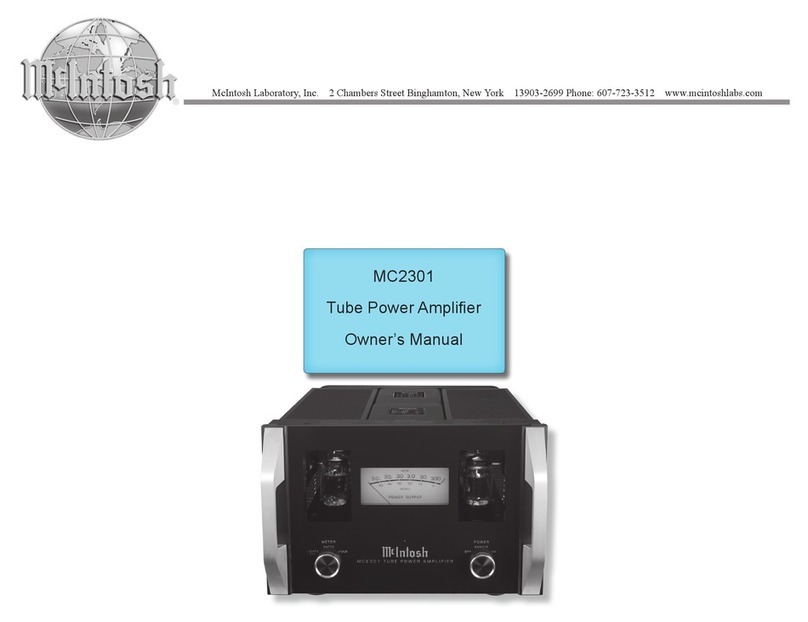
1

Other McIntosh Amplifier manuals

McIntosh C34V User manual

McIntosh

McIntosh C34V User manual

McIntosh MHA50 User manual

McIntosh

McIntosh MHA50 User manual

McIntosh MC7205 User manual

McIntosh

McIntosh MC7205 User manual

McIntosh C2700 User manual

McIntosh

McIntosh C2700 User manual

McIntosh C1000 User manual

McIntosh

McIntosh C1000 User manual

McIntosh C30 User manual

McIntosh

McIntosh C30 User manual

McIntosh C33 User manual

McIntosh

McIntosh C33 User manual

McIntosh MA6500 User manual

McIntosh

McIntosh MA6500 User manual

McIntosh MC-60 User manual

McIntosh

McIntosh MC-60 User manual

McIntosh MC 2120 User manual

McIntosh

McIntosh MC 2120 User manual

McIntosh MA9500 User manual

McIntosh

McIntosh MA9500 User manual

McIntosh C15 User manual

McIntosh

McIntosh C15 User manual

McIntosh MI347 User manual

McIntosh

McIntosh MI347 User manual

McIntosh C28 User manual

McIntosh

McIntosh C28 User manual

McIntosh MC225 User manual

McIntosh

McIntosh MC225 User manual

McIntosh 60TH ANNIVERSARY SYSTEM - annexe 1 User manual

McIntosh

McIntosh 60TH ANNIVERSARY SYSTEM - annexe 1 User manual

McIntosh C200 User manual

McIntosh

McIntosh C200 User manual

McIntosh MA6900 User manual

McIntosh

McIntosh MA6900 User manual
McIntosh C 504 User manual

McIntosh

McIntosh C 504 User manual

McIntosh MX120 User manual

McIntosh

McIntosh MX120 User manual

McIntosh MC602 User manual

McIntosh

McIntosh MC602 User manual

McIntosh C220 User manual

McIntosh

McIntosh C220 User manual

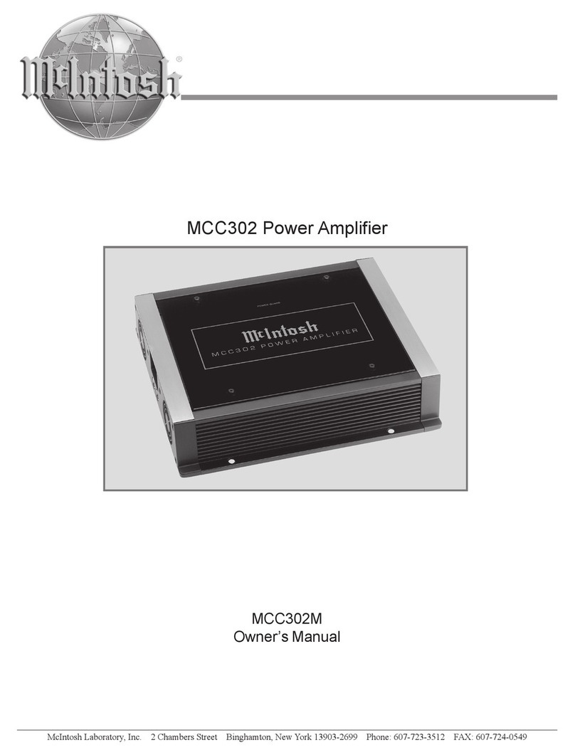
McIntosh MCC302 User manual

McIntosh

McIntosh MCC302 User manual

McIntosh MC2152 User manual

McIntosh

McIntosh MC2152 User manual

Popular Amplifier manuals by other brands

Gemini X-01 Operation manual

Gemini

Gemini X-01 Operation manual

Dual DMA804D Installation & owner's manual

Dual

Dual DMA804D Installation & owner's manual

Line Magnetic LM-150IA Operation manual

Line Magnetic

Line Magnetic LM-150IA Operation manual

Pyle PFA330BT user manual

Pyle

Pyle PFA330BT user manual

VINCENT PHO-701 Instructions for use

VINCENT

VINCENT PHO-701 Instructions for use

opticis SPIDER OVD12 user manual

opticis

opticis SPIDER OVD12 user manual

Abtus CAT-RGB Series User's operation guide

Abtus

Abtus CAT-RGB Series User's operation guide

Cobalt Digital Inc 9910DA-AV-EQ product manual

Cobalt Digital Inc

Cobalt Digital Inc 9910DA-AV-EQ product manual

OWI AMP4IC6 Specifications

OWI

OWI AMP4IC6 Specifications

Cross Technologies 2412-x08 instruction manual

Cross Technologies

Cross Technologies 2412-x08 instruction manual

Kenwood KAC-719 instruction manual

Kenwood

Kenwood KAC-719 instruction manual

Vonyx VPA300 instruction manual

Vonyx

Vonyx VPA300 instruction manual

Arcam Alpha 5 Service manual

Arcam

Arcam Alpha 5 Service manual

Bogen NQ-PA120 Configuration guide

Bogen

Bogen NQ-PA120 Configuration guide

CANARY AUDIO CA-330 owner's manual

CANARY AUDIO

CANARY AUDIO CA-330 owner's manual

Marshall Amplification MG10 Review

Marshall Amplification

Marshall Amplification MG10 Review

Hughes & Kettner Triplex Service documentation

Hughes & Kettner

Hughes & Kettner Triplex Service documentation

Nexo NXAMP 4x1 manual

Nexo

Nexo NXAMP 4x1 manual

manuals.online logo
manuals.online logoBrands
  • About & Mission
  • Contact us
  • Privacy Policy
  • Terms and Conditions

Copyright 2025 Manuals.Online. All Rights Reserved.