McIntosh MSE1 User manual

McIntosh Laboratory, Inc. 2 Chambers Street Binghamton, New York 139 3-2699 Phone: 6 7-723-3512 FAX: 6 7-724- 549
Owners
Manual
MSE1
Surround Expander

2
Thank You .......................................................................... 2
Please Take a Moment ....................................................... 2
Technical Assistance .......................................................... 2
Customer Service............................................................... 2
Table of Contents ............................................................... 2
Safety Instructions ............................................................. 3
Introduction .......................................................................
Performance Features ........................................................
Dimensions ........................................................................ 5
Installation ......................................................................... 6
Rear Panel Switches and Connections .............................. 7
How to Connect with a MX132......................................... 8
How to Connect with a C39/MX130
and MSD or MAC3 ....................................................... 10
How to Connect with a MSD or MAC-3....................... 12
Front Panel Controls, Displays, Push-Buttons,
and Switch ....................................................................... 1
Speaker Settings .............................................................. 15
Surround Calibrations ...................................................... 16
How to Operate................................................................ 19
Specifications .................................................................. 22
Packing Instruction .......................................................... 23
Table of Contents
1. The following Connecting Cable is available from the
McIntosh Parts Department:
Data and Power Control Cable Part No. 170-202
Six foot, shiel e 2 con uctor, with 1/8 inch stereo mini
phone plugs on each en .
2. For a itional connection information, refer to the owners
manual(s) for any component(s) connecte to the MSE1
Surroun Expan er.
Customer Service
Technical Assistance
Please Take A Moment
Thank You
Copyright 2000 ã by McIntosh Laboratory, Inc.
The serial number, purchase date and McIntosh dealer
name are important to you for possible insurance claim or
future service. The spaces below have been provided for
you to record that information:
Your decision to own this McIntosh MSE1 Surround Ex-
pander ranks you at the very top among discriminating mu-
sic listeners. You now have The Best. The McIntosh
dedication to Quality, is assurance that you will receive
many years of musical enjoyment from this unit.
Please take a short time to read the information in this
manual. We want you to be as familiar as possible with all
the features and functions of your new McIntosh.
Serial Number:
Purchase Date:
Dealer Name:
If it is determined that your McIntosh product is in need of
repair, you can return it to your dealer. You can also return
it to the McIntosh Laboratory Service Repair Department.
For assistance on factory repair return procedure, contact
the McIntosh Repair Department at:
McIntosh Laboratory, Inc.
2 Chambers Street
Binghamton, New York 13903
Phone: 607-723-3515
Fax: 607-723-1917
If at any time you have questions about your McIntosh
product, contact your McIntosh dealer who is familiar with
your McIntosh equipment and any other brands that may
be part of your system. If you or your dealer wish addi-
tional help concerning a suspected problem, you can re-
ceive technical assistance for all McIntosh products at:
McIntosh Laboratory, Inc.
2 Chambers Street
Binghamton, New York 13903
Phone: 607-723-3512
Fax: 607-723-3636
eneral Notes

3
Safety Instructions
IMPORTANT SAFETY
INSTRUCTIONS!
PLEASE READ THEM BEFORE
OPERATING THIS EQUIPMENT.
WARNING SHOCK HAZARD -
DO NOT OPEN.
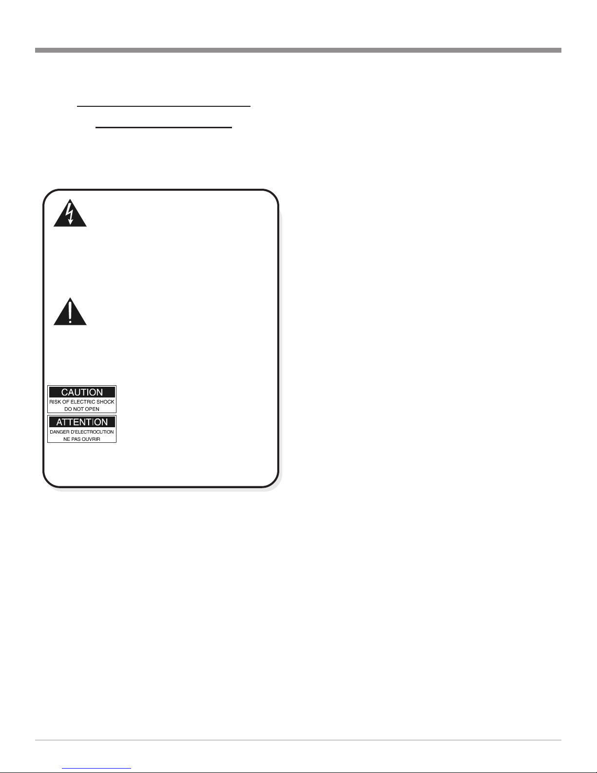
The lightning flash with arrowhead, within an equilateral
triangle, is intended to alert the user to the presence of
uninsulated dangerous voltage within the products
enclosure that may be of sufficient magnitude to consti-
tute a risk of electric shock to persons.
AVIS RISQUE DE CHOC -
NE PAS OUVRIR.
The exclamation point within an equilateral triangle is
intended to alert the user to the presence of important
operating and maintenance servicing) instructions in
the literature accompanying the appliance.
NO USER-SERVICEABLE
PARTS INSIDE. REFER
SERVICING TO
QUALIFIED PERSONNEL.
To prevent the risk of electric shock, do not remove
cover or back). No user serviceable parts inside. Refer
servicing to qualified personnel.
General:
1. Read all the safety and operating instructions, con-
tained in this owners manual, before operating this
equipment.
2. Retain this owners manual for future reference about
safety and operating instructions.
3. Adhere to all warnings and operating instructions.
. Follow all operating and use instructions.
5. Warning: To reduce risk of fire or electrical shock,
do not expose this equipment to rain or moisture.
This unit is capable of producing high sound pres-
sure levels. ontinued exposure to high sound pres-
sure levels can cause permanent hearing impair-
ment or loss. User caution is advised and ear protec-
tion is recommended when playing at high volumes.
6. aution: to prevent electrical shock do not use this
(polarized) plug with an extension cord, receptacle
or other outlet unless the blades can be fully in-
serted to prevent blade exposure.
Attention: pour pevenir les chocs elecriques pas
utiliser cette fiche polarisee avec un prolongateur,
une prise de courant ou un autre sortie de courant,
sauf si les lames peuvent etre inserees afond ans en
laisser aucune partie a decouvert.
7. For added protection for this product during a lightning
storm, or when it is left unattended and unused for long
periods of time, unplug it from the wall outlet. This
will prevent damage to the product due to lightning or
power line surges.
8. Do not use attachments not recommended in this
owners manual as they may cause hazards.
Installation:
9. Locate the equipment for proper ventilation. For ex-
ample, the equipment should not be placed on a bed,
sofa, rug, or similar surface that may block ventilation
openings; or, placed in a built-in installation, such as a
bookcase or cabinet, that may impede the flow of air
through the ventilation openings.
10. Locate the equipment away from heat sources such as
radiators, heat registers, stoves, or other appliance(s)
(including amplifiers) that produce heat.
11. Mount the equipment in a wall or cabinet only as de-
scribed in this owners manual.
12. Do not use this equipment near water; for example,
near a bathtub, washbowl, kitchen sink, laundry tub, in
a wet basement or near a swimming pool, etc.
13. Do not place this product on an unstable cart, stand,
tripod, bracket, or table. The equipment may fall, caus-
ing serious injury to a person, and serious damage to
the product.
onnection:
1 . Connect this equipment only to the type of AC power
source as marked on the unit.
15. Route AC power cords so that they are not likely to be
walked on or pinched by items placed upon or against
them, paying particular attention to cords at plugs, con-
venience receptacles, and the point where they exit
from the instrument.
16. Do not defeat the inherent design features of the polar-
ized plug. Non-polarized line cord adapters will defeat
the safety provided by the polarized AC plug. If the
plug should fail to fit, contact your electrician to re-
place your obsolete outlet. Do not defeat the safety
purpose of the grounding-type plug.

4
·24 Bit DSP Processing
The Motorola 2 Bit Digital Signal Processors decode the
back channel information from specially encoded Digital
5.1 sound tracks.
·20 Bit onversion
Two 20 bit stereo digital to analog, (D/A) converters are
used to reproduce the back channel information, and one
20 bit stereo analog to digital, (A/D) converter is for input
signal from the analog inputs.
·Automatic Expansion Mode
The MSE1 automatically switches expansion modes when
receiving specially encoded Digital 5.1 sound tracks (re-
quires connections to the McIntosh MX132 A/V Control
Center). Expand nomenclature illuminates to show which
decoding mode is in use.
·LED Output Format / Delay / Volume Indicators
The MSE1 includes four LEDs on the Front Panel to indi-
cate status of the output signal format. In addition, there is
a two digit LED indicator that shows the Trim Volume,
Time Delay and Channel Level during surround level cali-
bration.
·Adjustable hannel Time Delays
Signals to the back Surround channels can be time delayed.
This feature can be used to correct the different listening
distances from the back surround speaker(s) and the pri-
mary listening location.
·Built-In System Level alibration Generator
A built-in test signal generator can be switched manually or
automatically through all surround channels for surround
level calibration. The levels can be adjusted plus or minus
6dB.
·Automatic Input Level ontrol
The Analog Input includes a special circuit which protects
against accidental input signal overdrive.
Safety Instructions cont, Introduction and Performance Features
Introduction
The McIntosh MSE1 is a precision Surround Expander
which will reproduce the back channels of specially en-
coded 5.1 digital sound tracks with ultimate fidelity and
sonic purity. The MSE1 has many valuable and useful fea-
tures that will enhance your home theater listening experi-
ence.
Performance Features
17. Do not overload wall outlets, extension cords or inte-
gral convenience receptacles as this can result in a risk
of fire or electric shock.
are of Equipment:
18. Clean the instrument by dusting with a dry cloth. Un-
plug this equipment from the wall outlet and clean the
panel with a cloth moistened with a window cleaner.
Do not use liquid cleaners or aerosol cleaners.
19. Do not permit objects or liquids of any kind to be
pushed, spilled and/or fall into the equipment through
enclosure openings.
20. Unplug the power cord from the AC power outlet
when left unused for a long period of time.
Repair of Equipment:
21. Unplug this equipment from the wall outlet and refer
servicing to a qualified service personnel under the fol-
lowing conditions:
A. The AC power cord or the plug has been damaged.
B. Objects have fallen, or liquid has been spilled into
the equipment.
C. The equipment has been exposed to rain or water.
D. The equipment does not operate normally by fol-
lowing the operating instructions contained within
this owners manual. Adjust only those controls
that are covered by the operating instructions, as an
improper adjustment of other controls may result
in damage and will often require extensive work by
a qualified technician to restore the product to its
normal operation.
E. The equipment has been dropped or damaged in any
way.
F. The equipment exhibits a distinct change in perfor-
mance - this indicates a need for service.
22. Do not attempt to service beyond that described in the
operating instructions. All other service should be re-
ferred to qualified service personnel.
23. When replacement parts are required, be sure the ser-
vice technician has used replacement parts specified by
McIntosh or have the same characteristics as the origi-
nal part. Unauthorized substitutions may result in fire,
electric shock, or other hazards.
2 . Upon completion of any service or repairs to this prod-
uct, ask the service technician to perform safety checks
to determine that the product is in proper operating
condition.

5
Dimensions
The following dimensions can assist in determining the
best location for your MSE1. There is additional informa-
tion on the next page pertaining to installing the MSE1 into
cabinets.
Dimensions
17-1/2"
44.45cm
2-3/4"
7.00cm
4-3/16"
10.60cm
14-5/8"
37.1cm
15-11/16"
39.90cm
3/16"
0.48cm 2-15/16"
7.47cm
11-9/16"
29.36cm 1"
2.54cm
13-1/4"
33.65cm
17"
43.18cm
Front View of the MSE1
Rear View of the MSE1
Side View of the MSE1
3-9/16"
9.00cm
13/16"
2.06cm

6
Installation
The MSE1 can be placed upright on a table or shelf, stand-
ing on its four feet. It also can be custom installed in a
piece of furniture or cabinet of your choice. The required
panel cutout, ventilation cutout and unit dimensions are
shown.
Always provide adequate ventilation for your MSE1.
Cool operation ensures the longest possible operating life
for any electronic instrument. Do not install the MSE1 di-
rectly above a heat generating component such as a high
powered amplifier. If all the components are installed in a
single cabinet, a quiet running ventilation fan can be a defi-
nite asset in maintaining all the system components at the
coolest possible operating temperature.
A custom cabi-
net installation
should provide the
following minimum
spacing dimensions
for cool operation.
Allow at least 2
inches (5.08 cm)
above the top, 2
inches (5.08cm) be-
low the bottom and
1 inch (2.5 cm) on
each side of the
Surround Expander,
so that airflow is
not obstructed. Al-
low 20 inches (50.8
cm) depth behind
the front panel. Al-
low 1 inch (2.5
cm) in front of the
mounting panel for
clearance. Be sure
to cut out a ventila-
tion hole in the
mounting shelf ac-
cording to the di-
mensions in the
drawing.
Installation
3-
1/16
"
7.80cm
17-
1/16
"
43.34cm
Cutout Opening for Custom Mounting
MSE1 Front Panel
Custom Cabinet Cutout
11-
1/2
"
29.20cm
9"
22.90cm
13-
1/4
"
33.70cm
2
-1/8
"
5.4cm
Cutout Opening
for Ventilation
Cutout Opening for Ventilation
Support
Shelf
Cabinet
Front
Panel
Chassis
Spacers
MSE1 Side View
in Custom Cabinet
MSE1 Bottom View
in Custom Cabinet
1
"
2.54cm

7
Rear Panel Switches and Connections
BACK2 OUTPUTS provide
the audio output signals to
the power amplifier inputs
for the Left and Right Ba k
Surround Loudspeakers
SURRound Outputs
provide the Left and
Right Surround Sig-
nals to the power am-
plifier driving the
Surround
Louspeakers
AUTOmati swit hes the
built-in alibration test
signal to ea h of the Sur-
round Loudspeakers in 2
se ond intervals on a on-
tinuous basis. MANual
system alibration requires
the manual sele tion of
Surround Loudspeakers
SPEAKER SETTINGS
swit hes allow the sele tion
of one or two Ba k Surround
Louspeakers, their frequen y
response apability and
whether or not an optional
Se ondary Subwoofer is used
in the system
Conne t the MSE1
power ord to a live AC
outlet. Refer to informa-
tion on the ba k panel of
the MSE1 to determine
the orre t voltage
POWER CONTROL IN
ja k a epts a turn-on sig-
nal from a M Intosh Con-
trol Center. The POWER
CONTROL OUT ja k
sends the turn-on signal to
another M Intosh produ t
DATA IN ja k re eives ontrol
data from a M Intosh A/V Con-
trol Center and the DATA OUT
ja k provides the ontrol data
for the next M Intosh Compo-
nent
The SUBWOOFer OUT-
PUTS feed an audio signal to
the input on a power ampli-
fier for the optional se ond-
ary Subwoofer
BACK1 OUTPUT provides
the audio output signal to the
power amplifier input for the
Ba k Surround Loudspeaker
ANALOG INPUT re eives
Left and Right Surround
Signals from the M Intosh
A/V Control Center

8
McIntosh Powered Secondary Subwoofer
(Optional)
McIntosh Five Channel
Power Amplifier
How to Connect with a MX132
Right
Surround
Left
Surround
®
®
The following connection instructions and illustrations
cover the addition of the McIntosh MSE1 Surround Ex-
pander, McIntosh Back Surround Power Amplifier and op-
tional secondary McIntosh Power Subwoofer into an exist-
ing MX132 Home Theater System. For additional connec-
tion information, please refer to the owners manuals for
the particular components that make up your system.
1. Connect a Power Control Cable from the MX132
Power Control A jack to the POWER CONTROL IN
jack of the McIntosh MSE1 Surround Expander.
2. Connect a Power Control Cable from the POWER
CONTROL OUT jack of the McIntosh MSE1 Sur-
round Expander to the Power Control In jack of the
McIntosh Back Surround Power Amplifier.
3. Connect a Power Control Cable from the Power Con-
trol Out jack of the McIntosh Five Channel Power Am-
plifier to the Power Control In jack of the McIntosh
Powered Subwoofer.
. Connect a Data cable from the MX132 Sum A Data Out
Port to the DATA IN of a jack of the McIntosh MSE1
Surround Expander.
5. Connect cables from the MX132 Zone A Surround Out-
puts to the ANALOG Inputs of the McIntosh MSE1
Surround Expander.
6. Temporarily disconnect the male end of the 25 conduc-
tor DB25 cable from the McIntosh Five Channel
Power Amplifier. Locate and remove (cut out) pins 5,
6, 18 and 19 from the male connector end of the DB25
cable. Reconnect the now modified male end of the
DB25 cable to the McIntosh Five Channel Power Am-
plifier.
Note: The above step is necessary, as the Left and Right
Surround Channels receive additional sound processing
in the MSE1 Surround E pander. The ne t step connects
the MSE1 Surround Outputs to the McIntosh Five
Channel Power Amplifier using the audio connection
cables. If your system consists of
a McIntosh Si Channel Power
Amplifier the same above step
must also be performed.
7. Connect cables from the McIntosh
MSE1 Surround Expander
SURRound Outputs to the Sur-
round Inputs of the McIntosh Five
Channel Power Amplifier.
8. Connect cables from the McIntosh
MSE1 Surround Expander
BACK2 Outputs to the Inputs of
the McIntosh Surround Power
Amplifier.
Note: The MSE1 also has a BACK1 Output that provides a
single Surround Back Channel that may be used in
place of the BACK2 Output.
9. Connect the loudspeaker hookup cables to the output
terminals of the McIntosh Surround Power Amplifier.
10. Plug the MSE1 AC power cord into a live AC outlet.

9
McIntosh MX132
McIntosh Back Surround
Power Amplifier
How to Connect with a MX132
To AC Outlet
Right Back Surround
Loudspeaker
4 ohm
123456789
1
2345678
9
1
2345678
9
1
2345678
9
1
2345678
9
1
2345678
9
1
2345678
9
1
2345678
9
1
2345678
9
1
2345678
9
1
2345678
9
123456789
123456789
1
2345678
9
1
2345678
9
1
2345678
9
1
2345678
9
1
2345678
9
1
2345678
9
1
2345678
9
1
2345678
9
1
2345678
9
1
2345678
9
123456789
Left Back Surround
Loudspeaker
4 ohm
Left and Right
Surround
Refer to step 6 and note
on previous page
¿
¯

1
McIntosh Powered Secondary Subwoofer
(Optional)
How to Connect with a MX130/C39 and MSD4/
MAC-3
McIntosh Five Channel
Power Amplifier
Right
Surround
Left
Surround
®
®
The following connection instructions and illustrations
cover the addition of the McIntosh MSE1 Surround Ex-
pander, Back Surround Power Amplifier and optional sec-
ondary Power Subwoofer into an existing McIntosh Home
Theater System. For additional connection information,
please refer to the owners manuals for the particular com-
ponents that make up your system.
1. Connect a Power Control Cable from the MX130/C39
Power Control (Area A) jack to the Power Control In
jack of the MSD /MAC-3.
2. Connect a Power Control Cable from the MSD /MAC-
3 Power Control Out to the POWER CONTROL IN
jack of the McIntosh MSE1.
3. Connect a Power Control Cable from the POWER
CONTROL OUT jack of the McIntosh MSE1 Sur-
round Expander to the Power Control In jack of the
Back Surround Power Amplifier.
. Connect a Power Control Cable from the Power Con-
trol Out jack of the five channel power amplifier to the
Power Control In jack of the Powered Subwoofer.
5. Connect a Data cable from the MX130/C39 Sum Data
(Area A) Out Port to the Data In jack of the MSD /
MAC-3.
6. Connect a Data cable from the MSD /MAC-3 Data Out
Port to the DATA IN jack of the McIntosh MSE1 Sur-
round Expander.
7. Connect cables from the MX130 Area A Surround Out-
puts to the ANALOG Inputs of the McIntosh MSE1
Surround Expander.
8. Temporarily disconnect the male end of the 25 conduc-
tor DB25 cable from the McIntosh Five Channel
Power Amplifier. Locate and remove (cut out) pins 5,
6, 18 and 19 from the male connector end of the DB25
cable. Reconnect the now modified male end of the
DB25 cable to the five channel power amplifier.
Note: The above step is necessary, as
the Left and Right Surround
Channels receive additional
sound processing in the MSE1
Surround E pander. The ne t
step connects the MSE1
Surround Outputs to the five
channel power amplifier using
the audio connection cables. If
your system consists of a si
channel power amplifier the
same above step must also be
performed.
9. Connect cables from the McIntosh
MSE1 Surround Expander
SURRound Outputs to the Surround Inputs of the five
channel power amplifier.
10. Connect cables from the McIntosh MSE1 Surround
Expander BACK2 Outputs to the Inputs of the sur-
round power amplifier.
Note: The MSE1 also has a BACK1 Output that provides a
single Surround Back Channel that may be used in
place of the BACK2 Output.
11. Connect the loudspeaker hookup cables to the output
terminals of the surround power amplifier.
12. Plug the MSE1 AC power cord into a live AC outlet.

11
McIntosh MSD4/MAC-3
McIntosh MX13 /C39
How to Connect with a MX130/C39 and MSD4/MAC-3
McIntosh Back Surround
Power Amplifier
To AC Outlet
Right Back Surround
Loudspeaker
4 ohm
123456789
1
2345678
9
1
2345678
9
1
2345678
9
1
2345678
9
1
2345678
9
1
2345678
9
1
2345678
9
1
2345678
9
1
2345678
9
1
2345678
9
123456789
123456789
1
2345678
9
1
2345678
9
1
2345678
9
1
2345678
9
1
2345678
9
1
2345678
9
1
2345678
9
1
2345678
9
1
2345678
9
1
2345678
9
123456789
Left Back Surround
Loudspeaker
4 ohm
Left and Right
Surround
Refer to step 8
and note on pre-
vious page
¿
¯

12
McIntosh Powered Secondary Subwoofer
(Optional)
How to Connect with a MSD4/MAC-3
The following connection instructions and illustrations
cover the addition of the McIntosh MSE1 Surround Ex-
pander, Back Surround Power Amplifier and optional sec-
ondary Power Subwoofer into an existing MSD /MAC-3
Home Theater System. For additional connection informa-
tion, please refer to the owners manuals for the particular
components that make up your system.
1. Connect a Power Control Cable from the MSD /MAC-
3 Power Control Out jack to the POWER CONTROL
IN jack of the McIntosh MSE1 Surround Expander.
2. Connect a Power Control Cable from the POWER
CONTROL OUT jack of the McIntosh MSE1 Sur-
round Expander to the Power Control In jack of the
back surround power amplifier.
3. Connect a Power Control Cable from the Power Con-
trol Out jack of the back surround power amplifier to
the Power Control In jack of the five channel power
amplifier.
Note: A si channel power amplifier may also be used in place
of the five channel amplifier.
. Connect a Power Control Cable from the Power Con-
trol Out jack of the five channel power amplifier to the
Power Control In jack of the powered subwoofer.
5. Connect a Data cable from the MSD /MAC-3 Data Out
Port to the DATA IN of a jack of the McIntosh MSE1
Surround Expander.
6. Connect cables from the MSD /MAC-3 Surround Out-
puts to the ANALOG INPUTS of the McIntosh MSE1
Surround Expander.
8. Connect cables from the McIntosh MSE1 Surround Ex-
pander SURRound Outputs to the Surround Inputs of
the five channel power amplifier.
9. Connect cables from the McIntosh MSE1 Surround Ex-
pander BACK2 Outputs to the Inputs of the surround
power amplifier.
Note: The MSE1 also has a BACK1 Output that provides a
single Surround Back Channel
that may be used in place of the
BACK2 Output.
10. Connect the loudspeaker hookup
cables to the output terminals of
the surround power amplifier.
11. Plug the MSE1 AC power cord
into a live AC outlet.
McIntosh Five Channel
Power Amplifier
Left
Surround
Right
Surround
®
®

13
McIntosh MSD4/MAC-3
How to Connect with a MSD4/MAC-3
McIntosh Back Surround
Power Amplifier
To AC Outlet
Right Back Surround
Loudspeaker
4 ohm
123456789
1
2345678
9
1
2345678
9
1
2345678
9
1
2345678
9
1
2345678
9
1
2345678
9
1
2345678
9
1
2345678
9
1
2345678
9
1
2345678
9
123456789
123456789
1
2345678
9
1
2345678
9
1
2345678
9
1
2345678
9
1
2345678
9
1
2345678
9
1
2345678
9
1
2345678
9
1
2345678
9
1
2345678
9
123456789
Left Back Surround
Loudspeaker
4 ohm
Left and Right
Surround
¿

14
CHANNEL STATUS LED display
indi ates whi h hannels are a tive,
depending on the in oming signal;
LS (Left Surround), BS (Ba k Sur-
round), RS (Right Surround) and
SUB (Subwoofer)
Indi ates when
the MSE1 is in
the Surround
EXPAND Mode
DELAY/TRIM Indi a-
tor shows the Trim
Volume Level, Chan-
nel Level and Time
Delay
AUTO MODE allows for
automati swit hing and
indi ating of the Surround
Expansion Mode
Front Panel Controls, Push-Buttons, Switches and Displays
SYS CAL push-button
a tivates the internal test
signal generator for sur-
round hannel level ali-
bration
POWER swit h
turns all power
ompletely ON
or OFF
TRIM push-button a ti-
vates the Volume Level
Push-buttons for all the
Surround Channels
LEVEL q and p push-
buttons allow for volume
adjustment of all the Sur-
round Loudspeakers
STANDBY/ON
push-button turns
the MSE1 on and
off, and an reset
all the MSE1 mi-
ropro essors
MANUAL MODE
allows for manual
swit hing of the
Surround Expan-
sion Mode
Indi ates when AC
Power is applied to
the MSE1
DELAY push-button
a tivates the Time De-
lay Adjusting Pro ess
for the Ba k Surround
Loudspeaker(s)

15
Speaker Settings
Speaker Settings
The McIntosh MSE1 Rear Panel Speaker Settings are for
selecting the number of Back Surround Loudspeaker(s), the
size of all the Surround Loudspeakers and if an optional
secondary Subwoofer is used. Refer to figures 1, 2 and 3.
Back 1 and 2 Selection
The MSE1 Surround Expander may be operated with either
a single Center Back Surround Loudspeaker or a Left and
Right Back Surround Loudspeakers. Select the either the
BACK 1 or 2 Switch Position to match your system.
Note: If your system is using a Left and Right Back Surround
Loudspeakers the actual signal sent to them is the same
and is reduced in level by 3dB over a single Center
Back Surround Loudspeaker Setup.
Back Surround Speaker Size
When the Back Surround Loudspeaker(s) cover the full fre-
quency range down to 20Hz, set the switch to LARGE. If
the Back Surround Loudspeakers cover the frequency
range only down to 80Hz, set the switch to SMALL. The
NONE Speaker Switch position should be selected when
no Back Surround Loudspeakers are connected or when the
Surround Expansion Processing is bypassed.
Figure 1
Figure 3
Figure 2
Surround Speaker Size
When the Left and Right Surround Loudspeakers cover the
full frequency range down to 20Hz, set the switch to
LARGE. If the Left and Right Surround Loudspeakers
cover the frequency range only down to 80Hz, set the
switch to SMALL.
Subwoofer Speaker
Set the SUBWOOF switch to ON whenever the Optional
Secondary Subwoofer is used in the system. In this mode,
the Low Frequencies are sent to the subwoofer when either
the Left and Right Surround or the Back Surround Loud-
speaker SPEAKER Switches are set to SMALL. If both
Side and Back Surround Loudspeakers SPEAKER Switch
setting is LARGE, all the low frequencies will be redi-
rected to the Surround Loudspeakers and no sound will be
heard from the Subwoofer.

16
The McIntosh MSE1 Surround Expander provides auto-
matic expansion of Surround Enhancement Information
contained in movie sound tracks. This additional informa-
tion is encoded in the surround channels by using a Matrix
Method. The MSE1 converts the incoming analog surround
channels into digital signals, processes the signals digitally,
then convert it back to analog signals consisting of the Left
Surround, Right Surround and Back Surround Channels.
In order to assure the best possible Surround Expansion,
it is extremely important that both Surround Channel Sig-
nals going into the MSE1 have as close as possible the
same level and time delay characteristics. Adjust the levels
and delay settings for the surround channels of your Home
Theater System for the same surround channel loudspeaker
level and the time delay settings, refer to the Owners
Manual supplied with McIntosh A/V Control Center and/or
Surround Decoder. If there are differences in the settings
between the surround channels, then pick the average be-
tween the two suround channels settings and use that aver-
age for both Surround Channels.
Delay and Level calibration procedures are made rela-
tive to the primary listening area. The ideal listening area is
defined as facing directly toward and centered between the
front speakers, in line with the left and right surround
speakers and the back surround louspeaker(s) behind the
primary listening area. Refer to the figures and 5.
Back Surround Speaker Delay
If the back surround speakers are located closer to the lis-
tening area than the surround speakers, their sound will
reach the listener before the sound from the surround
Surround Calibration
speakers. This difference in sound arrival times can de-
grade the listening perception of some sound tracks. The
MSE1 allows you to adjust the back surround speaker time
delay to correct for this difference so the sound from the
back surround speakers reaches the listening area at the
same time as sound from the left and right surround loud-
speakers. Refer to figure 6.
Note: The MSE1 surround delay can be adjusted from 0 to
5ms. Each millisecond delay corresponds appro imately
to 1 foot in distance.
The first time you press the DELAY push-button the DE-
LAY/TRIM display will indicate 0, which the factory de-
fault setting. This would correspond to the delay setting
you have just performed on your McIntosh A/V Control
Center and/or Surround Decoder for the Left and Right
Surround Loudspeakers.
1. Measure the distance from the listening area to the
Back Surround Loudspeaker(s). If the Back Surround
Loudspeakers are closer than the average distance from
the listening area to the Left and Right Surround
Louspeakers you should adjust the delay to correspond
to the difference in feet.
2. Press the DELAY push-button to start delay calibration
procedure.
3. Adjust the LEVEL p and q push-buttons until the
DELAY/TRIM display reads a number that is the same
as the number of feet measured in Step 1.
Note: The table on the ne t page may be used to record your
Delay Calibration Settings.
. Press the DELAY push-button a second time to exit the
delay procedure.
Figure 4
Figure 5

17
Surround Calibration
E ample: If your Back Surround Loudspeaker(s) are 2 feet
closer to the listening area than the Left and Right
Surround Loudspeakers, set the center delay to 2.
Surround Speaker Levels
The MSE1 includes a built-in test signal generator to per-
form System Level Calibration. A properly calibrated Sur-
round Sound System should have all channel levels ad-
justed for similar volume in the listening area. This ensures
that multi-channel sound tracks will be reproduced with
optimum realism. Individual channel levels from an actual
sound track usually change widely on a continuous basis.
Proper System Calibration sets all channels to the correct
starting reference level. Refer to figure 6.
Note: All System Level Calibrations are retained in permanent
memory and will change only if calibration is
performed again. A sound level pressure meter may be
used to obtain a more accurate Level Calibration.
Automatic System Calibration
1. Set the rear panel SYSTEM CALIBRATION switch to
AUTO.
2. Press the SYS CAL push-button once to start System
Calibration. You will hear the test signal from the Left
Surround Loudspeaker for 2 seconds. The test signal
will then cycle clockwise through all Surround Chan-
nels and optional Secondary Subwoofer continuously
in 2 second intervals. The MSE1 DELAY/TRIM dis-
play will read 0 for each channel before any adjust-
ments are performed.
Note: The MSE1 Front Panel DELAY/TRIM Display will read
0 for each channel before any adjustments are
Figure 6
performed and the OUTPUT FORMAT LEDs will light
to indicate which channel is reproducing the test signal.
3. While seated in the listening area, note the volume lev-
els of the test signal from each of the channels as the
test signal switches. If you determine that the test sig-
nal volume is louder or softer in any of the channels,
the levels should be adjusted so you hear essentially
the same test signal volume from all of the channels.
The Left Surround Loudspeaker can serve as a refer-
ence.
. Make channel level calibration adjustments by using
the LEVEL p and q push-buttons, the DELAY/VOL-
UME display instantly changes to indicate the calibra-
tion level change in dB. If the level is increased, the
display shows plus numbers, and if decreased shows
minus numbers. Calibration levels can be adjusted over
a range of ±6dB. If an adjustment is made on a chan-
nel, there is an additional 2 second time interval on that
channel before the system switches the test signal to
the next channel.
5. When the test signal switches to succeeding channels,
repeat the level calibration process until the test signal
volume levels of all the channels are the same.
6. The calibration channel cycling mode can be repeated
as often as necessary until you are satisfied that the
volume levels of the test signal are the same from all
channels.
Note: A Surround Level Calibration Table, located on the ne t
page, is provided to record your settings.
7. Exit the System Calibration mode by pressing the SYS
CAL push-button a second time.
Manual System Calibration
1. Set the rear panel SYSTEM CALIBRATE switch to
MAN.
2. Press the SYS CAL push-button once to start System
Calibration, you will hear the test signal from the Left
Surround Loudspeaker. It will stay in that channel until
the SYS CAL push-button is pressed again. The second
time SYS CAL push-button is pressed the sound will
Surround Delay Calibration
Surround Channel Default Setting New Setting
Left
Right
Back

18
Surround Calibration, cont
Surround LevelCalibration
Surround Channel Default Setting New Setting
Left
Right
Back Left
Back Right
Back Center
Secondary
Subwoofer
switch to the Back Surround Loudspeaker(s) followed
by the Left Surround and Subwoofer. The MSE1 DE-
LAY/TRIM display will read 0 for each channel be-
fore any adjustments are performed.
Note: The MSE1 Front Panel DELAY/TRIM Display will read
0 for each channel before any adjustments are
performed and the OUTPUT FORMAT LEDs will light
to indicate which channel is reproducing the test signal.
3. While seated in the listening area, note the volume lev-
els of the test signal from each of the channels as the
test signal switches. If you determine that the test sig-
nal volume is louder or softer in any of the channels,
the levels should be adjusted so you hear essentially the
same test signal volume from all of the channels. The
Left Surround Loudspeaker can serve as a reference.
. Make channel level calibration adjustments by using the
LEVEL p and q push-buttons, the DELAY/VOL-
UME display instantly changes to indicate the calibra-
tion level change in dB. If the level is increased, the
display shows plus numbers, and if decreased shows
minus numbers. Calibration levels can be adjusted over
a range of ±6dB. If an adjustment is made on a channel,
there is an additional 2 second time interval on that
channel before the system switches the test signal to
the next channel.
5. When the test signal switches to succeeding channels,
repeat the level calibration process until the test signal
volume levels of all the channels are the same.
6. The calibration channel cycling mode can be repeated
as often as necessary until you are satisfied that the vol-
ume levels of the test signal are the same from all chan-
nels.
Note: A Surround Level Calibration Table to the right is
provided to record your settings.
7. Exit the System Calibration mode by pressing the SYS
CAL push-button a second time.
Figure 6

19
ower On
Press the POWER Switch to ON. The Red LED, to the
right of the POWER Switch, lights to indicate the MSE1 is
in Standby Mode. To turn ON the MSE1 press the
STANDBY/ON push-button. Refer to figure 7.
Note: The POWER Switch is only intended to be switched
OFF when the MSE1 Surround E pander is not used for
e tended periods of time, like while away on vacation.
During normal operation, the POWER Switch should
stay in the ON position. Press the STANDBY/ON Push-
button for turning the MSE1 ON and OFF. When the
Power Control Cable is connected to a McIntosh A/V
Control Center or Surround Decoder, the MSE1
Surround E pander will automatically switch ON and
OFF.
Reset of Microprocessors
In the event that the controls of the MSE1 stop functioning,
there is a user reset function built in. While the MSE1 is
On, press and hold in the STANDBY/ON/RESET push-
button for five seconds, this will reset the MSE1s micro-
processors. In rare circumstances the pushing of the
STANDBY/ON/RESET push-button for five seconds might
not reset the MSE1s microprocessors. If that were to occur,
then place the POWER Switch to the OFF position for two
to five minutes and then back ON again.
Note: The above condition is usually caused by either
interruptions in AC power and/or major changes in
voltage.
How to Operate the MSE1
Figure 7
Auto Mode
Pressing the AUTO MODE push-button places the MSE1
in the Automatic Surround Expansion Mode of operation
and the LED above the push-button lights. When the MSE1
receives, via its data port, the correct control signal the
MSE1 will automatically switch into the Surround Expan-
sion Mode and the Back Surround Loudspeaker(s) will re-
produce the added sound track information. If there is no
control signal present, the Surround Expansion Mode will
switch Off and no sound will be heard from the Back Sur-
round Loudspeaker(s). Refer to figure 8.
Note: Currently only the MX132 has the ability to pass on that
control signal to the MSE1. The MX132 continuously monitors
the digital signal bitstream from its rear panel optical or coa ial
digital inputs. The e pander will only be engaged when specially
encoded 5.1 sound tracks are recognized by the MX132. If the
bitstream changes, the MSE1 processor is notified of the change,
which lights the EXPAND indicator and the appropriate
OUTPUT FORMAT LEDs.
Manual Mode
Pressing the MANUAL MODE push-button places the
MSE1 in the Surround Expansion Mode of operation and
the LED above the push-button lights. The MSE1 will con-
tinuously operate in the Surround Expansion Mode and
provide surround expansion from any 5.1 or Pro-Logic
sound track material that are reproduced with decorrelated
surround channels. The MSE1 lights the EXPAND indica-
tor and the appropriate OUTPUT FORMAT LEDs. Refer
to figure 8.
Sys Cal
A built-in test signal generator can be switched manually or
automatically through all surround channels for level cali-
bration. The levels can be adjusted ±6dB. The MSE1 has a
super precision volume trim control, and its tracking accu-
racy for all four channels is within one quarter of a dB
throughout its range. Refer to figure 6.
Figure 8

2
How to Operate the MSE1, cont
Delay
The Back Surround channel has an adjustable time delay.
This compensates for speakers that are placed at varying
distances, and insures that sound from all speakers arrive at
the listening position at the same time. The delay time is
adjustable from 0mS to 5mS in 1ms steps, which is a dis-
tance approximately zero to 5 feet. Refer to figure 8.
Level p and q
The push-buttons allow the up and down adjustment of
Back Surround Channel Delay, the Surround Channels and
Subwoofer Levels during the calibration process. They
also allow all the Surround Loudspeaker Levels to change
while listening. Refer to figure 8.
Note: The TRIM push-button needs to be pressed first, to
activate the LEVEL push-buttons.
Trim
Pressing the TRIM push-button allows the MSE1 Surround
Loudspeakers Levels to go up and down ±6dB, when used
with the LEVEL p and q push-buttons. The LED above
the TRIM push-button lights to indicate that the Trim func-
tion is active. Refer to figure 8.
Figure 8
Table of contents
Other McIntosh Recording Equipment manuals

McIntosh
McIntosh MCD1000 User manual

McIntosh
McIntosh C45 User manual

McIntosh
McIntosh C41 User manual

McIntosh
McIntosh C8 - SCHEMATICS User manual

McIntosh
McIntosh C42 User manual

McIntosh
McIntosh C36 User manual

McIntosh
McIntosh C45 User manual

McIntosh
McIntosh C40 User manual

McIntosh
McIntosh C45 User manual

McIntosh
McIntosh MCD1000 User manual
Popular Recording Equipment manuals by other brands

Lutron Electronics
Lutron Electronics Grafik Eye GRX-TVI Installation and operation instructions

M2SYNTH
M2SYNTH Ring Modulator 151 Assembly instructions

Pyle Pro
Pyle Pro PSPVC4 manual

Kvaser
Kvaser Ethercan HS user guide

Siemens
Siemens N148/22 Operating and mounting instructions

Tubbutec
Tubbutec OrganDonor installation manual