Shure ANI4IN Series User manual

ANI4IN
Audio Network Interface
Complete user guide for the ANI4IN. Includes system diagrams, specifications, installation instructions, command strings, and more.
Version: 2.3 (2022-E)

Shure Incorporated
2/28
Table of Contents
ANI4IN Audio Network Interface 3
Overview 3
General Description 3
Model Variations 3
Hardware and Installation 3
Hardware 3
Power Over Ethernet (PoE) 5
Installation and Rack Mounting 5
Reset 8
Software Reset Options 8
Levels and Metering 8
Adjusting Input Levels 8
Adjusting Output Levels 9
Metering Options (Pre-fader and Post-fader) 9
Mute Sync 10
Signal Flow and Connections 10
Setting up the Audio Network 10
Connections and Signal Flow 13
Summing 14
Example Scenario 14
Parametric Equalizer 15
Setting Filter Parameters 15
Equalizer Applications 16
Software Installation, Management, and Security 17
Software Installation and Device Discovery 17
Accessing the Web Application 17
Accessing the Web Application without the Discovery App1
8
Channel Utilities 18
Custom Presets 18
Event Log 19
Firmware Updates 19
Firmware Release Requirements 20
Encryption 20
Using Command Strings 21
Logic Applications 21
Networking and Dante 21
Digital Audio Networking 21
Switch and Cable Recommendations for Dante Network
ing 22
Dante Transmit Flows 22
Compatibility with Dante Domain Manager 22
QoS (Quality of Service) Settings 23
Packet Bridge 23
Specifications 24
IP Ports and Protocols 26
Accessories 26
Furnished Accessories 27
Optional Accessories and Replacement Parts 27
Important Product Information 27
Information to the user 27
Contact Customer Support 28

Shure Incorporated
3/28
ANI4IN
Audio Network Interface
Overview
General Description
The Shure ANI4IN Audio Network Interface converts 4 analog audio channels into independent digital audio channels on a
Dante network. Microphone, auxiliary, and line-level devices are supported, with adjustable gain and +48V phantom power for
each channel. In networked conferencing systems, the Audio Network Interface provides a simple way to connect analog
equipment onto the audio network, such as wireless microphones. The web application controls signal routing and channel set
tings from any computer connected to the same network.
Model Variations
ANI4IN-XLR: Four XLR inputs (balanced audio only)
ANI4IN-BLOCK: Four 6-pin block connector inputs (balanced audio and logic connections)
Hardware and Installation
Hardware
Block Connector Model:
XLR Model:
™

Shure Incorporated
4/28
①Input Signal Clip Indicators
Each indicator corresponds to a single input channel. If the LED turns red, attenuate the level from the source device to
prevent clipping at the input stage. Analog and digital gain adjustments are made through the web application.
LED State Audio Signal Level
Off less than -60 dBFS
Green -59 dBFS to -24 dBFS
Yellow -23 dBFS to -1 dBFS
Red 0 dBFS or more
②Audio and Logic Inputs
Note: Logic connections are only featured on the block connector version
Block Inputs: Each input receives balanced audio and logic signals. Pin assignments are as follows:
Audio +
Audio -
Audio ground
switch Logic Mute (sent from microphone)
led Logic LED (received by microphone)
gnd Logic ground
XLR Inputs: Each input receives a balanced audio signal. Pin assignments are as follows:
1Ground

Shure Incorporated
5/28
•
•
2Positive
3Negative
③Chassis Ground Screw
Provides an optional connection for microphone shield wire to chassis ground
Note: only applies to block connector version
④LED Indicators
Power: Power over Ethernet (PoE) present
Note: Use a PoE injector if your network switch does not supply PoE.
Network: Network connection active
Network Audio: Dante audio present on the network
Note: Error details are available in the event log in the web application.
Encryption: Not currently supported
LED Status Activity
Off No active signal
Green Device is operating successfully
Red Error has occurred. See event log for details.
⑤Dante Network Port
Connects to a network switch to send Dante audio, while receiving Power over Ethernet (PoE) and data from the control
software. See the Dante and networking section for additional information.
⑥Reset Button
Resets the device settings back to the factory default.
Power Over Ethernet (PoE)
This device requires PoE to operate. It is compatible with both Class 0 and Class 3 PoE sources.
Power over Ethernet is delivered in one of the following ways:
A network switch that provides PoE
A PoE injector device
Installation and Rack Mounting
Two mounting solutions are available for installing the Audio Network Interface:
CRT1 19" Rack Tray (optional accessory): Supports up to 3 devices; mountable in a rack or under a table
Single-unit Mounting Tray (included accessory): Supports a single device for mounting under a table
Securing the Devices
Use the included screws from the mounting hardware kit to secure the Audio Network Interfaces. Audio Network Interfaces can
be mounted to face either direction. Insert the screws from the bottom in the appropriate holes, according to the following dia
grams:

Shure Incorporated
6/28
1.
2.
Align the holes as shown for securing a single device in the single-unit mounting tray
Align the holes as shown for securing up to 3 devices in the 19" rack tray.
Rack Ear Configuration
A combination of up to 3 Audio Network Interfaces can be mounted in a single 19-inch rack space. The adjustable rack ears
support mounting in a standard equipment rack or underneath a table.
Standard 19" Rack Mount
Align the ears with the mounting holes pointed forward.
Install the 3 screws that hold the ear to the tray as shown.

Shure Incorporated
7/28
1.
2.
1.
2.
3.
Under-Table Mounting
Align the ears with the mounting holes pointed upward.
Install the 3 screws that hold the ear to the tray as shown.
Installing Underneath a Table
Hold the tray in the desired location under a table.
Use a pencil to mark the location of the mounting holes on the table.
Drill 4 holes for the screws. The diameter of the holes in the tray are 7.1 mm.

Shure Incorporated
8/28
4.
5.
1.
2.
3.
4.
Install the components into the tray.
Install with 4 screws to secure the tray underneath the table.
Reset
The reset button is located inside a small hole in the rear panel. Use a paperclip or other small tool to press the button.
There are two hardware reset functions:
Network reset (press button for 4-8 seconds)
Resets all Shure control and audio network IP settings to factory defaults
Full factory reset (press button for longer than 8 seconds)
Restores all network and Designer settings to the factory defaults.
Software Reset Options
To simply revert settings without a complete hardware reset, use one of the following options:
Reboot Device:Power-cycles the device as if it were unplugged from the network. All settings are retained when the device is
rebooted.
Default Settings: To revert audio settings back to the factory configuration (excluding Device Name, IP Settings, and Pass
words), select Load Preset and choose the default settings preset.
Levels and Metering
Adjusting Input Levels
Before you begin, verify that levels from the analog devices with adjustable output levels are operating at nominal levels.
The analog gain adjusts the level of the audio signal before it is converted from analog to digital. It is adjustable in 3 dB incre
ments, with up to 51 dB total gain.
Set the Metering to Pre-fader in the toolbar at the top of the workspace to monitor analog signal levels
Select the analog gain value to open the fader
Match the analog gain setting to the incoming signal level. Use the gain range markers on the fader to apply the appro
priate amount of gain:
Source Level Gain Range
Line (+4 dBu) 0 to +9 dB
Auxiliary (-10 dBV) +9 to +21 dB
Microphone (varies) +21 to +51 dB
The meters should peak between -18 and -9 dB.
Note: Leaving some additional headroom is a recommended to prevent clipping if mobile devices will be plugged into particular channels.

Shure Incorporated
9/28
1.
2.
3.
Adjusting Output Levels
Output levels are controlled by the Digital Gain (dB) fader. Always adjust the input gain (analog) before the output gain (digital).
In most cases, setting the analog gain correctly results in an appropriate output level. Sources that have a quiet signal, such as
a microphone with low sensitivity, may need someDigital Gain (dB) applied. If adjustments to the Digital Gain (dB) fader are re
quired, follow these steps:
Set the Metering to Post-fader in the toolbar at the top of the workspace.
Adjust theDigital Gain (dB) fader as needed.
If using summing, use the Digital Gain (dB) faders to mix the channel levels.
Metering Options (Pre-fader and Post-fader)
There are two modes for monitoring, for input and output signals to be monitored separately.
Pre-Fader (Analog Input Level)
Pre-fader metering displays the signal level before it reaches the digital gain fader, so that input signal levels can be optimized
for each channel. Analog gain adjustments affect the meter when set to pre-fader, but the digital gain adjustments do not.

Shure Incorporated
10/28
•
•
•
•
•
•
•
•
•
•
◦
◦
◦
◦
Important: If the incoming signal is adjustable (wireless microphone systems, for example), make sure it is at the nominal level
before adjusting the analog gain on the Audio Network Interface.
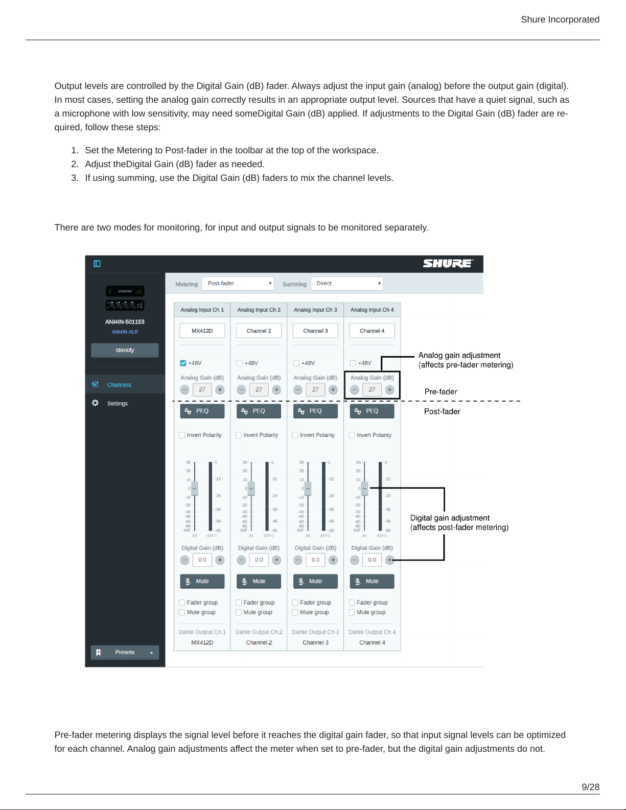
Post-Fader (Digital Output Level)
Post-fader metering displays the signal level at the very end of the signal chain, which includes both the analog and digital
gain. Use this setting to meter the levels that are being sent over the Dante network.
Mute Sync
Mute sync ensures that all connected devices in a conferencing system mute or unmute at the same time and at the correct
point in the signal path. Mute status is synchronized in the devices using logic signals or USB connections.
To use mute sync, make sure logic is enabled on all devices.
Designer's Optimize workflow configures all necessary mute sync settings for you.
Compatible Shure logic devices:
P300 (Also mutes supported soft codecs connected by USB)
ANIUSB-MATRIX (Also mutes supported soft codecs connected by USB)
IntelliMix Room
®software (Also mutes supported soft codecs connected by USB)
MXA910
MXA710
MXA310
Network Mute Button
ANI22-BLOCK
ANI4IN-BLOCK
Logic-enabled MX microphones connected to ANI22-BLOCK or ANI4IN-BLOCK
MX392
MX395-LED
MX396
MX405/410/415
To use mute sync, connect a logic-enabled MX series microphone to an ANI4IN-BLOCK or ANI22-BLOCK.
Note: See microphone guides to learn how to turn on logic on mics.
For help with specific mute sync implementations, see our FAQs.
Signal Flow and Connections
Setting up the Audio Network
Shure networked conferencing systems are comprised of Microflex Advance microphones and network interfaces, which oper
ate entirely on a Dante network. Additional hardware, including network switches, computers, loudspeakers, and audio proces
sors are described in the hardware component index.
Shure components shown in this diagram:
Microflex Advance Microphones
The MXA910 and MXA310 are equipped with Dante outputs, and connect directly to a network switch.

Shure Incorporated
11/28
Audio Network Interfaces
The interfaces are used to connect analog devices such as loudspeakers and analog microphones to the network.
ANI4IN: Converts 4 analog signals (separate XLR and block connector models available) into Dante digital audio signals.
ANI4OUT: Converts 4 channels of Dante audio from the network into analog signals.
This diagram shows the entire signal path through a networked conference system. Signals from the near end and far
end are exchanged through an audio processor connected to a phone system, or through a computer connected to
the internet. Analog microphones connect to the network through the Shure ANI4IN, while loudspeakers connect
through the Shure ANI4OUT.

Shure Incorporated
12/28
This diagram shows Microflex Advance components in context, with two rooms communicating through video codecs.
Controlling Hardware and Audio Over the Network
Audio and hardware settings are managed through a computer connected to the same network.
Shure Hardware and Audio
Each Microflex Advance component has a web application which provides mixing and configuration tools to optimize sound
quality.
Expanded Control for Analog Devices
Analog devices that are connected to the network through a Shure network interface (ANI4IN/ANI4OUT) benefit from additional
remote control: Volume levels, equalization, and signal routing are managed through the web application. For example, adjust
ing loudspeaker volume or muting a wired microphone, which would normally be done from the hardware, can now be con
trolled remotely over the network.
Dante Signal Routing
You can manage signal routing with Dante Controller or Shure Designer software.

Shure Incorporated
13/28
•
•
•
•
Connections and Signal Flow
①MX396 (Dual-element)
In addition to running the audio signals, this boundary microphone features three additional wire leads for logic connec
tions. This allows the switch on the microphone to send a logic mute signal to other equipment on the network, and to re
ceive a logic LED control signal.
②MX392
In addition to running the audio signal, this boundary microphone features three additional wire leads for logic connections.
This allows the switch on the microphone to send a logic mute signal to other equipment on the network, and to receive a
logic LED control signal.
③ULX-D Receiver
Wireless microphones connect to the network interface through the balanced analog outputs on the receiver.
④Network Switch
Provides connectivity between the Dante audio network and the computer that controls signal processing and routing.
⑤Computer
A computer or tablet running the web application provides independent gain control for each connected device.
Input: Analog (4 XLR or Block Connectors)
Each Audio Network Interface has 4 analog inputs with variable analog gain for line, auxiliary, and microphone-level signals.
Examples of devices to connect to the network with the Audio Network Interface:
Wireless microphone systems
Wired installed microphones (logic functions supported by block connector model)
Computers or mobile devices used for presentations
Other playback devices
Output: Dante Digital Audio
Connect the Dante output to a network switch with a network cable. A single network cable delivers all 4 channels of audio onto
the network, and carries Power over Ethernet (PoE) to power the device. Use Dante Controller to route audio channels from
the Audio Network Interface to the appropriate network destination. Any of the signals may be routed to multiple destinations,
to provide local reinforcement while simultaneously delivering audio to the far end.

Shure Incorporated
14/28
Summing
The Audio Network Interface provides channel summing to combine input signals and send them over a single Dante channel.
This makes it possible to send all channels to a device with a limited amount of Dante receiver channels. Mixer functionality
does not change; audio channels are simply sent as one combined signal.
Note: When summing is enabled, a limiter is activated to prevent signal overloading. The limiter never applies to the direct outputs, and only affects the
summed signal.
To enable, select one of the summing options in the toolbar at the top of the mixer in the channels tab.
Example Scenario
A common application that requires summing is a video conference where there are multiple microphones. When a device (a
computer running conferencing software and Dante Virtual Soundcard, for example) only supports 1 or 2 Dante receiver chan
nels, the Audio Network Interface combines the input signals to transmit as a single Dante channel.
①Summed analog audio channels

Shure Incorporated
15/28
•
•
•
•
When the 4 analog audio channels are summed, each of the Dante transmit channels includes all of the input signals.
②Single Dante audio channel
One Dante signal is sent over the network, which contains all 4 summed channels.
③Connection to computer
A computer that is running limited number of Dante channels with Dante Virtual Soundcard, receives all audio on a single
channel. This audio is sent to the far end.
Parametric Equalizer
Maximize audio quality by adjusting the frequency response with the parametric equalizer.
Common equalizer applications:
Improve speech clarity
Reduce noise from HVAC systems or video projectors
Reduce room irregularities
Adjust frequency response for reinforcement systems
Setting Filter Parameters
Adjust filter settings by manipulating the icons in the frequency response graph, or by entering numeric values. Disable a filter
using the check-box next to the filter.
Filter Type
Only the first and last band have selectable filter types.
Parametric: Attenuates or boosts the signal within a customizable frequency range
Low Cut: Rolls off the audio signal below the selected frequency
Low Shelf: Attenuates or boosts the audio signal below the selected frequency
High Cut: Rolls off the audio signal above the selected frequency
High Shelf: Attenuates or boosts the audio signal above the selected frequency
Frequency Select the center frequency of the filter to cut/boost
Gain Adjusts the level for a specific filter (+/- 30 dB)
Q Width Adjusts the range of frequencies affected by the filter. As this value increases, the bandwidth
becomes thinner.

Shure Incorporated
16/28
1.
2.
3.
1.
Equalizer Applications
Conferencing room acoustics vary based on room size, shape, and construction materials. Use the guidelines in following ta
ble.
EQ Application Suggested Settings
Treble boost for improved speech intelligibility Add a high shelf filter to boost frequencies greater than 1
kHz by 3-6 dB
HVAC noise reduction Add a low cut filter to attenuate frequencies below 200 Hz
Reduce flutter echoes and sibilance
Identify the specific frequency range that "excites" the room:
Set a narrow Q value
Increase the gain to between +10 and +15 dB, and
then experiment with frequencies between 1 kHz and
6 kHz to pinpoint the range of flutter echoes or sibi
lance
Reduce the gain at the identified frequency (start be
tween -3 and -6 dB) to minimize the unwanted room
sound
Reduce hollow, resonant room sound
Identify the specific frequency range that "excites" the room:
Set a narrow Q value

Shure Incorporated
17/28
2.
3.
•
•
•
•
1.
2.
EQ Application Suggested Settings
Increase the gain to between +10 and +15 dB, and
then experiment with frequencies between 300 Hz
and 900 Hz to pinpoint the resonant frequency
Reduce the gain at the identified frequency (start be
tween -3 and -6 dB) to minimize the unwanted room
sound
Software Installation, Management, and Security
Software Installation and Device Discovery
The Shure Web Device Discovery application is used to access the web application for a Shure device. The web application
opens in a web browser to provide comprehensive device management. Any computer networked to the device can access the
GUI with this application.
Compatible Browsers:
Chrome
Safari
Firefox
Internet Explorer
Install the Shure device discovery application, available at www.shure.com
Double-click the component to open the interface.
Accessing the Web Application
The Shure Web Server Discovery application finds all Shure devices on the network that feature a web-based GUI. Follow
these steps to install the software and access the web application:
①Install the Shure Discovery application
Download and install the Shure Discovery application from www.shure.com. This automatically installs the required Bonjour
device discovery tool on the computer.
②Connect the network
Ensure the computer and the hardware are on the same network.
③Launch the Discovery application
The app displays all Shure devices that feature a GUI.
④Identify the hardware
Double-click on a device to open its GUI in a web browser.
⑤Bookmark the device's web application (recommended)
Bookmark the device's DNS name to access the GUI without the Shure Discovery app.

Shure Incorporated
18/28
Accessing the Web Application without the Discovery App
If the Discovery application is not installed, the web application can be accessed by typing the DNS name into an internet
browser. The DNS name is derived from model of the unit, in combination with the last three bytes (six digits) of the MAC ad
dress, and ending in .local.
Format Example: If the MAC address of a unit is 00:0E:DD:AA:BB:CC, then the link is written as follows:
ANI4IN: http://ANI4IN-aabbcc.local
ANI4OUT: http://ANI4OUT-aabbcc.local
Channel Utilities
+48V (Phantom Power)
Delivers + 48V phantom power to the selected channel
Polarity Reverse
Each channel has a checkbox to reverse the polarity of the input signal.
Analog Gain
Adjusts the gain to optimize input signal level before the analog audio is converted to a digital audio.
Digital Gain
Adjusts the digital signal level to optimize the signal strength over the network.
Mute Groups
Check the Mute group box to add the channel to a group. Muting any channel within the Mute group mutes all channels in
the group.
Fader Groups
Check the Fader group box to add the channel to a group. All faders within the group are linked, and move together when a
single fader is adjusted.
Logic Switch Indicator
Illuminates when a switch logic signal is received by the Audio Network Interface from a microphone.
Note: only applies to block connector model.
Logic LED Indicator
Illuminates when an LED logic signal is received by the Audio Network Interface through the network from a control system.
Note: only applies to block connector model.
Custom Presets
Use presets to quickly save and recall settings. Up to 10 presets can be stored on each device to match various seating
arrangements. A preset saves all device settings except for the Device Name, IP Settings, and Passwords. Importing and ex
porting presets into new installations saves time and improves workflow. When a preset is selected, the name displays above
the preset menu. If changes are made, an asterisk appears next to the name.
Note: Use the default settings preset to revert to the factory configuration (excludes Device Name, IP Settings, and Passwords).

Shure Incorporated
19/28
1.
2.
Open the presets menu to reveal preset options:
save as preset: Saves settings to the device
load preset: Opens a configuration from the device
import from file: Downloads a preset file from a computer onto the device. Files may be selected through the
browser or dragged into the import window.
export to file: Saves a preset file from the device onto a computer
Event Log
The event log provides a detailed account of activity from the moment the device is powered on. The log collects up to 1,000
activity entries and time-stamps them relative to the last power cycle. The entries are stored in the internal memory, and are
not cleared when the device is power-cycled. The Export feature creates a CSV (comma separated values) document to save
and sort the log data.
Refer to the log file for details when troubleshooting or consulting with Shure Systems Support.
To view the event log:
Open the Help menu
Select View Event Log
Severity Level
Information
An action or event has been successfully completed
Warning
An action cannot be complete, but overall functionality is stable
Error
A problem has occurred that could inhibit functionality.
Log Details
Description
Provides details on events and errors, including IP address and subnet mask.
Time Stamp
Power cycles:days:hours:minutes:seconds since most recent boot-up.
Event ID
Indicates event type for internal reference.
Tip: Use the filter to narrow down results. Select a category heading to sort the log.

Shure Incorporated
20/28
1.
2.
3.
4.
5.
6.
•
•
1.
2.
3.
Firmware Updates
Firmware is embedded software in each component that controls functionality. Periodically, new versions of firmware are devel
oped to incorporate additional features and enhancements. To take advantage of design improvements, new versions of the
firmware can be uploaded and installed using the Shure Update Utility. Software is available for download from http://
www.shure.com.
Important: When components are connected through the Shure MXW Audio Network Interface, their firmware must be updat
ed on one device at a time prior to updating the MXW Audio Network Interface firmware. Attempting to update all devices at
once will cause the interface to reboot after its firmware is updated, and the connection to other networked components will be
lost.
Perform the following steps to update the firmware:
CAUTION! Ensure the device has a stable network connection during the update. Do not turn off the device until the update is complete.
Connect the device and computer to the same network (set to the same subnet).
Download Shure Update Utility app and install it.
Open the application.
Click Check For Updates... button to view new firmware versions available for download.
Select the desired firmware and press Downloadto download it to the Firmware Library.
From the Update Devices tab, select the new firmware and press Send Updates... to begin the firmware update, which
overwrites the existing firmware on the device.
Note: After updating, you may need to clear your browser's cache to display updates to the device's web application.
Firmware Release Requirements
All devices comprise a network with multiple communications protocols that work together to ensure proper operation. The rec
ommended best practice is that all devices are on an identical release. To view the firmware version of each device on the net
work, open the component user interface, and look under Settings > About.
The format for Shure device’s firmware is MAJOR.MINOR.PATCH. (Ex. 1.6.2 where 1 is the Major firmware level, 6 is the Mi
nor firmware level, and 2 is the Patch firmware level.) At minimum, devices that operate on the same subnet should have iden
tical MAJOR and MINOR release numbers.
Devices of different MAJOR releases are not compatible.
Differences in the PATCH firmware release level may introduce undesired inconsistencies.
Encryption
Audio is encrypted with the Advanced Encryption Standard (AES-256), as specified by the US Government National Institute of
Standards and Technology (NIST) publication FIPS-197. Shure devices that support encryption require a passphrase to make
a connection. Encryption is not supported with third-party devices.
To activate encryption:
Open the Settings menu and select the General tab.
Select Enable Encryption.
Enter a passphrase. All devices must use the same passphrase to establish an encrypted connection.
Important: For encryption to work, all Shure devices on your network must use encryption.
If you’re using Shure Designer software to configure your system, please check the Designer help section for more about this topic.
Other manuals for ANI4IN Series
2
Table of contents
Other Shure Recording Equipment manuals

Shure
Shure A15TG User manual

Shure
Shure A820-NIC-DANTE User manual

Shure
Shure ANIUSB-Matrix User manual

Shure
Shure PSM 300 User manual

Shure
Shure PSM 200 Quick start guide

Shure
Shure P3RA User manual

Shure
Shure ANIUSB-Matrix User manual

Shure
Shure PSM 900 Programming manual

Shure
Shure MV88+ User manual

Shure
Shure PSM 900 User manual