Thonk Eurorack User manual
!
!
April 30th 2019 www.thonk.co.uk 1
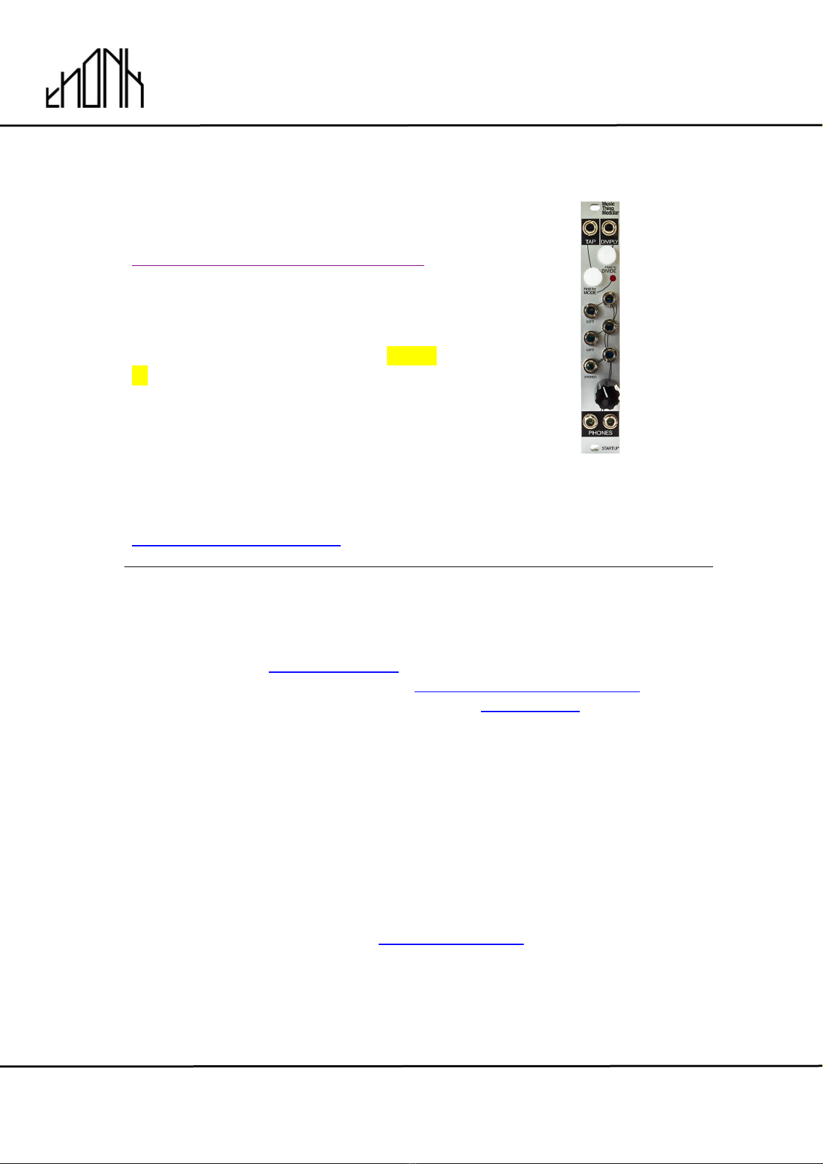
Music Thing Modular
Startup Module
Eurorack DIY Kit
Instructions
Version 1
OVERVIEW
For the most recent version of this
document please visit
https://thonk.co.uk/documents/startup/
This document has hi-res images. ZOOM
IN for a closer look
All Thonk kits are sold under our standard Terms and Conditions -
http://www.thonk.co.uk/faq/
DIY INSTRUCTIONS
This document gives detailed instructions that assume you have purchased a
complete kit from www.thonk.co.uk. It also assumes no previous knowledge
of electronics. To learn to solder try https://youtu.be/IpkkfK937mU and the
Adafruit guide to excellent soldering – http://bit.ly/1l77tF4!
Watch and understand that whole YouTube video! If you’re not achieving the
results shown in the video then you need to buy new tools or seek advice.
You will not end up with a working module otherwise.
TOOLS REQUIRED
Soldering iron, snipe nose pliers, masking tape, small flat head screwdriver
and diagonal cutters AKA snips AKA side-cutters. A Digital Multimeter is
always helpful for checking for bad solder joints and continuity. Thonk sell a
range of inexpensive tools here - http://bit.ly/1jxqF3n
!
!
April 30th 2019 www.thonk.co.uk 2
Music Thing Modular
Startup Module
Eurorack DIY Kit
Instructions
Version 1
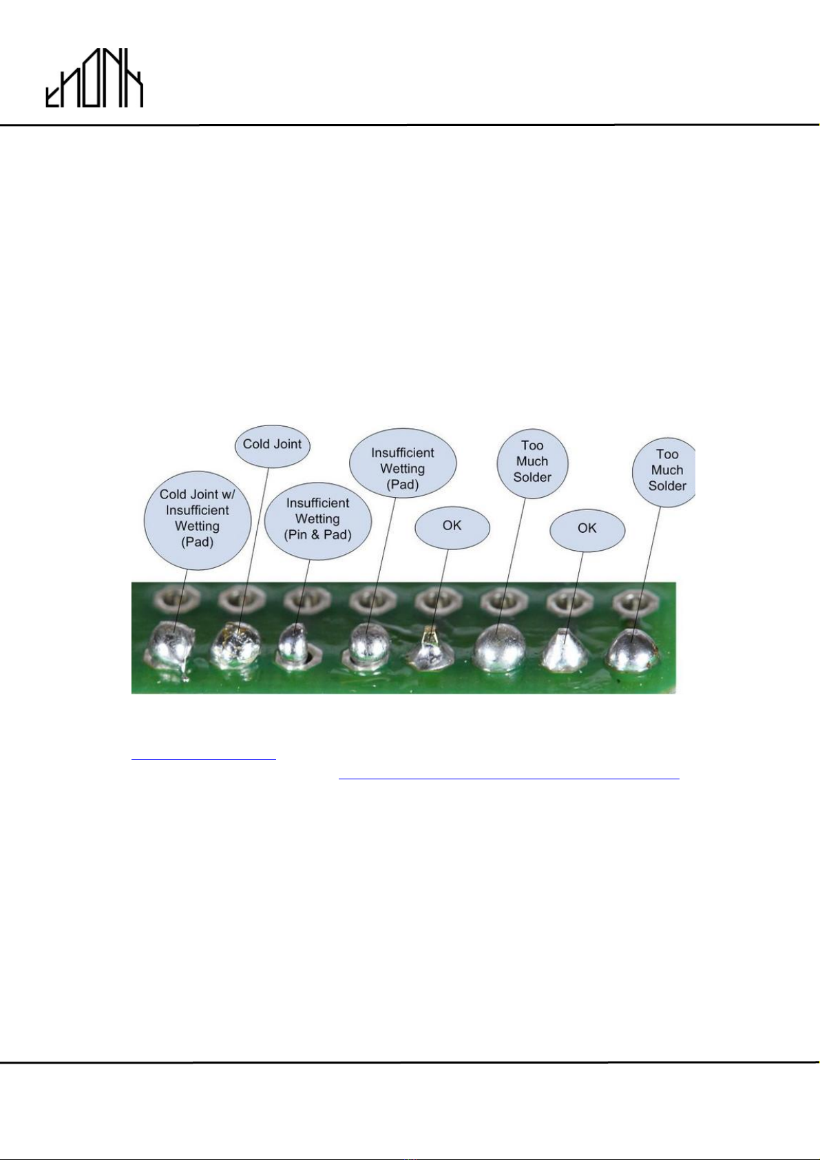
SOLDER JOINTS
Your solder joints should look like those shown as ‘OK’ below, they should
have that neat conical shape on BOTH sides of the PCB. If they don’t look
the same on both sides then stop! Work out why from the soldering guides
linked and don’t continue until you are getting those results.
This isn’t just OCD talking, you are very likely to end up with a destroyed,
damaged or defective unit if you’re not hitting that standard.
This photo is from the Adafruit guide to excellent soldering -
http://bit.ly/1jxqF3n and is reproduced under an Attribution-Sharealike
creative commons license - http://creativecommons.org/licenses/by-sa/3.0/
!
!
April 30th 2019 www.thonk.co.uk 3
Music Thing Modular
Startup Module
Eurorack DIY Kit
Instructions
Version 1
STARTUP BUILD INSTRUCTIONS
1.
Start by emptying the component bag into one bowl or container. This
makes it much easier to pick parts as you need them and you’re less likely
to lose anything.
2.
All of the SMD components on the PCB have been placed and soldered by
robots, so this is a very quick build. However, it does require very careful
and precise soldering.!
Avoid touching the SMD components with your hands and be very careful
not to touch them with your soldering iron.
Take your time, and use an iron with a reasonably small tip!
!
!
!
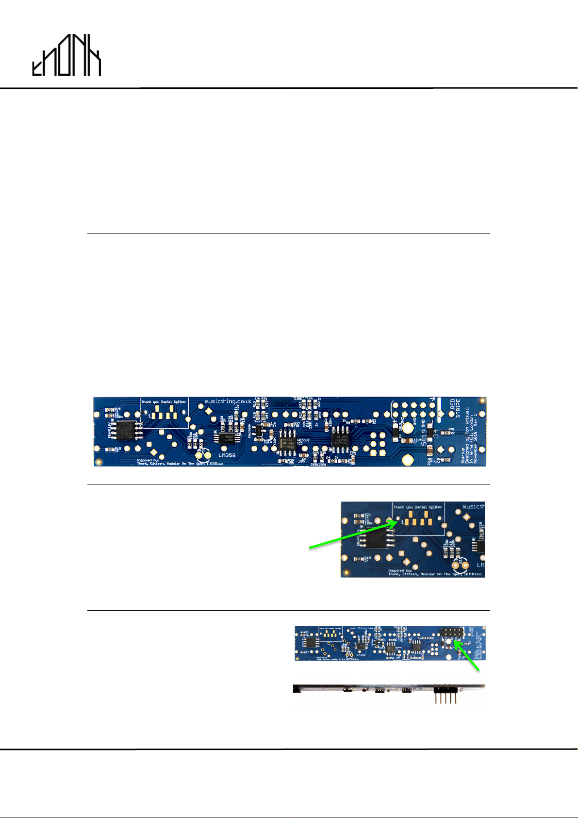
3.
There are 6 pads towards the top of
the board marked 'Thank you,
Daniel Spilliker' - these are
programming pads, and will not be
populated!
4.
Start by soldering the power header.
ENSURE that it is on the correct
side: The long pins should be on the
same side as all the SMD
components. Note: soldering this on
the wrong side will ruin the build!
!
!
April 30th 2019 www.thonk.co.uk 4
Music Thing Modular
Startup Module
Eurorack DIY Kit
Instructions
Version 1
5.
Before soldering the rest of the parts; now is a good time to confirm that
the firmware is correctly programmed on the PCB. We program and test all
boards before sending them out, but this step gives you peace of mind and
shouldn’t be skipped.
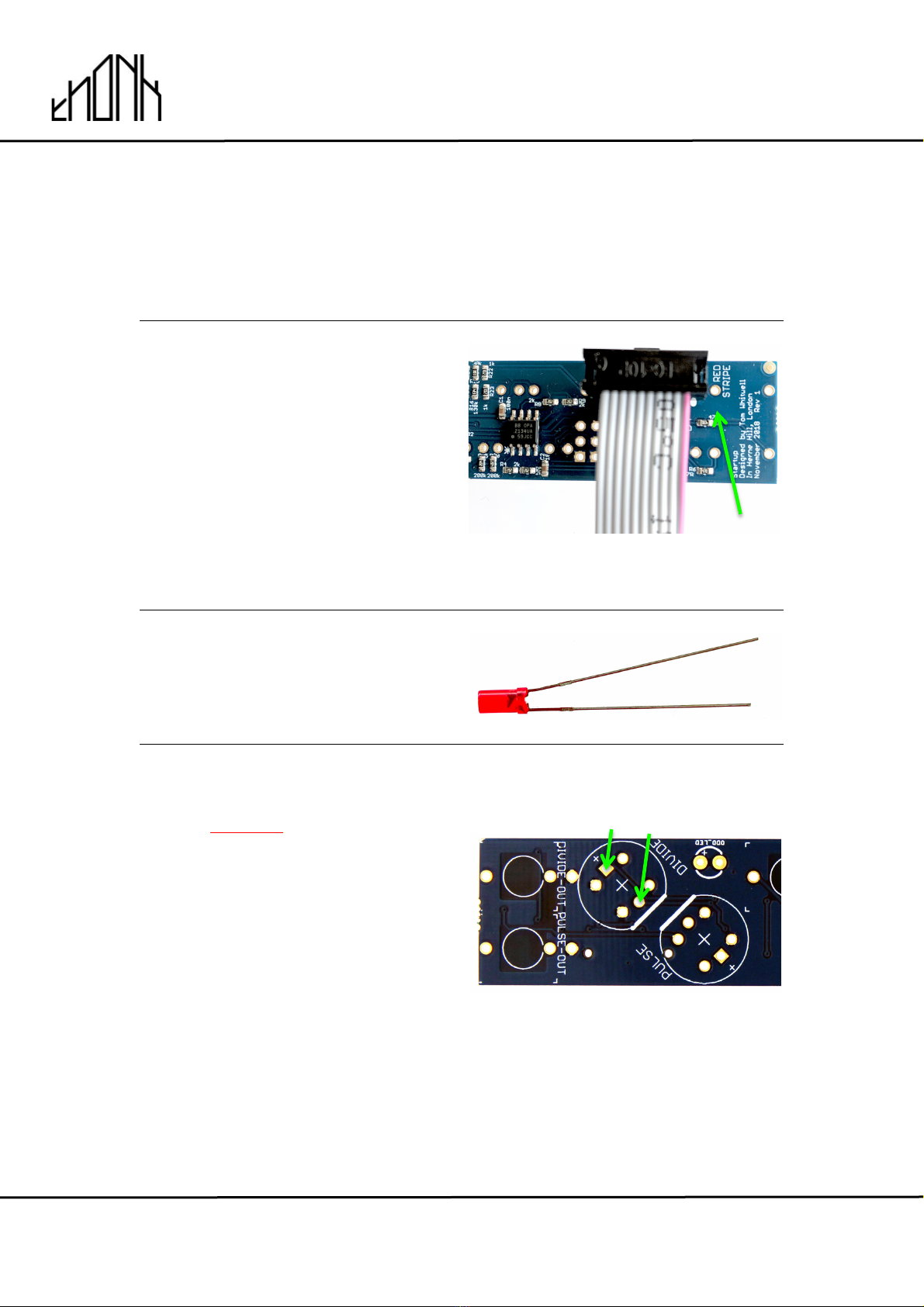
5.1
To do this first take the power cable
and affix it to the power header as
shown - with the red stripe on the
cable facing towards the PCB text:
‘RED STRIPE’.
Then plug the other end of the
power cable into your case power -
but do not switch on the power yet.
5.2
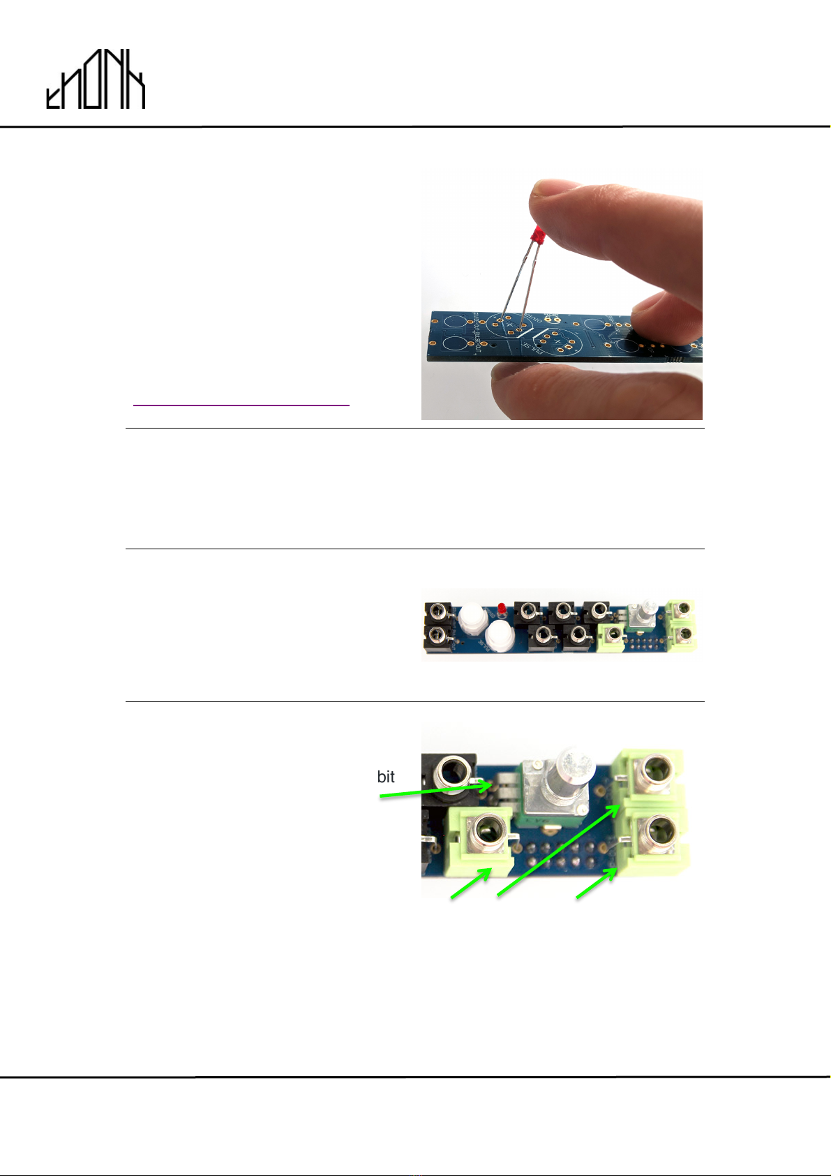
Next locate the red LED and bend
the legs slightly outwards as shown.
5.3
NOTE: DO NOT solder the LED
now – it’s only going to be placed
on the PCB as a test. Do not
solder it!
Now place (do not solder!) the LED
on the PCB with the longer leg
going through the square hole
closest to the edge of the board.
!
!
!
!
Long!Leg!
Short!Leg!
!
!
April 30th 2019 www.thonk.co.uk 5
Music Thing Modular
Startup Module
Eurorack DIY Kit
Instructions
Version 1
5.4
Once in place, switch on your
Eurorack power connecting to the
PCB. Now the LED should start
flashing – this indicates that the
firmware is correctly programmed.
You may need to apply some gentle
sideways pressure to the LED to
ensure that it is contacting the pads.
See this video for a demonstration
of the LED behavior:
https://youtu.be/lavLY58sziA!
6.
Once you have confirmed that the firmware is programmed you can
remove the LED and unplug the power cable.
7.
Next, place all the components onto
the board as shown, but DO NOT
solder anything yet.
8.
Add the potentiometer first, it's a bit
fiddly to get all the legs through.
The stereo sockets are GREEN –
these are marked with crosshatching
on the PCB silkscreen.
The three lowest sockets on the
board are green, all the others are
black mono sockets!
!
!
April 30th 2019 www.thonk.co.uk 6
Music Thing Modular
Startup Module
Eurorack DIY Kit
Instructions
Version 1
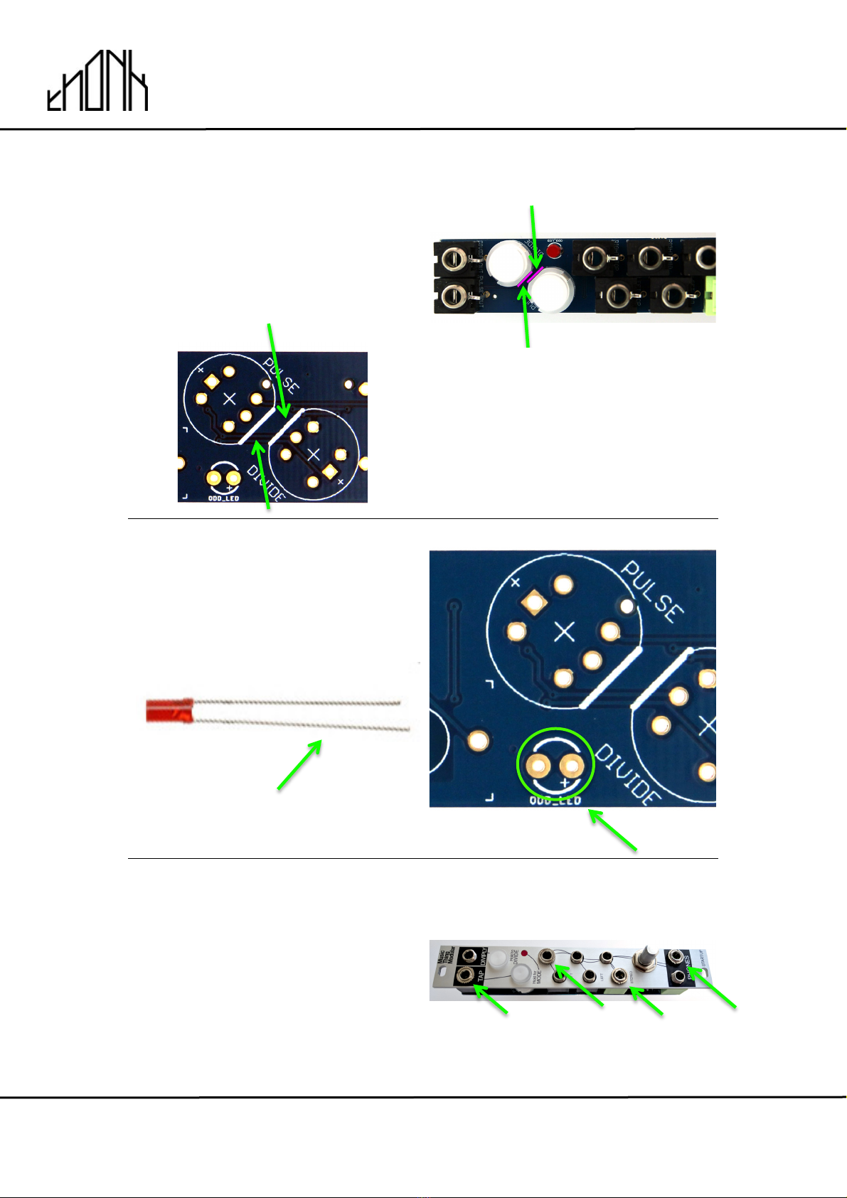
9.
Be careful to align the pushbuttons
correctly: They have one flat side,
which is clearly marked on the PCB
silkscreen. The two flat sides face
towards each other on the middle of
the PCB.!
NOTE: The real PCB has white lines
to show the flat edge - not pink.
10.
Orientation is also vital for the Red
LED. The LONGER leg of the LED
must go into the hole marked on the
PCB with a + sign.!
Longer leg goes to +
11.
Once all the components are in
place, but NOT SOLDERED, put on
the front panel and screw on 3 or 4
nuts at the top, middle, and bottom
of the board on alternating sides.
This will take a little gentle jiggling
about.
Flat edge
Flat edge

!
!
April 30th 2019 www.thonk.co.uk 7
Music Thing Modular
Startup Module
Eurorack DIY Kit
Instructions
Version 1
12.
Solder the topmost (Tap / Diviply) sockets first. Then solder the green
sockets at the bottom, so the whole arrangement holds together.
13.
Now, gently push the first
pushbutton into place. Don't depress
the button, just push it gently so its
pins come up through the holes in
the PCB. Solder ONE corner pin
into place while holding the
button firmly in place.
!
Then do the same with the second
pushbutton.
14.
Now, turn over the module and
check that the pushbuttons can be
clicked - that they move smoothly
without rubbing too much on the
sides. If not, you can adjust by
melting the corner pins that you’ve
soldered. Once you're happy, solder
all 6 pins on each button.

!
!
April 30th 2019 www.thonk.co.uk 8
Music Thing Modular
Startup Module
Eurorack DIY Kit
Instructions
Version 1
15.
Next, push the LED into place,
ensure it's in the hole and - if using a
flat head LED - hold it flush to the
front surface of the panel with a bit
of masking tape or Blu-tac. Solder
the two legs and then snip off the
excess leads.
16.
Finally, solder ALL the other points on the back - all the sockets and the
potentiometer.
!
Be careful down around the 6 pins of the potentiometer - there's a socket
'leg' very nearby, ensure there are no big blobs of solder causing a short
circuit.!
!
There are LOTS of legs, and they're close to lots of tiny components. Go
slowly and make sure you have plenty of light and a clean soldering tip.
Once you've finished, check to make sure you haven’t missed a point
somewhere.
17.
Now you can screw on all the rest of
the nuts and place the knob onto the
pot.

!
!
April 30th 2019 www.thonk.co.uk 9
Music Thing Modular
Startup Module
Eurorack DIY Kit
Instructions
Version 1
18.
The module is now complete. Affix
the power cable as shown with the
red stripe on the cable facing
towards the PCB text: ‘RED STRIPE’
19.
You can find the Quickstart manual for STARTUP here:
!
https://musicthing.co.uk/collateral/Startup_Rev1_Manual.pdf!
Table of contents
Other Thonk Recording Equipment manuals


