PE RF O RMAN CE S PEC I F I CAT IONS
FREQUENCY RESPONSE
. +0, -0.5d8 Írom 2OHz to 20,000H2
TOTAT HARMONIC DISTORTION
O.OO2% maximum Írom 2OHz to 20,000H2
SICNAT TO NOISE RATIO
Phono: S6dB (A Weighted)
High Level: 97dB (Aweighted)
RATED OUTPUT VOTTAGE
Main and Outputs 1 and 2:2.5Vrms
MAXIMUM VOTTAGE OUTPUT
Main and Outputs 1 and 2:1OVrms
OUTPUT IMPEDANCE
240 ohms
INPUT IMPEDANCE
Phono:47k ohms, 65pf
High Level: 22k ohms
SENS¡TIVITY
Phono:4.5mV for rated output
High Level: 450mV for rated output
MAXIMUM INPUT S¡CNAI
Phono:5OmV
High Level:5V
VOTTAGE GAIN
Phono to Tape Out:40d8
High Level to Tape Out:OdB
High Level to Main Out: 15dB
POWER REQUTREMENTS
1 O0Volts, 5O/60H2, 30 Watrs
1 1 OVolts, 5Ol6OHz, 30 Watrs
1 20Volts, 5Ol6OHz, 30 Watts
22oVolts, 5O/6OHz, 30 Watts
230Volts, 5O/6OHz, 30 Watts
240Volts, 5Ol6OHz, 30 Watrs
Note: Refer to the rear panel of the C42 for
the correct voltage
DIMENSIONS
Width: 17-1/2 inches (44.5cm)
Height: 5-3lB inches (13.7cm)
Depth: 1B-1/2 inches (44.5cm) ,including
clearance for connectors
NOTES
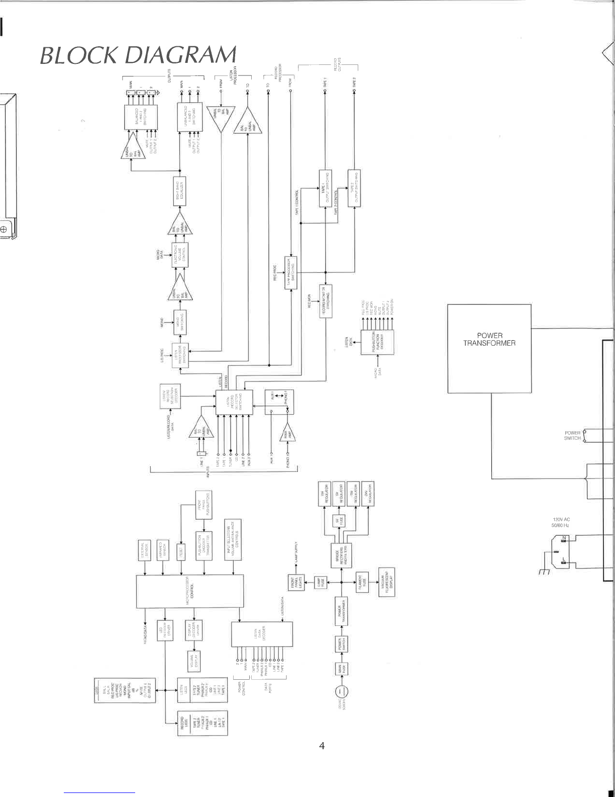
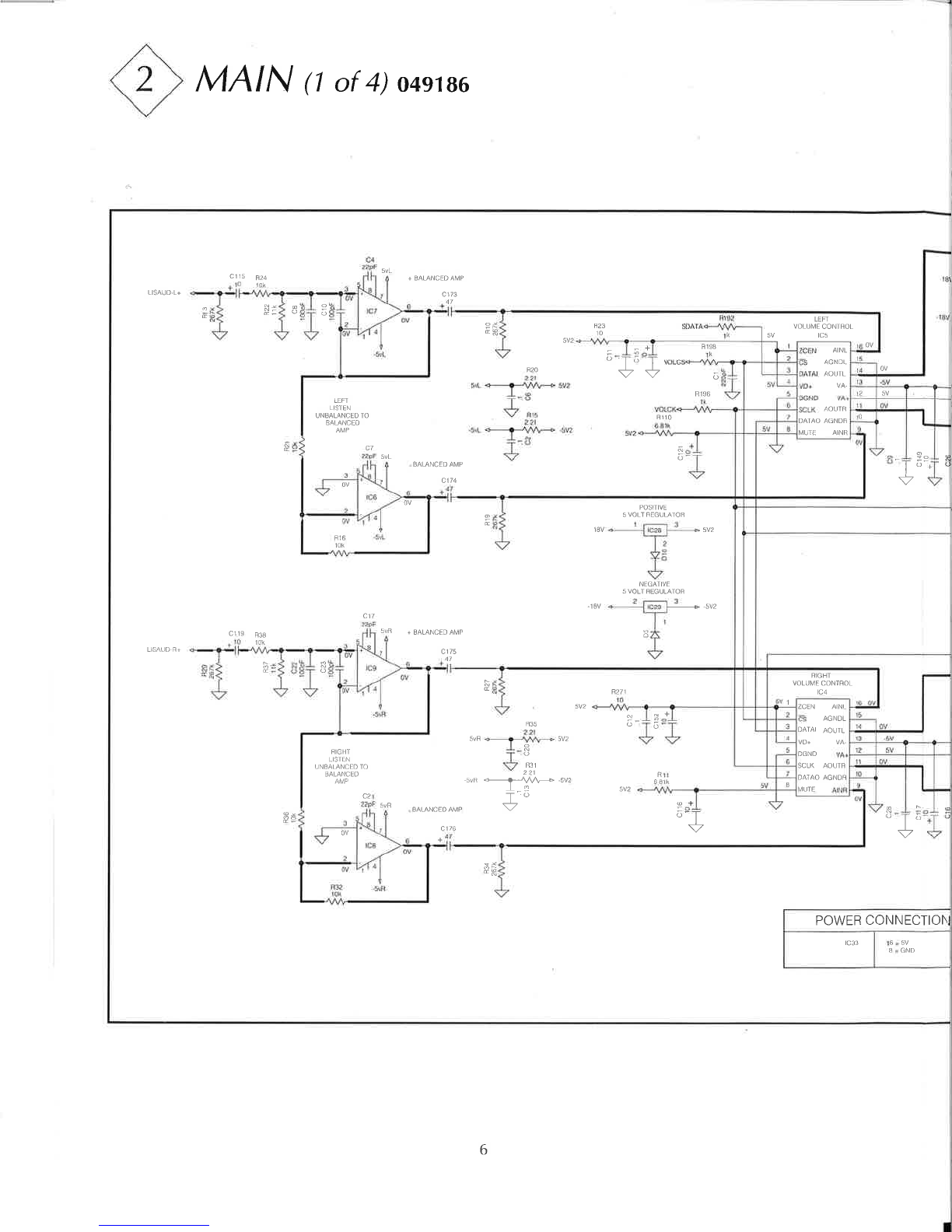
1 . The heavy notes on the schematic denote
the primary signal path.
2. Unless otherwise noted, all voltages
indicated on the schematics are measured
under the following conditions:
a. AC input af "l2O volts, 50/60H2.
b. All voltages are +/-10% with respect to
ground. A high impedance (10 megaohm)
voltmeter must be used.
3. Unless otherwise specified:
a. Resistor values are in ohms.
b. Capacitor values are microfarads (uF).
c. lnductor values are in microhenries (uH)
4. On PC board drawings, Square pad
indicates:
a. Polarized Capacitors - Positive
b. Diodes - Cathode
c. Others - Pin 1
5. WARNINC: ^
Parts marked with the symbol ,/ ! \ have
critical characteristics. Use only replacement
parts recommended by the manufacturer.
2