McLean SPECTRACOOL G57 User manual

© 2012 Pentair Technical Products 89055585
Rev. F P/N 10-1008-243
Protecting Electronics.
Exceeding Expectations.™
Pentair Technical Products
2100 Homan Way
Anoka, MN 55303
+1-763-323-8200
+1-763-576-3200
www.McLeanCoolingTech.com
INSTRUCTION MANUAL
SPECTRACOOL™
Air Conditioner
G57

© 2012 Pentair Technical Products 89055585
- 2 -
TABLE OF CONTENTS
RECEIVING THE AIR CONDITIONER .............................................................................................................................................................. 3
HANDLING AND TESTING THE AIR CONDITIONER ................................................................................................................................. 3
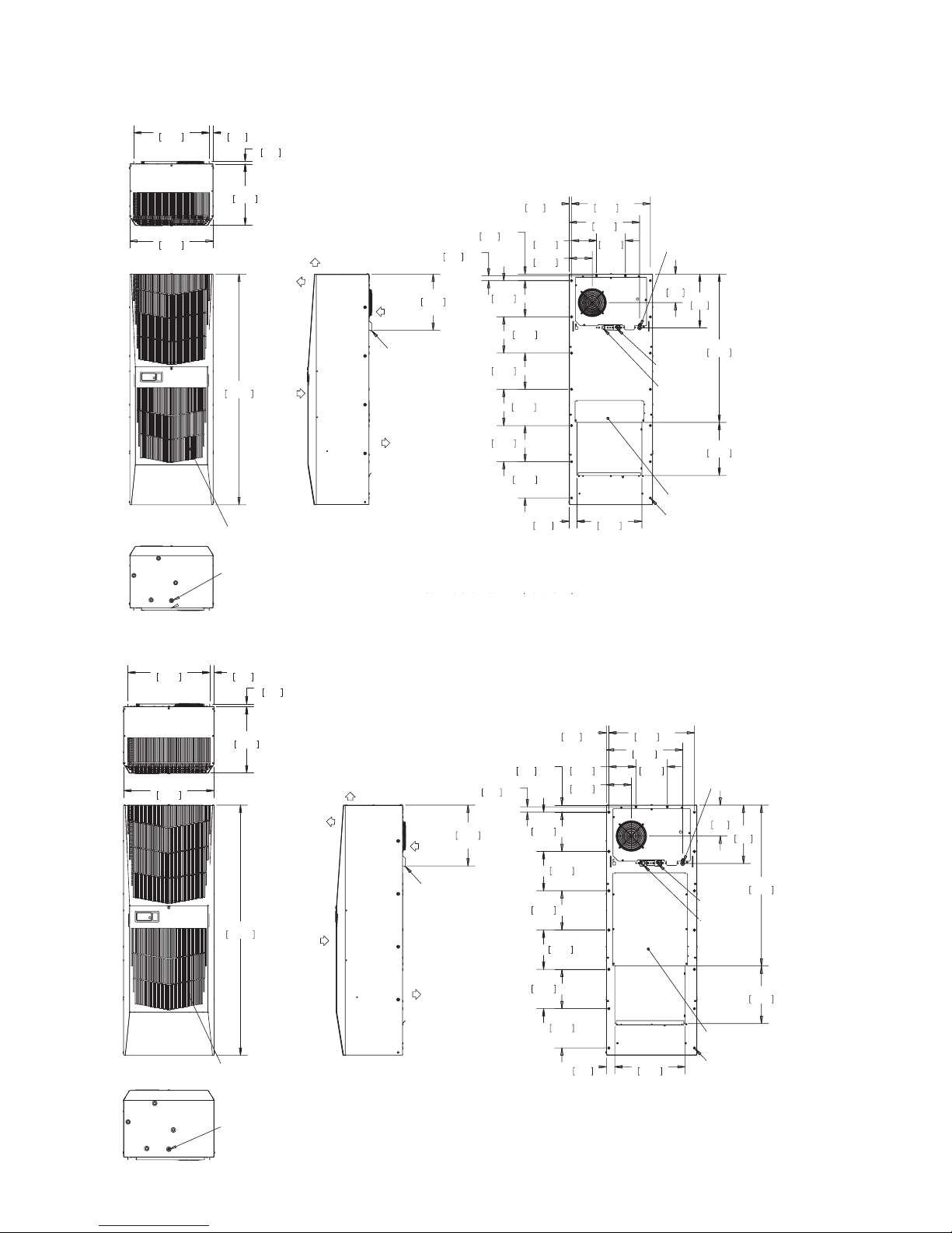
DIMENSIONAL DRAWINGS ............................................................................................................................................................................. 4
20000 BTU/Hr. (G572026GXXX, G572026G2XX) ............................................................................................................................. 4
20000 BTU/Hr. (G572046G15X) ............................................................................................................................................................ 4
HOW TO READ MODEL NUMBERS ............................................................................................................................................................... 5
INSTALLATION INSTRUCTIONS ..................................................................................................................................................................... 5
TECHNICAL INFORMATION ............................................................................................................................................................................ 7
Sequence of Operation ........................................................................................................................................................................... 7
Heating .................................................................................................................................................................................................. 7
Cooling .................................................................................................................................................................................................. 7
Standard and Optional Component Operation ............................................................................................................................. 7
Thermostat ........................................................................................................................................................................................... 7
Head Pressure Control ..................................................................................................................................................................... 7
Contactor .............................................................................................................................................................................................. 8
Freezestat ............................................................................................................................................................................................. 8
Time Delay Relay ................................................................................................................................................................................ 8
200 V to 230 V Transformer (G572026G2XX only) .................................................................................................................. 8
Phase Monitor (G572046GXXX only) .......................................................................................................................................... 8
460 V to 230 V Transformer (G572046GXXX only) .................................................................................................................. 8
230 V to 10 V Transformer (optional) .......................................................................................................................................... 8
230 V to 24 V Transformer and Relay (optional) ...................................................................................................................... 8
Refrigerant Properties Chart (R407c).................................................................................................................................................. 9
Unit Characteristics .................................................................................................................................................................................10
Functional Data ........................................................................................................................................................................................10
Wire Diagrams and Schematics ..........................................................................................................................................................11
G57 208V 1-Phase Generic Wire Diagram (actual unit options may vary) ..................................................................11
G57 208V 1-Phase Generic Schematic (actual unit options may vary) ........................................................................12
G57 230V 1-Phase Generic Wire Diagram (actual unit options may vary) ..................................................................13
G57 230V 1-Phase Generic Schematic (actual unit options may vary) ........................................................................14
G57 400/460V 3-Phase 50/60hz Generic Wire Diagram (actual unit options may vary) ........................................15
G57 400/460V 3-Phase 50/60hz Generic Schematic (actual unit options may vary) ..............................................16
SERVICE DATA ...................................................................................................................................................................................................17
Components List ......................................................................................................................................................................................17
MAINTENANCE .................................................................................................................................................................................................18
Compressor ...............................................................................................................................................................................................18
Inlet Air Filter .............................................................................................................................................................................................18
How To Remove, Clean or Install a New Inlet Air Filter ..............................................................................................................18
Condenser and Evaporator Air Movers ............................................................................................................................................19
Refrigerant Loss........................................................................................................................................................................................19
TROUBLE SHOOTING ......................................................................................................................................................................................20
Basic Air Conditioning Trouble Shooting Check List ..................................................................................................................20
Symptoms and Possible Causes: ........................................................................................................................................................21
WARRANTY ........................................................................................................................................................................................................22
RETURN AND REPAIR POLICY ......................................................................................................................................................................22
LIMITATION OF LIABILITY ..............................................................................................................................................................................23

© 2012 Pentair Technical Products89055585 - 3 -
RECEIVING THE AIR CONDITIONER
Inspect the air conditioner. Check for concealed damage that may have occurred during shipment. Look for dents,
scratches, loose assemblies, evidence of oil, etc. Damage evident upon receipt should be noted on the freight bill.
Damage should be brought to the attention of the delivering carrier -- NOT to McLean Cooling Technology -- within 15
days of delivery. Save the carton and packing material and request an inspection. Then le a claim with the delivering
carrier.
Pentair Technical Products cannot accept responsibility for freight damages; however, we will assist you in any way
possible.
HANDLING AND TESTING THE AIR CONDITIONER
If the air conditioner has been in a horizontal position, be certain it is placed in an upright, vertical or mounting
position for a minimum of ve (5) minutes before operating.
Do not attempt to operate the air conditioner while it is horizontal
or on its side, back or front. The refrigeration compressor is lled
with lubricating oil. This will cause permanent damage to the air
conditioner and also voids the warranty.
CAUTION
TEST FOR FUNCTIONALITY BEFORE MOUNTING THE AIR CONDITIONER TO THE ENCLOSURE.
Refer to the nameplate for proper electrical current requirements, and then connect the power cord to a properly
grounded power supply. Minimum circuit ampacity should be at least 125% of the amperage shown in the design
data section for the appropriate model. No other equipment should be connected to this circuit to prevent
overloading.
Immediately after applying power, the evaporator blower (enclosure air) should start running. Operate the air
conditioner with the compressor running for ve (5) to ten (10) minutes. You will need to set the cooling thermostat
below the ambient temperature to operate the compressor.
Condenser air temperatures should be warmer than normal room temperatures within a few minutes after the
condenser impellers start.
See Sequence of Operation on page 7 for specics on how the unit operates when powered up.

© 2012 Pentair Technical Products 89055585
- 4 -
DIMENSIONAL DRAWINGS
20000 BTU/Hr. (G572026GXXX, G572026G2XX)
$&&(66+2/(72
>@2''5$,1678%
&/($1$%/(5(86$%/(
$/80,180,1/(7),/7(5
%(+,1'5(029$%/(3$1(/
(1&/2685(
$,5,1
$0%,(17
$,5,1
:$50
$,5287
5(029$%/(
+$1*,1*
7$%6
&22/
$,5287
127(
$33529(727<3(5;
02817,1**$6.(76833/,('1276+2:1
$&&(663$1(/)25
237,21$/+($7(5
81&
02817,1*+2/(6
32:(5,1/(7
&22/,1*
7+(50267$7
+($7
7+(50267$7
237,21$/
88040022
20000 BTU/Hr. (G572046G15X)
$&&(663$1(/
)25+($7(5
81&
02817,1*+2/(6
32:(5,1/(7
&22/,1*
7+(50267$7
+($7
7+(50267$7
$&&(66+2/(72
2''5$,1678%
&/($1$%/(5(86$%/(
$/80,180,1/(7),/7(5
%(+,1'5(029$%/(3$1(/
127(
$33529(727<3(5
02817,1**$6.(76833/,('1276+2:1
(1&/2685(
$,5,1
$0%,(17
$,5,1
:$50
$,5287
5(029$%/(
+$1*,1*
7$%6
&22/
$,5287
89059779
WARM
AIR OUT
AMBIENT
AIR IN
ACCESS HOLE TO .375 [9.5]
OUTSIDE DIAMETER DRAIN STUB
NOTE:
1. APPROVE TO TYPE 3R, 4, 4X 12
2. MOUNTING GASKET SUPPLIED (NOT SHOWN)
ACCESS PANEL FOR
OPTIONAL HEATER
1/4 - 20 MOUNTING
HOLES (16)
ENCLOSURE
AIR IN
POWER INLET
COOL
THERMOSTAT
COOL AIR
OUT
REMOVABLE
HANGING TABS
HEAT
THERMOSTAT
(OPTIONAL)
CLEANABLE, REUSABLE,
ALUMINUM INLET FILTER
BEHIND REMOVABLE PANEL
WARM
AIR OUT
AMBIENT
AIR IN
ACCESS HOLE TO .375 [9.5]
OUTSIDE DIAMETER DRAIN STUB
NOTE:
1. APPROVE TO TYPE 3R, 4, 12
2. MOUNTING GASKET SUPPLIED (NOT SHOWN)
ACCESS PANEL FOR
OPTIONAL HEATER
1/4 - 20 MOUNTING
HOLES (16)
ENCLOSURE
AIR IN
POWER INLET
COOL
THERMOSTAT
COOL AIR
OUT
REMOVABLE
HANGING
TABS
HEAT
THERMOSTAT
(OPTIONAL)
CLEANABLE, REUSABLE,
ALUMINUM INLET FILTER
BEHIND REMOVABLE PANEL

© 2012 Pentair Technical Products89055585 - 5 -
HOW TO READ MODEL NUMBERS
G57 20 2 6 G150
12345
1. Identies the type/family of air conditioner and the approximate height (i.e. G57 = Global family about
57 inch high).
2. This is the air conditioner’s listed capacity in BTU/Hr. at rated conditions. (i.e. 20 = 20,000 BTU/Hr. at
131/131 F)
3. 2 = 208 or 230 Volt, 4 = 460 Volt.
4. 6 = 50/60 Hz or 60 Hz only.
5. Unique set of numbers for each air conditioner which identies the accessories on a model. All –G2XX
models are 208 Volt 60 Hz.
INSTALLATION INSTRUCTIONS
1. Inspect the air conditioner and verify correct functionality before mounting the air conditioner. See
HANDLING AND TESTING THE AIR CONDITIONER on page 3.
2. Using the mounting gasket kit provided with the unit, install gaskets to the air conditioner.
3. Mount air conditioner on enclosure taking care not to damage the mounting gasket. The mounting
gasket is the seal between the air conditioner and the enclosure. Avoid dragging the air conditioner
on the enclosure with the mounting gasket attached as this could cause rips or tears in the gasket and
risk losing the water tight seal.
4. Allow unit to remain upright for a minimum of ve (5) minutes before starting. CAUTION! Air
conditioner must be in upright position during operation.
5. Refer to the nameplate for electrical requirements. Wire the unit to a properly grounded power supply.
Electrical circuit should be fused with slow blow or HACR circuit breaker.
6. Some air conditioners require a remote mounted thermostat. Wire the thermostat outputs to the
appropriate terminals on the 24 VAC terminal strip by noting the locations on the correct wiring
diagram.
7. Set thermostat for required cabinet temperature. Refer to Sequence of Operation on page 7 for
thermostat adjustment and operation.

© 2012 Pentair Technical Products 89055585
- 6 -
88028328 89061034
SURFACE MOUNT SURFACE MOUNT (3-PHASE VOLTAGE)
89045267
PARTIAL RECESS MOUNT
Figure 1
Cutout Dimensions

© 2012 Pentair Technical Products89055585 - 7 -
TECHNICAL INFORMATION
Sequence of Operation
The air conditioner comes standard with two internally mounted thermostats. There are two modes of operation;
heating and cooling. During heating and cooling modes, the evaporator fan will be running.
Heating
When the enclosure temperature is below the heating thermostat setpoint, power is applied to the heaters.
When the enclosure temperature is 10 degrees above the setpoint, the heater is powered o.
Cooling
When the enclosure temperature is above the cooling thermostat setpoint, power is applied through the
thermostat. The compressor is then energized either directly or through a contactor if unit requires one. The
condenser impellers will start immediately if the unit is not equipped with an optional head pressure control
switch. If the unit is equipped with an optional head pressure control switch, the condenser impellers will
start once the refrigerant pressure reaches the setting of the switch. Component specic information is listed
below.
Operating the air conditioner below the minimum ambient temperature or above the maximum ambient
temperatures indicated on the nameplate voids all warranties. DO NOT set the enclosure thermostat to a
temperature lower than 70 F. Doing so can increase the likelihood of frost buildup on the evaporator coil.
The moisture that the enclosure air can contain is limited. If moisture ows from the drain tube continuously
this can only mean that ambient air is entering the enclosure. Be aware that frequent opening of the
enclosure’s door admits humid air that the air conditioner must then dehumidify.
Standard and Optional Component Operation
Thermostat
The G57 air conditioner uses our standard 10-1061-16 thermostat. The thermostat setpoint equals the
temperature that the air conditioner turns o. The thermostat has a 10 F dierential from setpoint until it calls
for cooling or heating. An example of operation is shown below.
For cooling (75-100 F range):
• Thermostat setpoint = 80 F
• Cooling turns on at 90 F
• Cooling turns o at 80 F
For heating (55-65 F range):
• Thermostat setpoint = 55 F
• Heating turns on at 55 F
• Heating turns o at 65 F
NOTE: For testing purposes only, the thermostat stop screw may be removed (on units so
equipped) to allow settings below 70 F. After testing, replace the stop screw and verify that the
thermostat can not be set below 70 F. Extended operation below 70 F can cause coil freeze ups
resulting in reduced load and/or unit damage.
Head Pressure Control
Unit is set at the factory, no adjustment necessary.
At a saturated condenser pressure of 170 psig, the condenser fans will power o. At a saturated condenser
pressure of 240psig, the condenser fans will power on.

© 2012 Pentair Technical Products 89055585
- 8 -
Contactor
The contactor on this model uses a 230 V coil.
Freezestat
The freezestat shuts down the compressor during a frozen evaporator coil condition. The freezestat will
automatically reset when the frozen coil has thawed suciently.
Time Delay Relay
The time delay relay keeps the unit from short cycling after the freezestat resets following a frozen evaporator
coil condition.
200 V to 230 V Transformer (G572026G2XX only)
The 230 V from this transformer powers the compressor, fans, contactor and optional transformers.
Phase Monitor (G572046GXXX only)
The phase monitor protects the compressor from reverse operation. When both lights on the monitor are lit
constant, the power to the unit has been wired correctly and the compressor will operate as designed.
If both lights on the monitor are not lit constant, swap the power leads at the terminal block until both lights
are lit constant.
Factory Settings:
Top dial set at 480 V for 60 Hz operation (Reset to 440 V for 50 Hz operation)
Middle dial set at 5 seconds
Bottom dial set at -20%
460 V to 230 V Transformer (G572046GXXX only)
The 230 V from this transformer powers the fans, contactor and optional transformers. 460 V is only used to
run the compressor.
230 V to 10 V Transformer (optional)
This transformer powers the thermal display only.
230 V to 24 V Transformer and Relay (optional)
This transformer and relay are used to start/stop the unit by using a customer supplied, remote mounted door
switch.

© 2012 Pentair Technical Products89055585 - 9 -
Refrigerant Properties Chart (R407c)
°F °C Bubble Pt Dew Point °F °C Bubble Pt Dew Point
-40 -40 2.9 4.5 60 15.6 117.7 96.8
-35 -37.2 5.2 0.7 65 18.3 128.7 106.7
-30 -34.4 7.9 1.7 70 21.1 140.2 117.2
-25 -31.7 10.7 4 75 23.9 152.5 128.4
-20 -28.9 13.9 6.5 80 26.7 165.5 140.4
-15 -26.1 17.3 9.3 85 29.4 179.2 153.1
-10 -23.3 21.1 12.4 90 32.2 193.6 166.5
-5 -20.6 25.2 15.8 95 35 208.8 180.8
0 -17.8 29.6 19.5 100 37.8 224.9 195.8
5 -15 34.4 23.6 105 40.6 241.8 211.8
10 -12.2 39.6 28 110 43.3 259.6 228.7
15 -9.4 45.2 32.7 115 46.1 278.2 246.5
20 -6.7 51.3 37.9 120 48.9 297.8 265.3
25 -3.9 57.8 43.6 125 51.7 318.3 285.2
30 -1.1 64.7 49.6 130 54.4 339.9 306.1
35 1.7 72.2 56.2 135 57.2 362.4 328.2
40 4.4 80.2 63.2 140 60 386 351.4
45 7.2 88.7 70.7 145 62.8 410.7 375.9
50 10 97.8 78.8 150 65.6 436.5 401.7
55 12.8 107.5 87.5

© 2012 Pentair Technical Products 89055585
- 10 -
Unit Characteristics
Model
G57-2026-G2XX G57-2026-G1XX G57-2046-GXXX
Dimensional Data
Height 57.69” / 1465.4 mm
Width 20.78” / 527.8 mm
Depth 15.28” / 388.1 mm
Unit Weight 219 lbs / 99 kg 197 lbs / 89 kg 207 lbs / 94 kg
Unit Protection Rating Type 12/4/4X/3R
Cooling Data
Refrigerant R407c
Refrigerant Charge 50 oz. 48 oz.
Cooling Capacity at 95 F Enclosure 95
F Ambient (BTU/Hr./W) 18000 16500/18000 17000/18800
Cooling Capacity at Max Conditions
(BTU/Hr./W) 20500 19000/20500 18800/20500
Maximum Ambient Temp 131 F / 55 C
Minimum Ambient Temp -40 F / -40 C
Enclosure Airow 513 / 600 CFM
External Airow 940 / 1070 CFM
Condensate Management Hose discharge / Optional powered C/E
Heating Data
Capacity 3000 W N/A
Electrical Data
Rated Voltage (50/60 Hz) 208 V 230 V 400/460 V 3 phase
Rated Frequency 60 Hz 50 / 60 Hz
Voltage Range +/- 10% of rated
Cooling Amps at Max Conditions 23.5 19.0/22.0 6.0/6.8
Heating Amps 15.0 13.5 NA
Compressor RLA / LRA 13.6/63.0 13.6/63.0 4.3/27.0
Evaporator Fan RLA* 0.8/1.1 0.8/1.1 0.8/1.1
Condenser Fan RLA* 0.8/.86 0.8/.86 0.8/.86
*@230 VAC
Functional Data
Unit Evaporator. Air
In(°F) Amps(A) Condenser
Delta(°F)
Evaporator
Delta(°F)
G572026G1XX 65-80 9.1-12.2 19-32 19-34
80-100 11.1-15.2 26-35 20-34
G572026G2XX 65-80 11.2-14.1 20-32 28-34
80-100 13.1-17.5 26-37 27-34
G572046GXXX 65-80 3.0-4.5 21-32 24-35
80-100 3.5-5.5 26-35 18-30

© 2012 Pentair Technical Products89055585 - 11 -
Wire Diagrams and Schematics
G57 208V 1-Phase Generic Wire Diagram (actual unit options may vary)
TO CUSTOMER
SWITCH
POWER
BLOCK
TRANSFORMER
FREEZESTAT
CONTACTOR
DOOR SWITCH (OPTIONAL)
THERMAL DISPLAY (OPTIONAL)
CAPACITOR WIRE
WITH BELL CRIMP
HEATING
THERMOSTAT
COOLING
THERMOSTAT
RELAY
HEATER
CAPACITOR
1
CAPACITOR
2
ENCLOSURE
AMBIENT
AUTO-TRANSFORMER
COMPRESSOR
HEAD PRESSURE
CONTROL (OPTIONAL)
FOR HEAD PRESSURE CONTROL (HPC) OPTION, TAKE BLK20
OUT AND CONNECT HPC LEADS TO WAGO #2 AND #7
RUN
CAPACITOR
START
CAPACITOR
TO THERMAL
DISPLAY
HEAD PRESSURE
CONTROL LEAD
HEAD PRESSURE
CONTROL LEAD
SUPPRESSOR
(OPTIONAL)
MALFUNCTION
SWITCH
(OPTIONAL)
START
RELAY
COMPRESSOR
HEATER OR
CONDENSATE
EVAPORATOR
(OPTIONAL)
CAPACITOR
3
MANUAL
AUTOMATIC
LIMIT
SWITCHES
ENCLOSURE
IMPELLER 1
CONDENSER
IMPELLER 2
CONDENSER
IMPELLER 3

© 2012 Pentair Technical Products 89055585
- 12 -
G57 208V 1-Phase Generic Schematic (actual unit options may vary)
89044386
AUTOMATIC TRANSFORMER
SUPPRESSOR (OPTIONAL)
AMBIENT IMPELLER
FREEZESTAT, TIME DELAY RELAY
COMPRESSOR HEATER (OPTIONAL)
ENCLOSURE IMPELLER
COMPRESSOR AND
OVERLOAD
CUSTOMER
SWITCH
THERMOSTAT COOLING
CONTACTOR
DOOR SWITCH
TRANSFORMER AND RELAY
(OPTIONAL)
TRANSFORMER WITH TEMPERATURE
DISPLAY (OPTIONAL)
THERMOSTAT HEATING, LIMIT
SWITCHES AND HEATER
AMBIENT IMPELLER WITH HEAD
PRESSURE CONTROL (OPTIONAL)
HARD START RELAY RUN
CAPACITOR START CAPACITOR

© 2012 Pentair Technical Products89055585 - 13 -
G57 230V 1-Phase Generic Wire Diagram (actual unit options may vary)
TO CUSTOMER
SWITCH
POWER
BLOCK
TRANSFORMER
FREEZESTAT
TIME DELAY RELAY
CONTACTOR
DOOR SWITCH (OPTIONAL)
THERMAL DISPLAY (OPTIONAL)
HEATING
THERMOSTAT
COOLING
THERMOSTAT
RELAY
HEATER
CAPACITOR 1
CAPACITOR 2
ENCLOSURE
AMBIENT
COMPRESSOR
HEAD PRESSURE
CONTROL (OPTIONAL)
FOR HEAD PRESSURE CONTROL (HPC) OPTION, TAKE BLK20
OUT AND CONNECT HPC LEADS TO WAGO #2 AND #7
RUN
CAPACITOR
START
CAPACITOR
TO THERMAL
DISPLAY
HEAD PRESSURE
CONTROL LEAD
HEAD PRESSURE
CONTROL LEAD
SUPPRESSOR
(OPTIONAL)
MALFUNCTION
SWITCH
(OPTIONAL)
START
RELAY
COMPRESSOR
HEATER OR
CONDENSATE
EVAPORATOR
(OPTIONAL)
CAPACITOR 3
MANUAL
AUTOMATIC
LIMIT
SWITCHES
ENCLOSURE
IMPELLER 1
CONDENSER
IMPELLER 2
CONDENSER
IMPELLER 3

© 2012 Pentair Technical Products 89055585
- 14 -
G57 230V 1-Phase Generic Schematic (actual unit options may vary)
89047070
SUPPRESSOR (OPTIONAL)
AMBIENT IMPELLER
FREEZESTAT, TIME DELAY RELAY
COMPRESSOR HEATER (OPTIONAL)
ENCLOSURE IMPELLER
COMPRESSOR AND
OVERLOAD
CUSTOMER
SWITCH
THERMOSTAT COOLING
CONTACTOR
DOOR SWITCH TRANSFORMER
AND RELAY (OPTIONAL)
TRANSFORMER WITH
TEMPERATURE DISPLAY
(OPTIONAL)
THERMOSTAT HEATING, LIMIT
SWITCHES AND HEATER
AMBIENT IMPELLER WITH HEAD
PRESSURE CONTROL (OPTIONAL)
HARD START RELAY RUN
CAPACITOR START CAPACITOR

© 2012 Pentair Technical Products89055585 - 15 -
G57 400/460V 3-Phase 50/60hz Generic Wire Diagram (actual unit options may vary)
TO CUSTOMER
SWITCH
TRANSFORMER
FREEZESTAT
COIL COIL
DOOR SWITCH (OPTIONAL)
THERMAL DISPLAY (OPTIONAL)
RELAY
CONDENSER
IMPELLER 2
BLK25 OR HEAD PRESSURE
CONTROL LEAD
BLK25 OR HEAD
PRESSURE
CONTROL LEAD
CONDENSER
IMPELLER 3
COMPRESSOR
VARISTORS
TRANSFORMER
FOR HEAD PRESSURE CONTROL
(HPC) OPTION, TAKE BLK20 OUT AND
CONNECT HPC LEADS TO WAGO #2 AND
COOLING CONTACTOR TERMINAL T1
POWER BLOCK
TO THERMAL
DISPLAY
MALFUNCTION
SWITCH
(OPTIONAL)
TIME DELAY RELAY
TIME DELAY /
PHASE MONITOR
COMPRESSOR
HEATER OR
CONDENSATE
EVAPORATOR
(OPTIONAL)
HEAD PRESSURE
CONTROL (OPTIONAL)
CAPACITOR 3
CAPACITOR 1
HEATER 1
MANUAL
MANUAL
MANUAL
AUTOMATIC
AUTOMATIC
AUTOMATIC
LIMIT SWITCHES
HEATING
THERMOSTAT
HEATING
CONTACTOR
COOLING
CONTACTOR
COOLING
THERMOSTAT
HEATER 2
HEATER 3
CAPACITOR 2
EVAPORATOR
IMPELLER #1
CIRCUIT
BREAKER

© 2012 Pentair Technical Products 89055585
- 16 -
G57 400/460V 3-Phase 50/60hz Generic Schematic (actual unit options may vary)
MTR
MTR
MTR
MTR
CIRCUIT
BREAKER
CONTACTOR
MONITOR
PHASE
R
L1 L2
S
L3
T
AUTO-TRANSFORMER
COMPRESSOR
CLG CONTACTOR
CLG TSTAT
PHASE MONITOR
EVAPORATOR
CONDENSER
CONDENSER
IMPELLER 2
IMPELLER 1
IMPELLER
CAP
CAP
CAP
GRND
RELAY
HPC
COOLING CONTACTOR
HEATING
LIMIT SWT'S
AUTO & MAN
HEATERS
HTG TSTAT
HTG CONTACTOR
FREEZE STAT
VARISTOR
TRANSFORMER W/
TEMP. DISPLAY
(OPTIONAL)
DOOR SWITCH
TRANSFORMER
RELAY (OPTION)
TDR
24V
RSWT.
CUST.
R
89060233
GROUND
MOTOR MOTOR
MOTOR
MOTOR
VARISTOR
COOLING
CONTACTOR
CAPACITOR
CUSTOMER
SWITCH
TIME DELAY RELAY
HEAD
PRESSURE
CONTROL
CAPACITOR
CAPACITOR
COMPRESSOR
PHASE
MONITOR
COOLING CONTACTOR
COOLING THERMOSTAT
TRANSFORMER WITH
TEMPERATURE DISPLAY
(OPTIONAL)
HEATING THERMOSTAT
HEATING CONTACTOR
DOOR SWITCH
TRANSFORMER
RELAY (OPTION)
PHASE MONITOR
RELAY
EVAPORATOR
IMPELLER
CONDENSER
IMPELLER 1
CONDENSER
IMPELLER 2
FREEZESTAT
AUTOMATIC TRANSFORMER
CIRCUIT
BREAKER

© 2012 Pentair Technical Products89055585 - 17 -
SERVICE DATA
Components List
Part Description Part Number
208 V 1 Phase 230 V 1 Phase 460 V 3 Phase
Capacitor, Compressor, Start 10-1032-08 10-1032-08 NA
Capacitor, Compressor, Run 52-6084-09 52-6084-09 NA
Capacitor, Impellers (3) 52-6032-20 52-6032-20 52-6032-20
Circuit Breaker, Compressor NA NA 10-1060-72
Coil, Condenser 89057368 89057368 89057368
Coil, Evaporator 52-6010-25 52-6010-25 52-6010-25
Compressor 89070571 89070571 89073980
Contactor, Compressor 10-1005-42 10-1005-42 10-1005-77
Filter, Air, Reusable 10-1000-108 10-1000-108 10-1000-108
Filter/Dryer 52-6028-06 52-6028-06 52-6028-06
Freezestat 10-1061-05 10-1061-05 10-1061-05
Impeller, Condenser (2) 10-1091-139 10-1091-139 10-1091-139
Impeller, Evaporator 10-1091-167 10-1091-167 10-1091-167
Relay, Compressor Start 10-1042-06 10-1042-06 NA
Relay, Phase Monitor NA NA 10-1005-95
Thermal Expansion Valve 10-1040-46 10-1040-46 10-1040-46
Thermostat, SPDT, 55-100F 10-1061-16 10-1061-16 10-1061-16
Time Delay Relay 10-1005-71 10-1005-71 10-1005-71
Transformer, Input Power 89042952 N/A 10-1006-149
Contactor, Heater N/A N/A 10-1005-42
Heater, 3000 Watt 10-1038-64 10-1038-64 N/A
Heater, 1000 Watt N/A N/A 89059149
Limit Switch (automatic) 10-1033-01 10-1033-01 10-1033-01
Limit Switch (manual) 10-1033-07 10-1033-07 10-1033-07
Malfunction Switch 89082840 89082840 89082840
Head Pressure Control Switch (option) 89083015 89083015 89083015

© 2012 Pentair Technical Products 89055585
- 18 -
MAINTENANCE
Compressor
The compressor requires no maintenance. It is hermetically sealed, properly lubricated at the factory and should
provide years of satisfactory operating service.
Under no circumstances should the access tting covers be loosened, removed or tampered with.
Breaking of seals on compressor access ttings during warranty period will void warranty on hermetic system.
Recharging ports are provided for the ease and convenience of reputable refrigeration repair service personnel for
recharging the air conditioner.
Inlet Air Filter
This air conditioner was designed with a dust resistant condenser coil. This allows it to be run lterless in most
applications. The air conditioner is shipped with a lter in place for your convenience. For lterless operation, simply
remove the lter. Should you decide the lter is necessary in your application, regular maintenance to clean this lter
will assure normal operation of the air conditioner. The easily removable inlet air lter is located behind the front
cover. If necessary lter maintenance is delayed or ignored, the maximum ambient temperatures under which the unit
is designed to operate will be decreased.
If the compressor’s operating temperature increases above designed conditions due to a dirty or clogged lter (or
plugged condenser coil), the air conditioner’s compressor will stop operating due to actuation of the thermal overload
cut-out switch located on the compressor housing. As soon as the compressor temperature has dropped to within
the switch’s cut-in setting, the compressor will restart automatically. However the above condition will continue to
take place until the lter or coil has been cleaned. It is recommended that power to the air conditioner be interrupted
intentionally when abnormally high compressor operating temperature causes automatic shut-down of the unit. The
above described shut-down is symptomatic of a clogged or dirty lter, thus causing a reduction in cooling air ow
across the surface of the compressor and condenser coil.
How To Remove, Clean or Install a New Inlet Air Filter
RP aluminum washable air lters are designed to provide excellent ltering eciency with a high dust holding
capacity and a minimum amount of resistance to air ow. Because they are constructed entirely of aluminum they are
lightweight and easy to service. To achieve maximum performance from your air handling equipment, air lters should
be cleaned on a regular basis.
The inlet air lter is located behind the front access cover. To access the lter, loosen the access-cover screw. Swing top
edge of access cover forward. Slide air lter up and out of retaining tabs. The lter may now be cleaned or new lter
installed.
Cleaning Instructions:
1. Flush the lter with warm water from the exhaust side to the intake side. DO NOT USE CAUSTICS.
2. After ushing, allow lter to drain. Placing it with a corner down will assure complete drainage.

© 2012 Pentair Technical Products89055585 - 19 -
Condenser and Evaporator Air Movers
Impeller motors require no maintenance. All bearings, shafts, etc. are lubricated during manufacturing for the life of
the motor.
If one of the condenser impeller motors (ambient impellers) should fail, it is not necessary to remove the air
conditioner from the cabinet or enclosure to replace the blower. The condenser blower is mounted on its own
bulkhead and is easily accessible by removing the front cover.
Operation of the air conditioner in areas containing airborne
caustics or chemicals can rapidly deteriorate lters, condenser
coils, blowers and motors, etc. Contact Pentair Technical Products
for special recommendations.
CAUTION
Refrigerant Loss
Each air conditioner is thoroughly tested prior to leaving the factory to insure against refrigeration leaks. Shipping
damage or microscopic leaks not found with sensitive electronic refrigerant leak detection equipment during
manufacture may require repair or recharging of the system. This work should only be performed by qualied
professionals, generally available through a local, reputable air conditioning repair or service company.
Should the refrigerant charge be lost, access ports on the suction and discharge sides of the compressor are provided
for recharging and/or checking suction and discharge pressures.
Refer to the data on the nameplate which species the type of refrigerant and the charge size in ounces.
Before recharging, make sure there are no leaks and that the system has been properly evacuated into a deep vacuum.

© 2012 Pentair Technical Products 89055585
- 20 -
TROUBLE SHOOTING
Basic Air Conditioning Trouble Shooting Check List
1. Check manufacturer’s nameplate located on the unit for correct power supply.
2. Turn on power to the unit. The evaporator (Enclosure or “COLD” air) impeller should come on. Is there
airow?
YES, proceed to step 3.
NO, possible problem:
• Open motor winding
• Stuck impeller motor
• Obstructed wheel
Repair or Replace
defective part
3. Check thermostat setting and adjust thermostat to the lowest setting. This should turn the condenser
impellers and the compressor on. Did condenser impellers and compressor come on when the
thermostat was turned on?
YES, proceed to step 4.
NO, possible problem:
• Tripped customer door switch
• Defective thermostat Replace part
4. Are all impellers and the compressor running? If not the unit will not cool properly.
5. Check condenser (Ambient or “HOT” air) impellers for airow. Is there airow?
YES, proceed to step 6.
NO, possible problem:
• Defective thermostat
• Open motor winding
• Stuck impeller motor
• Obstructed wheel
Repair or Replace
defective part
6. Carefully check the compressor for operation - motor should cause slight vibration, and the outer case
of the compressor should be warm. Is the compressor showing signs of this?
YES, wait 5 minutes, then proceed to step 7.
NO, possible problem:
• Defective thermostat
• Defective capacitor
• Defective overload
• Defective relay
Repair or Replace
defective part
7. Make sure the coils are clean. Then check evaporator “air in” and “air out” temperatures. If the
temperatures are the same:
• Possible loss of refrigerant
• Possible bad valves in the compressor
Repair or Replace
defective part
8. To check for a bad thermostat, turn power to the unit o. Remove the upper access panel and place
both thermostat wires onto one terminal (replace upper access panel for safety). This will activate
the switch in the thermostat. Turn the power on and if all impellers and the compressor come on, the
thermostat needs to be replaced.
Other manuals for SPECTRACOOL G57
1
Table of contents
Other McLean Air Conditioner manuals

McLean
McLean T20 User manual

McLean
McLean T15 User manual

McLean
McLean TX23-1424 SERIES User manual

McLean
McLean T62 User manual

McLean
McLean T50 User manual

McLean
McLean T43 User manual

McLean
McLean T53 User manual

McLean
McLean ProAir CR43 User manual

McLean
McLean HB16 Series User manual

McLean
McLean T15-0116-GXXX Series User manual
Popular Air Conditioner manuals by other brands

Mitsubishi Heavy Industries
Mitsubishi Heavy Industries SCM71ZM-S1 Technical manual

CoolAutomation
CoolAutomation CoolMaster 1000D user manual

mundoclima
mundoclima CL23390 Installaton manual

Frigidaire
Frigidaire FRS09PYW1 installation guide

Rotenso
Rotenso MIRAI W user manual

McQuay
McQuay MCK020A Technical manual