- 5 - 10-1008-130 rev.13
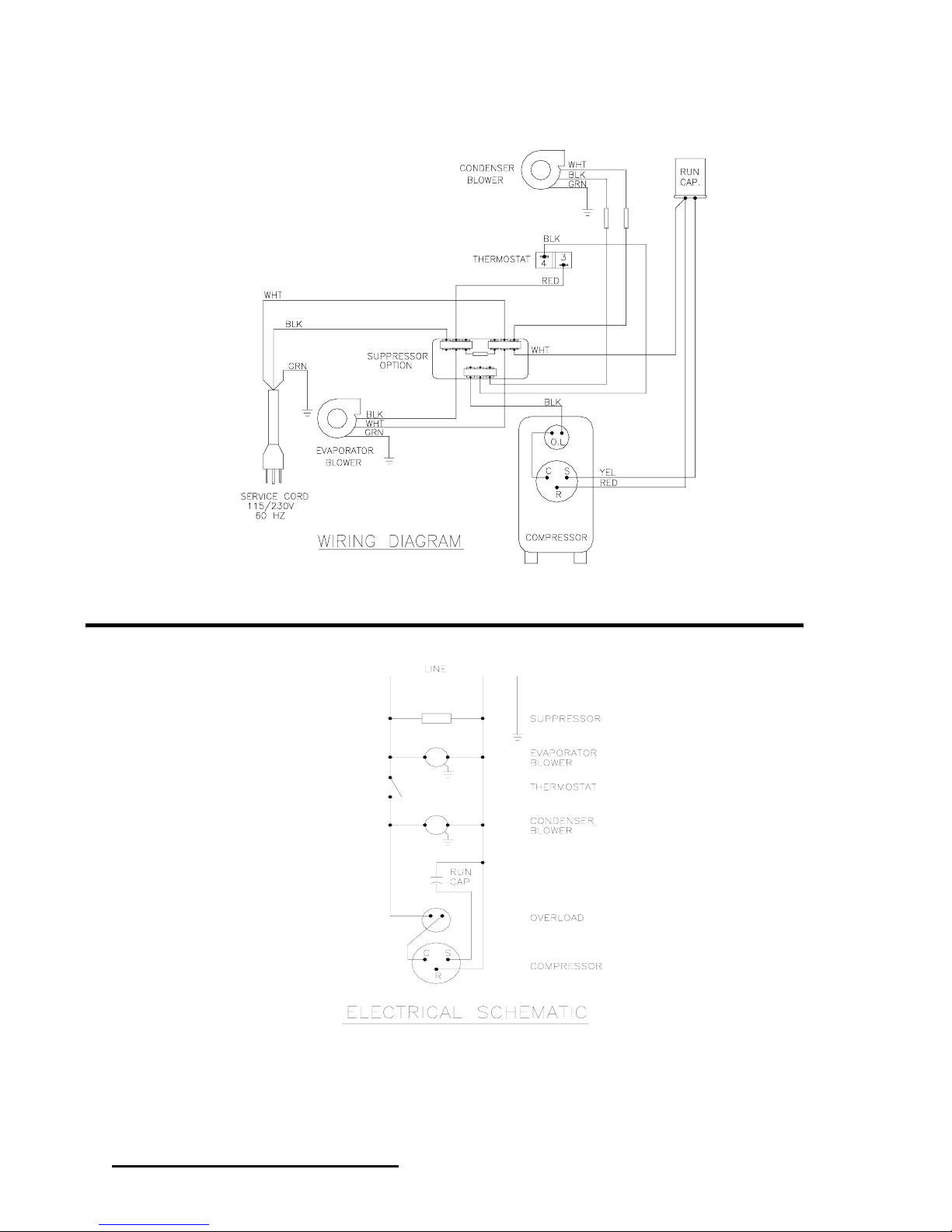
CR43 Wire Diagram, Level I
CR43-0615-XXX CR43-0616-XXX CR43-0625-XXX CR43-0626-XXX
115 Volt 115 Volt 230 Volt 230 Volt
Part Description 50/60 HZ 6000 BTU 60 HZ 6000 BTU 50 HZ 6000 BTU 60 HZ 6000 BTU
Blower, Condenser 38-2019-04 38-2019-04 38-2020-04 38-2020-04
Blower, Evaporator 43-2013-01 43-2013-01 43-2013-02 43-2013-02
Capacitor, Compressor 52-6032-01 52-6032-01 52-6031-01 52-6031-01
Compressor 10-1016-10 10-1016-10 10-1025-08 10-1026-08
Thermal Overload,
Compressor 10-1007-04 10-1007-04 10-1007-08 10-1007-11
Filter, Air, Reusable 10-1000-44 10-1000-44 10-1000-44 10-1000-44
Thermostat, SPST, 55-100F 52-6155-00 52-6155-00 52-6155-00 52-6155-00
Mounting Gasket Kit 43-2000-09 43-2000-09 43-2000-09 43-2000-09
Relay, Compressor N/A N/A N/A N/A
Power Cord 52-6035-01 52-6035-01 52-6035-13 52-6035-13
Evaporator Coil 43-2002-00 43-2002-00 43-2002-00 43-2002-00
CR43-0815-XXX CR43-0816-XXX CR43-0825-XXX CR43-0826-XXX
115 Volt 115 Volt 230 Volt 230 Volt
Part Description 50/60 HZ 8500 BTU 60 HZ 8500 BTU 50 HZ 7500 BTU 60 HZ 8500 BTU
Blower, Condenser 52-6034-10 52-6034-10 52-6025-10 52-6025-10
Blower, Evaporator 38-2019-04 38-2019-04 38-2020-04 38-2020-04
Capacitor, Compressor 52-6032-01 52-6032-01 52-6031-01 52-6031-01
Compressor 10-1016-10 10-1016-10 10-1025-10 10-1026-10
Thermal Overload,
Compressor 10-1007-04 10-1007-04 10-1007-09 10-1007-12
Filter, Air, Reusable 10-1000-44 10-1000-44 10-1000-44 10-1000-44
Thermostat, SPST, 55-100F 52-6155-00 52-6155-00 52-6155-00 52-6155-00
Mounting Gasket Kit 43-2000-09 43-2000-09 43-2000-09 43-2000-09
Relay, Compressor N/A N/A N/A N/A
Power Cord 52-6035-33 52-6035-33 52-6035-13 52-6035-32
Evaporator Coil 43-2002-01 43-2002-01 43-2002-01 43-2002-01
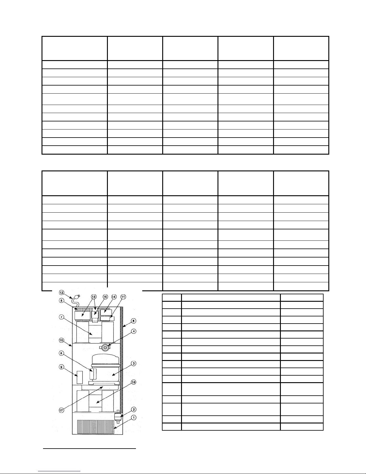
Figure 2
Part Description Part No.
1 Condenser Coil 43-2001-00
2 Filter, drier. Refrigerant 52-6028-00
3 Compressor See Table A
4 Hot gas bypass valve 52-6027-00
5 Evaporator Coil See Table A
6 Inlet air filter, reusable aluminum 10-1000-44
7 Evaporator blower See Table A
8 Compressor thermal overload switch See Table A
9 Capacitor, compressor See Table A
10 Mounting gasket kit 43-2000-09
11 Terminal block 86912
12 Power cord See Table A
13 Temperature controller Level I Level
II (digital) 52-6155-00
10-1106-14
14 Relay (Level II only) 10-1005-21
15 Transformer (Level II only) 115v / 230v 10-1006-94 10-
1006-93
16 Condenser Blower See Table A
17 Condensate Pan 43-2017-00