McLean TX23-1424 SERIES User manual

10-10088-22221-1-ReRev. 3
INSTRUCTION MANUAL
McLean Cooling Technology
11611 Business Park Blvd N
Champlin, MN 55316 USA
Tel 763-323-8200
Fax 763-576-3200
www.McLeanParts.net
ClimaGuard ™
Outdoor
Heat Exchanger
All Models
Exceeding Expectations.
™

10-1008-221 Rev 3 Page 1
INSTRUCTION MANUAL
TABLE OF CONTENTS
Receiving the Heat Exchanger .................................................................................... 1
Testing the Heat Exchanger ........................................................................................ 1
Installation...................................................................................................................2
Principles of Operation................................................................................................ 2
Maintenance ................................................................................................................ 2
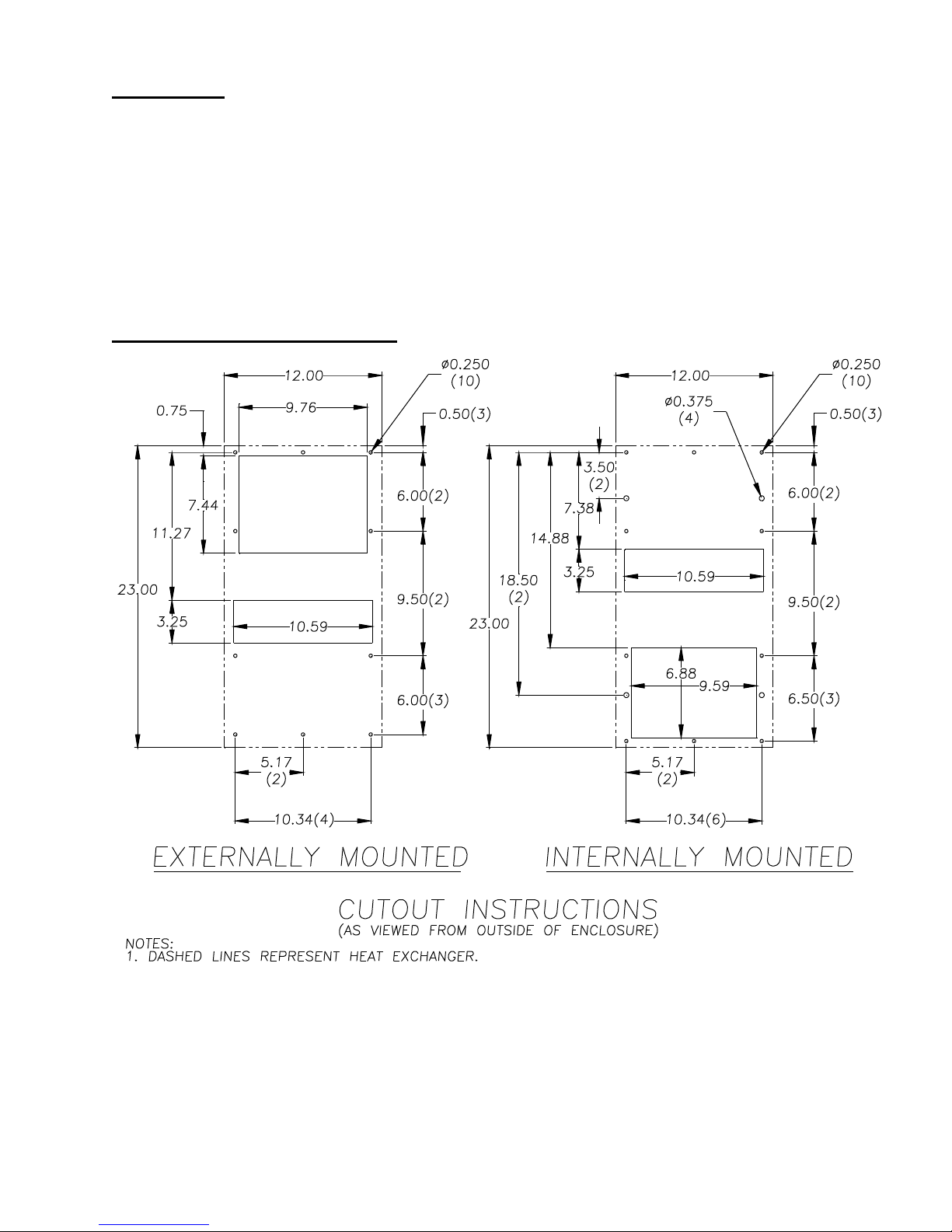
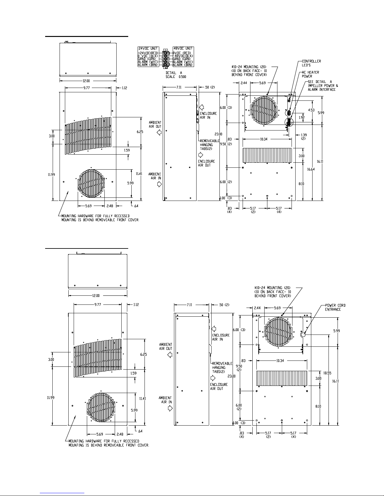
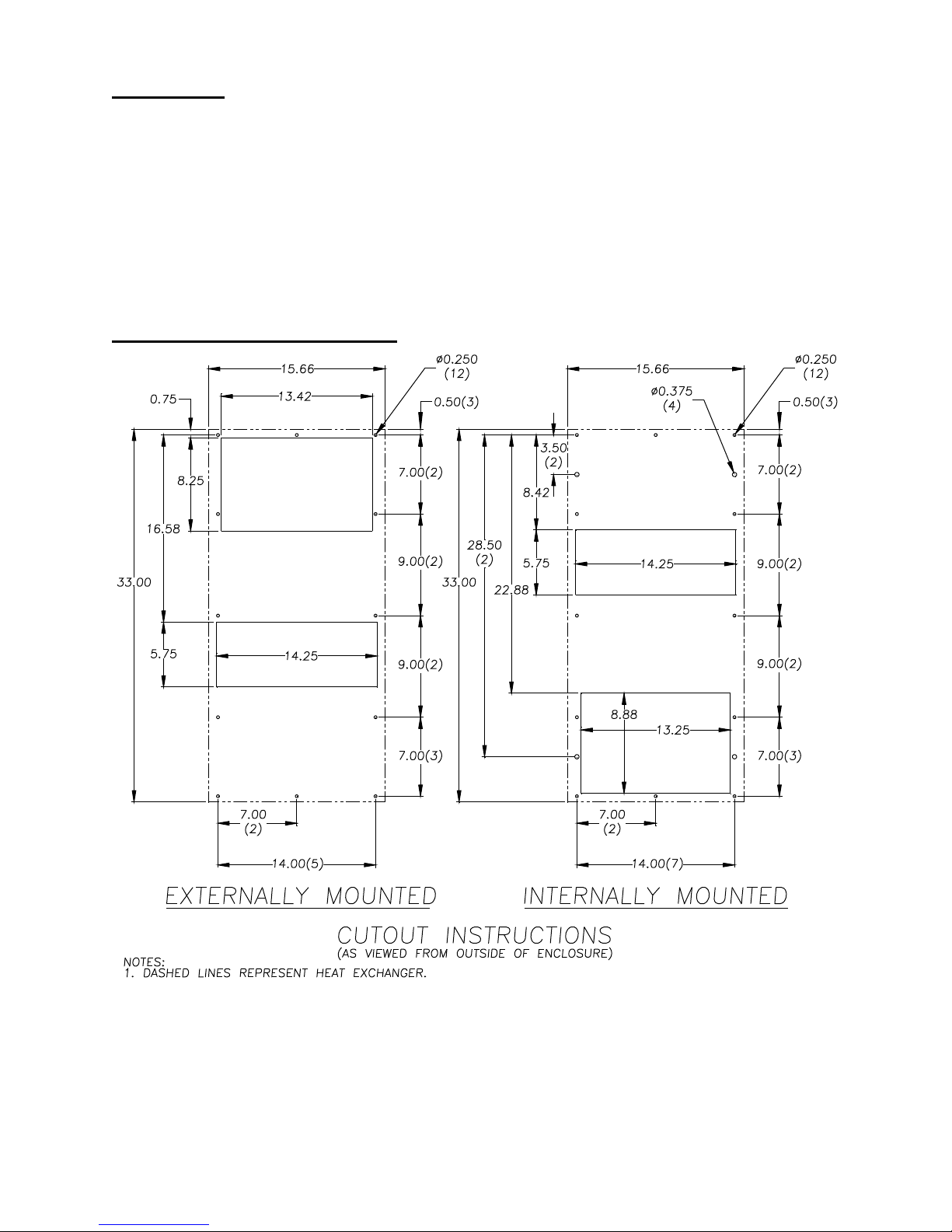
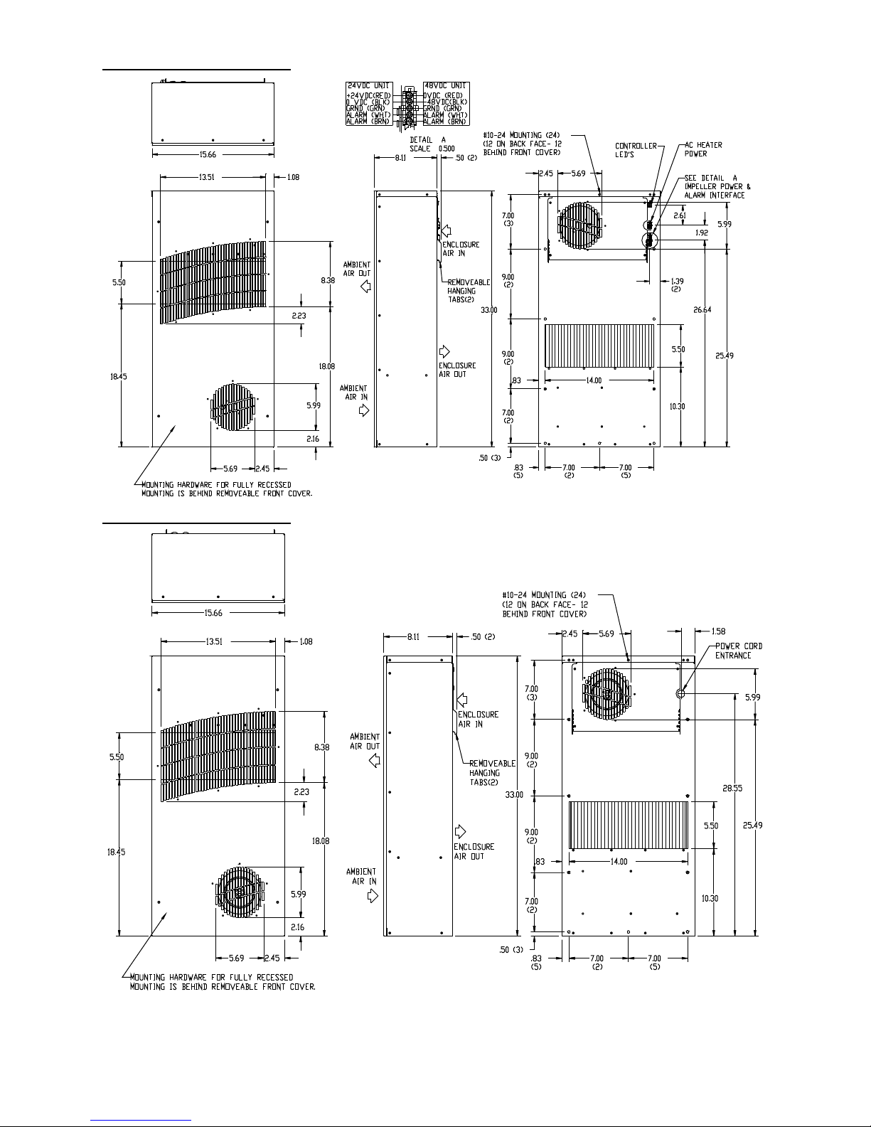
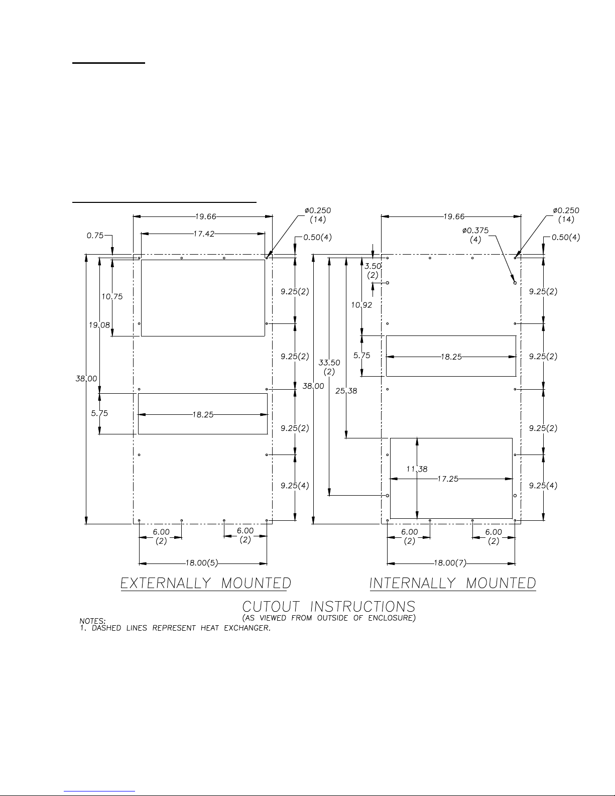
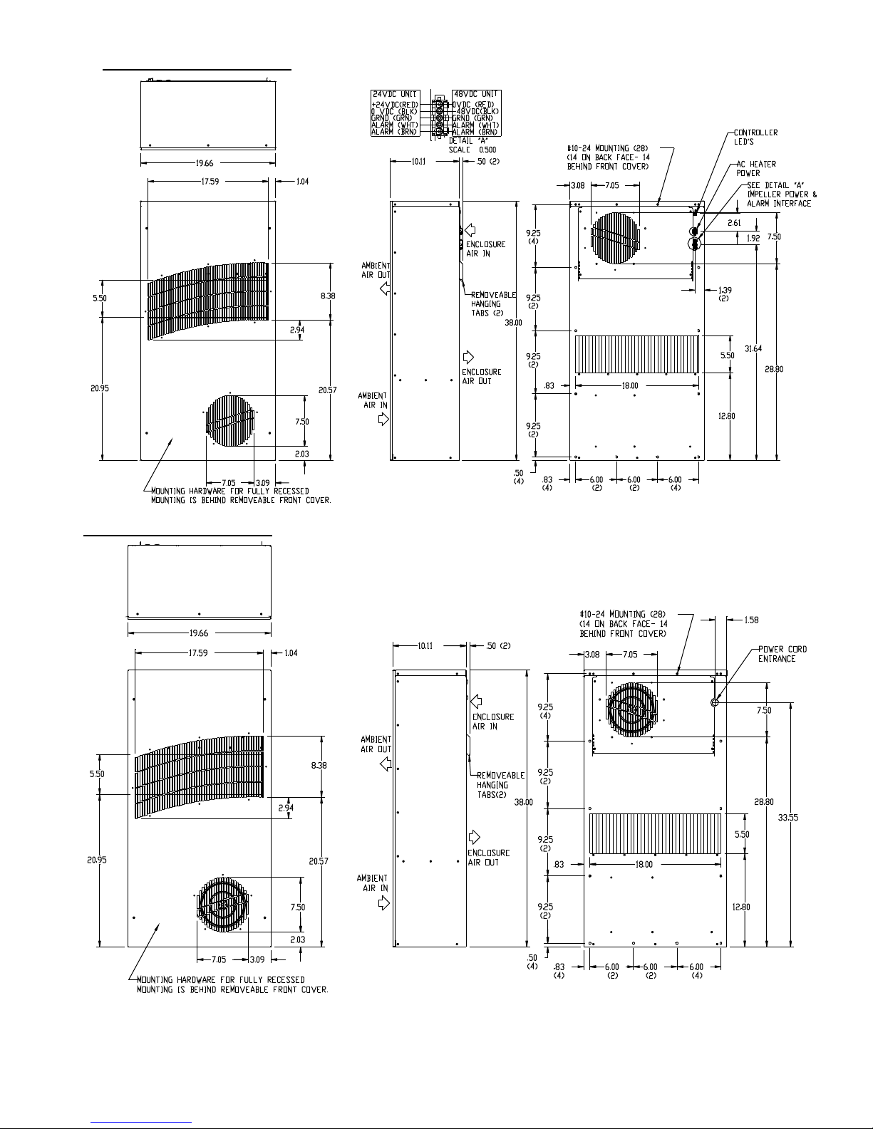
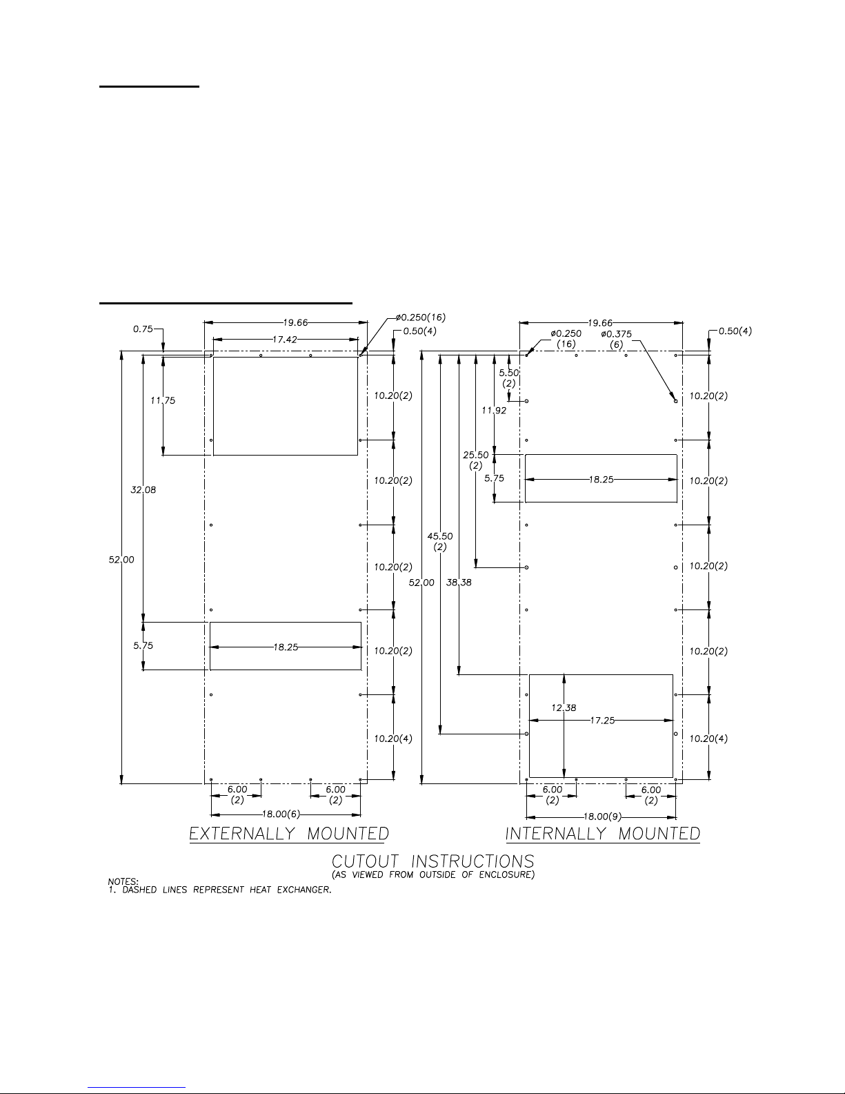
Design Data, Model Drawings ...............................................................................3-10
Mounting Instructions ............................................................................................3-10
Components List ....................................................................................................... 11
Wire Diagrams .......................................................................................................... 12
Trouble Shooting..................................................................................................13-14
NOTE: Some of the information in this manual may not apply if a special unit was ordered. If additional drawings
for a special unit are necessary, they have been inserted. Contact MAI if further information
is required.
RECEIVING THE HEAT EXCHANGER
Inspect the Heat Exchanger. Check for concealed damage that may have occurred during shipment. Look for dents,
scratches, loose assemblies, etc. Damage evident upon receipt should be noted on the freight bill. Damage should be
brought to the attention of the delivering carrier -- NOT to MAI- within 15 days of
delivery. Save the carton and packing material and request an inspection. Then file a claim with the delivering
carrier.
MAI cannot accept responsibility for freight damages; however, we will assist you in any
way possible.
TESTING THE HEAT EXCHANGER
TEST FOR FUNCTIONALITY BEFORE MOUNTING THE HEAT EXCHANGER TO THE ENCLOSURE.
Refer to nameplate for proper electrical current requirements, and then connect power cord to a properly grounded
power supply. Minimum circuit ampacity should be at least 125% of the amperage shown in the design data section
for the appropriate model. No other equipment should be connected to this circuit to prevent overloading.
Operate the heat exchanger for several minutes. No excessive noise or vibration should be evident during this run
period. Ambient air mover may not be energized at temperatures low enough to not require cooling. On DC powered
units air movers may not always be running at full speed.

Page 2 10-1008-221 Rev. 3
INSTALLATION
Step 1: Inspect heat exchanger. Verify functionality before mounting the heat exchanger, see Testing the Heat
Exchanger on page 1.
Step 2: Determine if the unit is to be surface or recess mounted. Using the appropriate cutout dimensions shown in
this manual, prepare the enclosure opening for either surface or recess mounting.
Step 3: Using the gasket kit provided, install gaskets to heat exchanger.
Step 4: Mount heat exchanger on enclosure using mounting screws provided. Torque screws to 25 in-lbs.
Step 6: Refer to unit nameplate for electrical requirements. Connect the power cord to a properly grounded power
supply. Use of an extension cord is not recommended. Electrical circuit should be fused with slow blow or HACR
circuit breaker.
PRINCIPLES OF OPERATION
Operating the heat exchanger below the minimum ambient temperature or above the maximum ambient
temperatures indicated on the nameplate voids all warranties.
It is recommended that the warranty section of this manual be read in order to familiarize you with parameters of
restricted operation.
MAINTENANCE
Air Movers
Air mover motors require no maintenance. All bearings are lubricated during manufacturing for the life of the motor.
If the ambient air mover should fail, it is not necessary to remove the heat exchanger from the cabinet or enclosure
to replace it. The ambient air mover is mounted on a bulkhead and is easily accessible by removing the front cover.
Caution: Operation of the heat exchanger in areas containing airborne caustics or chemicals can rapidly deteriorate
aluminum cores and air movers. Contact MAI for special recommendations.
Ambient Air In/Out Screens
In dirty environments the bug screens on the front cover may need to be cleaned periodically to maintain adequate
cooling performance. The front cover should be removed from the heat exchanger and set aside for cleaning with
water, air or scrubbed clean with a brush.

10-1008-221 Rev 3 Page 3
TX23 Series
25 Watts/°C (14 Watts/°F) H x W x D: 23" (584) x 12" (305) x 7.11" (181)
Full Max Min Shipping
Load Temp Temp Weight
Model Voltage Hz Amps Phase (°C/°F) (°C/°F) Lbs/Kgs
TX23-1424-XXX 24VDC 3.4 65/149 -40/-40 30/13.6
TX23-1448-XXX 48VDC 1.8 65/149 -40/-40 30/13.6
TX23-1416-XXX 115VAC 50/60 TBD 1 65/149 -40/-40 30/13.6
TX23-1426-XXX 230VAC 50/60 TBD 1 65/149 -40/-40 30/13.6
XXX will be replaced with a three-digit number designating all desired options. Consult the factory for specific model numbers.
TX23 Mounting Cutout Dimensions

Page 4 10-1008-221 Rev. 3
TX23 DC Model Drawing
TX23 AC Model Drawing

10-1008-221 Rev 3 Page 5
TX33 Series
50 Watts/°C (28 Watts/°F) H x W x D: 33" (838) x 15.66" (398) x 8.11" (206)
Full Max Min Shipping
Load Temp Temp Weight
Model Voltage Hz Amps Phase (°C/°F) (°C/°F) Lbs/Kgs
TX33-2824-XXX 24VDC 3.4 65/149 -40/-40 45/20.4
TX33-2848-XXX 48VDC 1.8 65/149 -40/-40 45/20.4
TX33-2816-XXX 115VAC 50/60 TBD 1 65/149 -40/-40 45/20.4
TX33-2826-XXX 230VAC 50/60 TBD 1 65/149 -40/-40 45/20.4
XXX will be replaced with a three-digit number designating all desired options. Consult the factory for specific model numbers.
TX33 Mounting Cutout Dimensions

Page 6 10-1008-221 Rev. 3
TX33 DC Model Drawing
TX33 AC Model Drawing

10-1008-221 Rev 3 Page 7
TX38 Series
100 Watts/°C (56 Watts/°F) H x W x D: 38" (965) x 19.66" (499) x 10.11" (257)
Full Max Min Shipping
Load Temp Temp Weight
Model Voltage Hz Amps Phase (°C/°F) (°C/°F) Lbs/Kgs
TX38-5624-XXX 24VDC 8.6 65/149 -40/-40 66/30
TX38-5648-XXX 48VDC 5.8 65/149 -40/-40 66/30
TX38-5616-XXX 115VAC 50/60 TBD 1 65/149 -40/-40 66/30
TX38-5626-XXX 230VAC 50/60 TBD 1 65/149 -40/-40 66/30
XXX will be replaced with a three-digit number designating all desired options. Consult the factory for specific model numbers.
TX38 Mounting Cutout Dimensions

Page 8 10-1008-221 Rev. 3
TX38 DC Model Drawing
TX38 AC Model Drawing

10-1008-221 Rev 3 Page 9
TX52 Series
150 Watts/°C (83 Watts/°F) H x W x D: 52" (1321) x 19.66" (499) x 10.11" (257)
Full Max Min Shipping
Load Temp Temp Weight
Model Voltage Hz Amps Phase (°C/°F) (°C/°F) Lbs/Kgs
TX52-8324-XXX 24VDC 21.1 65/149 -40/-40 100/45.3
TX52-8348-XXX 48VDC 7.8 65/149 -40/-40 100/45.3
TX52-8316-XXX 115VAC 50/60 4.3/6.7 1 65/149 -40/-40 100/45.3
TX52-8326-XXX 230VAC 50/60 2.2/3.4 1 65/149 -40/-40 100/45.3
XXX will be replaced with a three-digit number designating all desired options. Consult the factory for specific model numbers.
TX52 Mounting Cutout Dimensions

Page 10 10-1008-221 Rev. 3
TX52 DC Model Drawing
TX52 AC Model Drawing

10-1008-221 Rev 3 Page 11
TX23 Components List
Part NumberPart Description
24VDC 48VDC 115VAC 230VAC
Air Movers 10-1091-64 10-1091-55 12-1012-01 12-1012-02
Controller, Generic (may vary w/options) E117E004 E117E004 NA NA
Thermostat NA NA 10-1061-16 10-1061-16
Service Cord / Harness 09-3001-89 09-3001-89 52-6035-138 52-6035-139
TX33 Components List
Part NumberPart Description
24VDC 48VDC 115VAC 230VAC
Air Movers 10-1091-64 10-1091-55 10-1091-130 10-1091-131
Controller, Generic (may vary w/options) E117E004 E117E004 NA NA
Thermostat NA NA 10-1061-16 10-1061-16
Capacitors NA NA S-1353-1 52-6084-02
Service Cord / Harness 09-3001-89 09-3001-89 52-6035-138 52-6035-139
TX38 Components List
Part NumberPart Description
24VDC 48VDC 115VAC 230VAC
Air Movers 10-1091-12 10-1091-109 10-1091-132 10-1091-133
Controller, Generic (may vary w/options) E117E000 E117E000 NA NA
Thermostat NA NA 10-1061-16 10-1061-16
Capacitors NA NA 52-6031-03 52-6084-05
Service Cord / Harness 09-3001-89 09-3001-89 52-6035-138 52-6035-139
TX52 Components List
Part NumberPart Description
24VDC 48VDC 115VAC 230VAC
Air Movers 10-1091-125 10-1091-126 10-1091-134 10-1091-135
Controller, Generic (may vary w/options) E117E002 E117E006 NA NA
Thermostat NA NA 10-1061-16 10-1061-16
Capacitors NA NA 52-6031-03 52-6084-05
Service Cord / Harness 09-3001-96 09-3001-89 52-6035-138 52-6035-139

Page 12 10-1008-221 Rev. 3
TX DC Wire Diagram (see label on unit for actual options)
TX23 AC Wire Diagram (see label on unit for actual options)
TX33, TX38, TX52 AC Wire Diagram (see label on unit for actual options)

10-1008-221 Rev 3 Page 13
TROUBLE SHOOTING – AC Units
1. Check manufacturer’s nameplate located on the unit for correct power supply.
2. Unit blows fuses or breakers.
Under sized fuse/breaker or not time delayed.
Short in system.
3. Turn the power to the unit on. The enclosure air mover should come on. Is there airflow?
YES, proceed to step # 4.
NO, possible: Open motor winding
Stuckairmovermotor
Obstructed wheels/blades
4. Check thermostat setting? Adjust thermostat to the lowest setting. This should turn both air
movers on. Did both air movers come on when the thermostat was turned down?
YES, proceed to step #5.
NO, possible: Defective thermostat
5. Are both air movers running? If not the unit will not cool properly.
6. Check ambient air mover for airflow. Is there airflow?
YES, proceed to step # 7.
NO, possible: Defective thermostat
Open motor winding
Stuck air mover motor
Obstructed wheels/blades
7. To check for a bad thermostat. Turn power to the unit off. Remove access cover, place both
thermostat wires onto one terminal (replace access cover for safety). This will bypass the switch
in the thermostat. Turn the power on. If both air movers come on, the thermostat needs to be
replaced.
For additional technical information (i.e., amp draw, temperatures) contact
Replace part
Repair or Replace
defective part
Repair or Replace
defective part
Repair or Replace
defective part

Page 14 10-1008-221 Rev. 3
TROUBLE SHOOTING – DC Units
1. Check manufacturer’s nameplate located on the unit for correct power supply.
2. Unit blows fuses or breakers.
Under sized fuse/breaker or not time delayed.
Short in system.
3. Turn the power to the unit on.
4. Press the Quick-Test button (located above the LED’s on the enclosure side of the unit).
The unit will cycle through a series of self-diagnostic tests to verify proper operation of
components.
5. Do all LED’s clear to GREEN following the self test? RED indicates a fault.
YES, unit is working properly.
NO, identify which alarm is activated:
Note the Composite Alarm LED will also light if any other alarm activates.
RED Alarm LED Possible Cause Solution
Ambient air mover Open motor winding
OR Stuck air mover motor
Enclosure air mover Obstructed blades
Hi / Lo Temp If the enclosure temperature is outside the nameplate
temperature range, the Hi / Lo Temp alarm will activate.
Composite Alarm Only Controller Temperature Sensor Failure
For additional technical information (i.e., amp draw, temperatures) contact
Repair or Replace
defective part
Quick Test Button
Composite Alarm LED
Ambient Fan LED
Hi / Lo TempLED
Enclosure Fan LED
Quick Test Button
Repair or Replace
defective part
Repair or Replace
defective part

McLean Cooling Technology
11611 Business Park Blvd N
Champlin, MN 55316 USA
Tel 763-323-8200
Fax 763-576-3200
www.McLeanParts.net
P
rotecting E
l
ectronics.
Exceeding Expectations.
™
©2008 McLean Midwest Corporation
This manual suits for next models
3
Table of contents
Other McLean Air Conditioner manuals

McLean
McLean ProAir CR43 User manual

McLean
McLean SPECTRACOOL G57 User manual

McLean
McLean T20 User manual

McLean
McLean SPECTRACOOL G57 User manual

McLean
McLean T43 User manual

McLean
McLean HB16 Series User manual

McLean
McLean T62 User manual

McLean
McLean T15 User manual

McLean
McLean T50 User manual

McLean
McLean ProAir CR29 User manual