McLean SPECTRACOOL G57 User manual

© 2012 Pentair Technical Products 89055585
Rev. I P/N 10-1008-243
Protecting Electronics.
Exceeding Expectations.™
McLean Parts
5736 N Michigan Road
Indianapolis, IN 46228 USA
+1.317.257.6811
+1.317.257.1590
McLeanParts.com
INSTRUCTION MANUAL
SPECTRACOOL™
Air Conditioner
G57

© 2012 Pentair Technical Products 89055585
- 2 -
TABLE OF CONTENTS
RECEIVING THE AIR CONDITIONER ......................................................................................................................................................................................................................................................................... 3
HANDLING AND TESTING THE AIR CONDITIONER ............................................................................................................................................................................................................................................ 3
HOW TO READ MODEL NUMBERS .......................................................................................................................................................................................................................................................................... 3
TECHNICAL INFORMATION........................................................................................................................................................................................................................................................................................ 4
Sequence of Operation ...................................................................................................................................................................................................................................................................................4
Heating ......................................................................................................................................................................................................................................................................................................4
Cooling ...................................................................................................................................................................................................................................................................................................... 4
Standard and Optional Component Operation .....................................................................................................................................................................................................................................4
Thermostat .............................................................................................................................................................................................................................................................................................. 4
Remote Access Control (optional) ...................................................................................................................................................................................................................................................4
Head Pressure Control ......................................................................................................................................................................................................................................................................... 4
Contactor..................................................................................................................................................................................................................................................................................................4
Freezestat ................................................................................................................................................................................................................................................................................................. 4
Time Delay Relay ................................................................................................................................................................................................................................................................................... 5
200 V to 230 V Transformer (G572026G2XX only) ...................................................................................................................................................................................................................... 5
Phase Monitor (G572046GXXX only) .............................................................................................................................................................................................................................................. 5
460 V to 230 V Transformer (G572046GXXX only) .....................................................................................................................................................................................................................5
230V to 10V Transformer (optional) ................................................................................................................................................................................................................................................5
230V to 24V Transformer and Relay (optional) ........................................................................................................................................................................................................................... 5
Schematics and Wiring Diagrams for Thermostat Control .................................................................................................................................................................................................................5
G57 208V 1-Phase Generic Schematic (actual unit options may vary) ..............................................................................................................................................................................5
G57 230V 1-Phase Generic Schematic (actual unit options may vary) ..............................................................................................................................................................................6
G57 400/460V 3-Phase Generic Schematic (actual unit options may vary) ..................................................................................................................................................................... 6
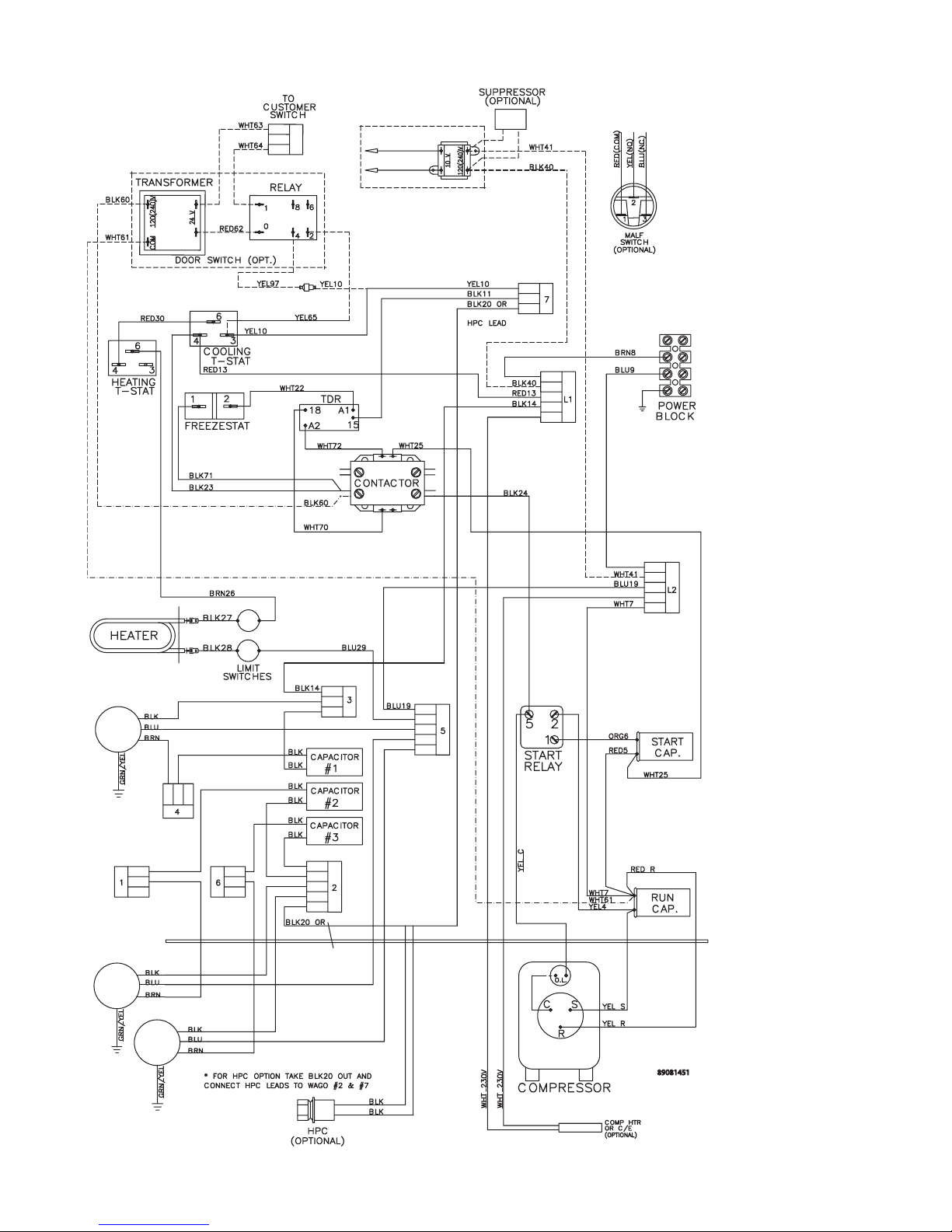
G57 208V 1-Phase Generic Wire Diagram (actual unit options may vary) ........................................................................................................................................................................7
G57 230V 1-Phase Generic Wire Diagram (actual unit options may vary) ........................................................................................................................................................................8
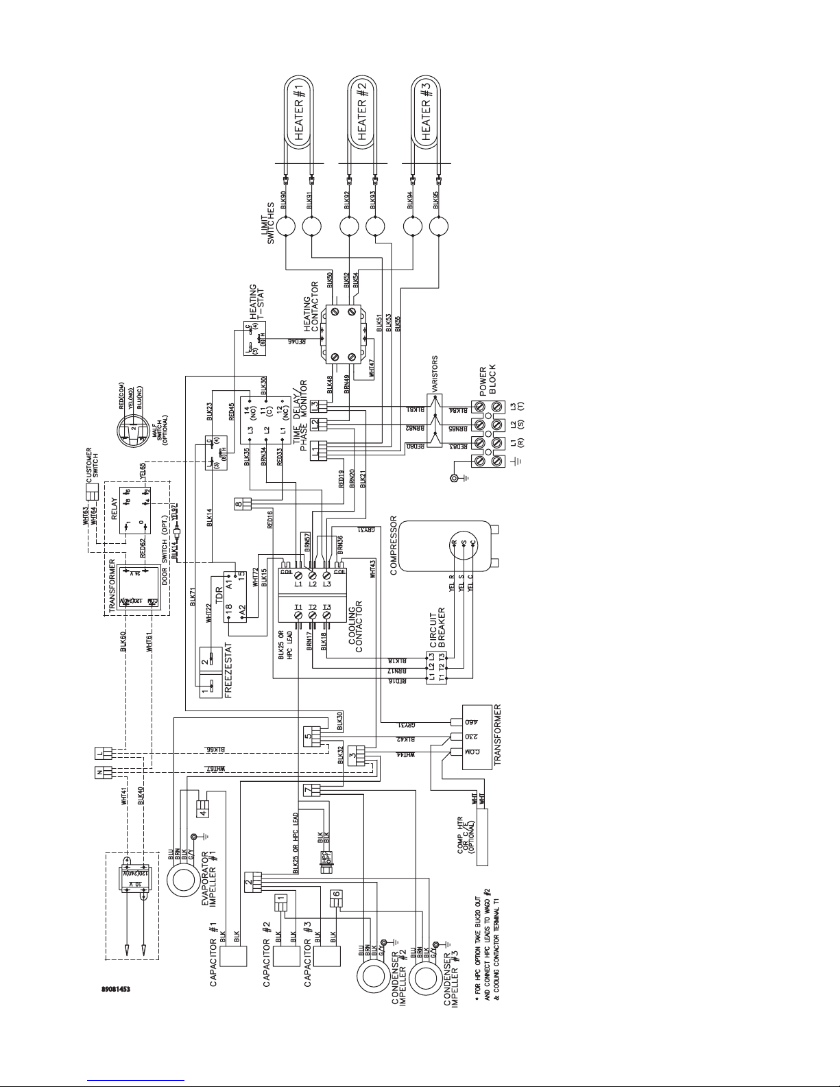
G57 400/460V 3-Phase Generic Wire Diagram (actual unit options may vary) ............................................................................................................................................................... 9
DIMENSIONAL DRAWINGS ......................................................................................................................................................................................................................................................................................10
20000 BTU/Hr. (G572026GXXX, G572026G2XX) With Thermostats ..............................................................................................................................................................................................10
20000 BTU/Hr. (G572046G15X) With Thermostats ..............................................................................................................................................................................................................................10
INSTALLATION INSTRUCTIONS ...............................................................................................................................................................................................................................................................................11
REMOTE ACCESS CONTROL (optional) ................................................................................................................................................................................................................................................................13
INTRODUCTION ...............................................................................................................................................................................................................................................................................................13
ENERGIZING THE CONTROLLER .................................................................................................................................................................................................................................................................13
CONTROL STATUS INDICATION ..................................................................................................................................................................................................................................................................13
DISPLAYING AND CHANGING PROGRAM VARIABLES ........................................................................................................................................................................................................................14
OPERATING PARAMETERS ............................................................................................................................................................................................................................................................................14
ALARM PARAMETERS .....................................................................................................................................................................................................................................................................................14
DISPLAYING TEMPERATURE SENSOR #2 ..................................................................................................................................................................................................................................................14
COMPRESSOR RESTART TIME DELAY ........................................................................................................................................................................................................................................................14
ALARM OUTPUT CONTACT ..........................................................................................................................................................................................................................................................................14
ALARM INPUT CONNECTION ......................................................................................................................................................................................................................................................................15
ALARM CONDITION DISPLAY ......................................................................................................................................................................................................................................................................15
AIR CONDITIONER UNIT COMMUNICATION FEATURES .....................................................................................................................................................................................................................15
USB Communication ..........................................................................................................................................................................................................................................................................15
Ethernet Communication .................................................................................................................................................................................................................................................................15
Software and MIB File Downloads ................................................................................................................................................................................................................................................15
Using the McLean PC Interface Tool .............................................................................................................................................................................................................................................15
USB COMMUNICATION MODE ...................................................................................................................................................................................................................................................................16
Viewing Air Conditioner Unit Values ............................................................................................................................................................................................................................................16
Changing Air Conditioner Unit Values .........................................................................................................................................................................................................................................16
Viewing and Changing Ethernet Information ...........................................................................................................................................................................................................................16
ETHERNET COMMUNICATION MODE .......................................................................................................................................................................................................................................................17
Viewing Air Conditioner Unit Values ............................................................................................................................................................................................................................................17
Changing Air Conditioner Unit Values .........................................................................................................................................................................................................................................17
Viewing and Changing Ethernet Information ...........................................................................................................................................................................................................................17
Alarm Log Accessible with SNMP ..................................................................................................................................................................................................................................................17
Remote Access Control Pin-out .................................................................................................................................................................................................................................................................18
Schematic and Wiring Diagram for Remote Access Control ...........................................................................................................................................................................................................19
G57 1-Phase Generic Schematic (actual unit options may vary) .......................................................................................................................................................................................19
G57 3-Phase Generic Schematic (actual unit options may vary) .......................................................................................................................................................................................20
G57 1-Phase Generic Wire Diagram for Remote Access Control (actual unit options may vary) ...........................................................................................................................21
G57 3-Phase Generic Wire Diagram for Remote Access Control (actual unit options may vary) ...........................................................................................................................22
DIMENSIONAL DRAWINGS ......................................................................................................................................................................................................................................................................................23
G57 Generic Model Drawing With Remote Access Control .............................................................................................................................................................................................................23
INSTALLATION INSTRUCTIONS WITH REMOTE ACCESS CONTROL ............................................................................................................................................................................................................24
MAINTENANCE ............................................................................................................................................................................................................................................................................................................25
Compressor .......................................................................................................................................................................................................................................................................................................25
Inlet Air Filter ....................................................................................................................................................................................................................................................................................................25
How To Remove, Clean or Install a New Inlet Air Filter ......................................................................................................................................................................................................................25
Condenser and Evaporator Air Movers ...................................................................................................................................................................................................................................................26
Refrigerant Loss ...............................................................................................................................................................................................................................................................................................26
Refrigerant Properties Chart (R407c) .......................................................................................................................................................................................................................................................27
Functional Data ...............................................................................................................................................................................................................................................................................................27
Unit Characteristics ........................................................................................................................................................................................................................................................................................28
SERVICE DATA...............................................................................................................................................................................................................................................................................................................29
Components List .............................................................................................................................................................................................................................................................................................29
TROUBLE SHOOTING .................................................................................................................................................................................................................................................................................................30
Basic Air Conditioning Trouble Shooting Check List - Thermostat Version................................................................................................................................................................................30
Symptoms and Possible Causes - Thermostat Version ......................................................................................................................................................................................................................31
Basic Air Conditioning Trouble Shooting Check List - Remote Access Control Version ........................................................................................................................................................32
Symptoms and Possible Causes - Remote Access Control Version ...............................................................................................................................................................................................33

© 2012 Pentair Technical Products89055585 - 3 -
RECEIVING THE AIR CONDITIONER
Inspect the air conditioner. Check for concealed damage that may have occurred during shipment. Look for dents,
scratches, loose assemblies, evidence of oil, etc. Damage evident upon receipt should be noted on the freight bill.
Damage should be brought to the attention of the delivering carrier -- NOT to McLean Parts -- within 15
days of delivery. Save the carton and packing material and request an inspection. Then le a claim with the delivering
carrier.
McLean Parts cannot accept responsibility for freight damages; however, we will assist you in any way
possible.
HANDLING AND TESTING THE AIR CONDITIONER
If the air conditioner has been in a horizontal position, be certain it is placed in an upright, vertical or mounting
position for a minimum of ve (5) minutes before operating.
Do not attempt to operate the air conditioner while it is horizontal
or on its side, back or front. The refrigeration compressor is lled
with lubricating oil. This will cause permanent damage to the air
conditioner and also voids the warranty.
CAUTION
TEST FOR FUNCTIONALITY BEFORE MOUNTING THE AIR CONDITIONER TO THE ENCLOSURE.
Refer to the nameplate for proper electrical current requirements, and then connect the power cord to a properly
grounded power supply. Minimum circuit ampacity should be at least 125% of the amperage shown in the design
data section for the appropriate model. No other equipment should be connected to this circuit to prevent
overloading.
Immediately after applying power, the evaporator blower (enclosure air) should start running. Operate the air
conditioner with the compressor running for ve (5) to ten (10) minutes. You will need to set the cooling thermostat or
controller setpoint below the ambient temperature to operate the compressor.
Condenser air temperatures should be warmer than normal room temperatures within a few minutes after the
condenser impellers start.
See Sequence of Operation on page 4 for specics on how the unit operates when powered up.
HOW TO READ MODEL NUMBERS
G57 20 2 6 G150
12345
1. Identies the type/family of air conditioner and the approximate height (i.e. G57 = Global family about 57
inch high).
2. This is the air conditioner’s listed capacity in BTU/Hr. at rated conditions. (i.e. 20 = 20,000 BTU/Hr. at
131/131 F)
3. 2 = 208 or 230 Volt, 4 = 460 Volt.
4. 6 = 50/60 Hz or 60 Hz only.
5. Unique set of numbers for each air conditioner which identies the accessories on a model. All G2XX
models are 208 Volt 60 Hz.

© 2012 Pentair Technical Products 89055585
- 4 -
TECHNICAL INFORMATION
Sequence of Operation
The air conditioner comes standard with two internally mounted thermostats. There are two modes of operation;
heating and cooling. During heating and cooling modes, the evaporator fan will be running.
Heating
When the enclosure temperature is below the heating thermostat setpoint, power is applied to the heaters.
When the enclosure temperature is 10 degrees above the setpoint, the heater is powered o.
Cooling
When the enclosure temperature is above the cooling thermostat setpoint, power is applied through the
thermostat. The compressor is then energized either directly or through a contactor if unit requires one. The
condenser impellers will start immediately if the unit is not equipped with an optional head pressure control
switch. If the unit is equipped with an optional head pressure control switch, the condenser impellers will
start once the refrigerant pressure reaches the setting of the switch. Component specic information is listed
below.
Operating the air conditioner below the minimum ambient temperature or above the maximum ambient
temperatures indicated on the nameplate voids all warranties. DO NOT set the enclosure thermostat to a
temperature lower than 70 F. Doing so can increase the likelihood of frost buildup on the evaporator coil.
The moisture that the enclosure air can contain is limited. If moisture ows from the drain tube continuously
this can only mean that ambient air is entering the enclosure. Be aware that frequent opening of the
enclosure’s door admits humid air that the air conditioner must then dehumidify.
Standard and Optional Component Operation
Thermostat
The G57 air conditioner uses our standard 10-1061-16 thermostat. The thermostat setpoint equals the
temperature that the air conditioner turns o. The thermostat has a 10 F dierential from setpoint until it calls
for cooling or heating. An example of operation is shown below.
For cooling (75-100 F range):
• Thermostat setpoint = 80 F
• Cooling turns on at 90 F
• Cooling turns o at 80 F
For heating (55-65 F range):
• Thermostat setpoint = 55 F
• Heating turns on at 55 F
• Heating turns o at 65 F
NOTE: For testing purposes only, the thermostat stop screw may be removed (on units so
equipped) to allow settings below 70 F. After testing, replace the stop screw and verify that the
thermostat cannot be set below 70 F. Extended operation below 70 F can cause coil freeze ups
resulting in reduced load and/or unit damage.
Remote Access Control (optional)
See REMOTE ACCESS CONTROL (optional) on page 13
Head Pressure Control
Unit is set at the factory, no adjustment necessary.
At a saturated condenser temperature of 82 F (170 psig), the condenser fans will power o. At a saturated
condenser temperature of 104 F (246 psig), the condenser fans will power on.
Contactor
The contactor on this model uses a 230V coil.
Freezestat
The freezestat shuts down the compressor during a frozen evaporator coil condition. The freezestat will
automatically reset when the frozen coil has thawed suciently.

© 2012 Pentair Technical Products89055585 - 5 -
Time Delay Relay
The time delay relay keeps the unit from short cycling after the freezestat resets following a frozen evaporator
coil condition.
200 V to 230 V Transformer (G572026G2XX only)
The 230 V from this transformer powers the compressor, fans, contactor and optional transformers.
Phase Monitor (G572046GXXX only)
The phase monitor protects the compressor from reverse operation. When both lights on the monitor are lit
constant, the power to the unit has been wired correctly and the compressor will operate as designed.
If both lights on the monitor are not lit constant, the unit is out of phase. Swap the power leads at the terminal
block until both lights are lit constant.
Factory Settings:
Top dial set at 480 V for 60 Hz operation (Reset to 440 V for 50 Hz operation)
Middle dial set at 5 seconds
Bottom dial set at -20%
460 V to 230 V Transformer (G572046GXXX only)
The 230 V from this transformer powers the fans, contactor and optional transformers. 460 V is only used to
run the compressor.
230V to 10V Transformer (optional)
This transformer powers the thermal display only.
230V to 24V Transformer and Relay (optional)
This transformer and relay are used to start/stop the unit thru a customer supplied, remote mounted door
switch.
Schematics and Wiring Diagrams for Thermostat Control
G57 208V 1-Phase Generic Schematic (actual unit options may vary)
89044386

© 2012 Pentair Technical Products 89055585
- 6 -
G57 230V 1-Phase Generic Schematic (actual unit options may vary)
89047070
G57 400/460V 3-Phase Generic Schematic (actual unit options may vary)
MTR
MTR
MTR
MTR
CIRCUIT
BREAKER
CONTACTOR
MONITOR
PHASE
R
L1 L2
S
L3
T
AUTO-TRANSFORMER
COMPRESSOR
CLG CONTACTOR
CLG TSTAT
PHASE MONITOR
EVAPORATOR
CONDENSER
CONDENSER
IMPELLER 2
IMPELLER 1
IMPELLER
CAP
CAP
CAP
GRND
RELAY
HPC
COOLING CONTACTOR
HEATING
LIMIT SWT'S
AUTO & MAN
HEATERS
HTG TSTAT
HTG CONTACTOR
FREEZE STAT
VARISTOR
TRANSFORMER W/
TEMP. DISPLAY
(OPTIONAL)
DOOR SWITCH
TRANSFORMER
RELAY (OPTION)
TDR
24V
RSWT.
CUST.
R
89060233

© 2012 Pentair Technical Products89055585 - 7 -
G57 208V 1-Phase Generic Wire Diagram (actual unit options may vary)

© 2012 Pentair Technical Products 89055585
- 8 -
G57 230V 1-Phase Generic Wire Diagram (actual unit options may vary)

© 2012 Pentair Technical Products89055585 - 9 -
G57 400/460V 3-Phase Generic Wire Diagram (actual unit options may vary)

© 2012 Pentair Technical Products 89055585
- 10 -
DIMENSIONAL DRAWINGS
20000 BTU/Hr. (G572026GXXX, G572026G2XX) With Thermostats
$&&(66+2/(72
>@2''5$,1678%
&/($1$%/(5(86$%/(
$/80,180,1/(7),/7(5
%(+,1'5(029$%/(3$1(/
(1&/2685(
$,5,1
$0%,(17
$,5,1
:$50
$,5287
5(029$%/(
+$1*,1*
7$%6
&22/
$,5287
127(
$33529(727<3(5;
02817,1**$6.(76833/,('1276+2:1
$&&(663$1(/)25
237,21$/+($7(5
81&
02817,1*+2/(6
32:(5,1/(7
&22/,1*
7+(50267$7
+($7
7+(50267$7
237,21$/
88040022
20000 BTU/Hr. (G572046G15X) With Thermostats
$&&(663$1(/
)25+($7(5
81&
02817,1*+2/(6
32:(5,1/(7
&22/,1*
7+(50267$7
+($7
7+(50267$7
$&&(66+2/(72
2''5$,1678%
&/($1$%/(5(86$%/(
$/80,180,1/(7),/7(5
%(+,1'5(029$%/(3$1(/
127(
$33529(727<3(5
02817,1**$6.(76833/,('1276+2:1
(1&/2685(
$,5,1
$0%,(17
$,5,1
:$50
$,5287
5(029$%/(
+$1*,1*
7$%6
&22/
$,5287
89059779

© 2012 Pentair Technical Products89055585 - 11 -
INSTALLATION INSTRUCTIONS
1. Inspect the air conditioner and verify correct functionality before mounting the air conditioner. See
HANDLING AND TESTING THE AIR CONDITIONER on page 3.
2. Using the mounting gasket kit provided with the unit, install gaskets to the air conditioner, see Figure 1.
3. Mount air conditioner on enclosure taking care not to damage the mounting gasket. The mounting gasket
is the seal between the air conditioner and the enclosure. Avoid dragging the air conditioner on the
enclosure with the mounting gasket attached as this could cause rips or tears in the gasket and risk losing
the water tight seal.
4. Allow unit to remain upright for a minimum of ve (5) minutes before starting. CAUTION! Air conditioner
must be in upright position during operation.
5. Refer to the nameplate for electrical requirements. Wire the unit to a properly grounded power supply.
Electrical circuit should be fused with slow blow or HACR circuit breaker.
6. Some air conditioners require a remote mounted thermostat. Wire the thermostat outputs to the
appropriate terminals on the 24 VAC terminal strip by noting the locations on the correct wiring diagram.
7. Set thermostat for required cabinet temperature. Refer to Sequence of Operation on page 9 for thermostat
adjustment and operation.
88028328 89061034
SURFACE MOUNT SURFACE MOUNT (3-PHASE VOLTAGE)

© 2012 Pentair Technical Products 89055585
- 12 -
89045267
PARTIAL RECESS MOUNT
Figure 1
Cutout Dimensions

© 2012 Pentair Technical Products89055585 - 13 -
REMOTE ACCESS CONTROL (optional)
INTRODUCTION
The McLean Remote Access Control is a parametric controller for the complete management of McLean air
conditioners. All settings are pre-programmed at the factory. Cooling/heating set-points, cooling/heating dierential
and high /low temperature alarm set-points can be adjusted by the user. Alarms are outputted through a relay contact
and also can be accessed through an Ethernet connection utilizing SNMP. A USB connection is also provided and can
be used to interface with the controller utilizing ModBus.
ENERGIZING THE CONTROLLER
The controller is wired and programmed at the factory to be energized when power is supplied to the air conditioner.
CONTROL STATUS INDICATION
The display has numerous symbols that indicate if the controller is heating, cooling, alarming, if the compressor is
enabled, and if the ambient fan is enabled. The 3 alpha-numeric characters further describe alarms and show the
cabinet temperature by default.
SYMBOL COLOR ICON ON ICON FLASHING
1 AMBER Compressor On Start-up Request
2,3,4 AMBER Not Used Not Used
A AMBER Compressor On Not Used
B AMBER Evaporator Fan On Start-up Request
C AMBER Not Used Not Used
D AMBER Not Used Not Used
E AMBER Heater Active Not Used
F RED Alarm Active Not Used
G AMBER Controller Active Not Used
H AMBER Not Used Not Used

© 2012 Pentair Technical Products 89055585
- 14 -
DISPLAYING AND CHANGING PROGRAM VARIABLES
Access: To view and/or change parameters, press and hold the Prg and Sel buttons for greater than 5 seconds. Press
the up or down arrow buttons until “22” is displayed, then press Sel button. When “S-P” is displayed, press Sel.
Navigation: Press up or down arrows to display sub-menus then press Sel to select the desired sub-menu. In the sub-
menu, use up or down arrows to display parameters for viewing or changing and press Sel. Use Prg button to back out
of menu levels as desired.
Adjust: Use the up or down arrows to change the parameter value then push Sel to save that setting. If Sel is not
pressed, the change to the value will not be saved. Navigate to and change other parameters as desired. When
nished, push Prg to back out of the sub-menus to the main menu.
NOTE: The display will revert to normal temperature display mode if no buttons are pressed for
60 seconds.
OPERATING PARAMETERS
Parameter Default Value Range Description
r01 80 F 72 F to 120 F Cooling set-point
r02 7 F - Cooling dierential
A04 50 F* 32 F to 60 F Heating set-point*
A05 7 F* - Heating dierential*
Cooling turns on at r01 + r02, and o at r01
Heating turns on at A04, and o at A04 + A05
*Functional only on units with heater option
ALARM PARAMETERS
Parameter Default Value Description
P16 125 F High Temperature Alarm
P19 40 F Low Temperature Alarm
DISPLAYING TEMPERATURE SENSOR #2
Sensor number 2, the air outlet or condenser coil sensor, can be viewed at any time by pressing the up or down arrow
button on the front panel of the controller display. The display will revert to displaying temperature sensor number 1
(the AC inlet temperature) after 60 seconds. Both sensors can also be read through the Ethernet and USB connections.
COMPRESSOR RESTART TIME DELAY
A factory set 6 minute (360 second) restart delay exists to reduce residual back pressure before allowing the
compressor to restart. The compressor will stay o for the entire restart duration after the compressor is disabled. A
ashing “1” on the controller display will indicate the unit is in a compressor restart delay while calling for cooling.
ALARM OUTPUT CONTACT
The McLean Remote Access Control has a normally open dry contact alarm output with a resistive load rating of 250
VAC at 3 amps. Two yellow 18 AWG wires located at the back of the air conditioner provide a connection to this output.

© 2012 Pentair Technical Products89055585 - 15 -
ALARM INPUT CONNECTION
The McLean Remote Access Control can accept a dry contact/switch input via the two 18 AWG white wires located at
the back of the air conditioner. This input is associated with the controller display alarm mnemonic TP (door open and/
or smoke detected). [To use this feature, remove the splice connector connecting the two white wires and connect
customer supplied enclosure door switch in its place.]
ALARM CONDITION DISPLAY
There are seven possible non-latching alarm conditions detectable by the controller and are indicated on the
controller display. All alarms can also be accessed through the Ethernet and USB connections.
Alarm Mnemonic Description Cause Result Alarm Relay
TP General Alarm Door open and/or smoke
detected
Unit turns o for duration
of alarm Relay Contacts Close
LA High Pressure Warning MALF high pressure
switch opens No eect on function N/A
E1 Air Inlet Temperature
Sensor Alarm Sensor Failure Unit turns o for duration
of alarm Relay Contacts Close
E2 Air Outlet Temperature
Sensor Alarm Sensor Failure Unit turns o for duration
of alarm Relay Contacts Close
Ht High Temperature Alarm
Default = 125 F
Cabinet over temperature
Alarm clears at default
setting -2 F
No eect on function Relay Contacts Close
Lt Low Temperature Alarm
Default = 40 F
Cabinet under
temperature
Alarm clears at default
setting +27 F
No eect on function Relay Contacts Close
A1 Frost Alarm Evaporator coil frozen
Alarm clears at 59 F
Compressor and
Evaporator fan o for
duration of alarm
Relay Contacts Close
AIR CONDITIONER UNIT COMMUNICATION FEATURES
Air conditioner units equipped with communication capabilities provide both SNMP protocol through
Ethernet and ModBus protocol via USB. McLean has a PC Interface Tool available for download that can utilize
either mode to communicate with the air conditioner unit.
USB Communication
This communication mode allows direct connection of a PC to the air conditioner unit. The protocol supported
is ModBus. Use the McLean PC Interface Tool to communicate with the air conditioner unit. A MINI-b USB
connection is provided.
Ethernet Communication
This communication mode allows remote connection to the air conditioner unit protocol supported by SNMP.
Customers can use their own software with the provided MIB le, or use the McLean PC Interface Tool to
communicate with the air conditioner unit. An RJ45 connection is provided.
Note: ACU has a default IP Address of 192.168.1.2
Both Ethernet and USB communication modes allow the ability to:
• Read ACU inlet and outlet air temperatures
• Read and change Cooling Set-point and Cooling Dierential
• Read and change Heating Set-point, Heating Dierential
• Read and change High and Low Temperature Alarm Settings
• Read and change Gateway IP Address, Device IP Address, Subnet Mask, Trap IP Address and Community
• Read and change Unit Identication
• Read and change the state of IP addressing (static or dynamic)
• Read current Alarm Status
Software and MIB File Downloads
The McLean PC Interface Tool and the SNMP MIB le can be downloaded from www.mcleancoolingtech.com
or www.homanonline.com.
Using the McLean PC Interface Tool

© 2012 Pentair Technical Products 89055585
- 16 -
The PC Interface Tool gives the user the ability to communicate with the air conditioner unit to read/write
parameters using either Ethernet or USB connections.
USB COMMUNICATION MODE
NOTE: Before connecting unit to the PC, make note of the comm ports present. After the unit is
connected to the PC, a new comm port will be added to the list. Use this new comm port.
• From Tools menu select Use Ethernet
• When Use Ethernet is unchecked, then Comm Port menu is enabled, Device IP and Community boxes are not shown,
and USB communication can be used
• To set the comm port, choose Comm Port from the Tools menu and then select the comm port from the combo box
Viewing Air Conditioner Unit Values
To view Air Conditioner Unit values
• Select the ACU Values tab
• Select the Enable Comm button (the PC Interface will now be communicating with unit)
• To stop communication select the Disable Comm button
Changing Air Conditioner Unit Values
To change ACU Values
• Select the Settings tab
• Select the value to change
• Make the change to the value
• Select the Change Setting button
• Change can be veried in ACU Values tab
Viewing and Changing Ethernet Information
To view and change Ethernet Information
• Select Ethernet Info tab
To view Ethernet Information
• Click Read Ethernet Info button
To change to dynamically assigning IP Address Mode
• Check Use DHCP Server checkbox
• Enter Trap IP Address and Community
• Click Load Ethernet Info button
To change to statically assigning IP Address Mode
• Uncheck Use DHCP Server checkbox
• Enter Device IP Address, Subnet Mask, Gateway IP Address, Trap IP Address and Community
• Click Load Ethernet Info button

© 2012 Pentair Technical Products89055585 - 17 -
ETHERNET COMMUNICATION MODE
• From Tools menu select Use Ethernet
• When Use Ethernet is checked, Comm Port selection is disabled, Device IP and Community boxes are shown and
Ethernet communication can be used.
• Enter unit’s IP Address and Community string in Device IP and Community boxes at the bottom of the PC Interface Tool.
Each unit has two community strings. One is a Read/Write community string (defaulted to
‘private’) that can be changed by the customer (must be 4 to 8 characters long). The other is a
Read-Only community string (‘public’) and cannot be changed.
Viewing Air Conditioner Unit Values
To view Air Conditioner Unit values
• Select the ACU Values tab
• Select the Enable Comm button (the PC Interface will now be communicating with unit)
• To stop communication select the Disable Comm button
Changing Air Conditioner Unit Values
To change ACU Values
• Select the Settings tab
• Select the value to change
• Make the change to the value
• Select the Change Setting button
• Change can be veried in ACU Values tab
Viewing and Changing Ethernet Information
To view and change Ethernet Information
• Select Ethernet Info tab
To view Ethernet Information
• Click Read Ethernet Info button
To change to dynamically assigning IP Address Mode
• Check Use DHCP Server checkbox
• Enter Trap IP Address and Community
• Click Load Ethernet Info button
To change to statically assigning IP Address Mode
• Uncheck Use DHCP Server checkbox
• Enter Device IP Address, Subnet Mask, Gateway IP Address, Trap IP Address and Community
• Click Load Ethernet Info button
Alarm Log Accessible with SNMP
• Using custom software with McLean provided MIB le gives the ability to view a log of the last 25 alarms

© 2012 Pentair Technical Products 89055585
- 18 -
Remote Access Control Pin-out
FUNCTION NAME PIN # WIRE #
U1 OUTPUTS
COOL No1 1 ORG78
C1/2 2 BLK
HEAT No2 7 BRN76
C1/2 3 BLK
ENCL MI No3 8 BLK77
C3/4 4 BLK
NA No4 (na) 9 BLK
C3/4 10 BLK
ALARM RELAY OUTPUT No5 12 YEL39
C5 6 YEL38
NA x 5 NA
NA x 11 NA
U2 INPUTS
ALARM INPUT CONNECTION ID1 8 WHT63
MALFUNCTION NC SWITCH ID2 1 BLU88
NA ID3 (na) 9 BLU
NA ID4 (na) 2 BLU
NA ID5 (na) 10 BLU
DIGITAL INPUT GROUND ID GND 3 BLU
NA Y (na) 4 NA
NA GND (na) 5 NA
T1, EVAP IN THERMISTOR B1 13 RED
T2, EVAP OUT THERMISTOR B2 12 RED
T1, T2 GND GND 6 WHT
NA B3 11 NA
CONTROLLER POWER G 7 BLK40
CONTROLLER POWER G0 14 WHT41
U3 DATA
POWER 1 RED
GROUND 2 BLACK
DIRECTION 3 GREEN
DATA 4 WHITE

© 2012 Pentair Technical Products89055585 - 19 -
Schematic and Wiring Diagram for Remote Access Control
G57 1-Phase Generic Schematic (actual unit options may vary)
89080129

© 2012 Pentair Technical Products 89055585
- 20 -
G57 3-Phase Generic Schematic (actual unit options may vary)
89080130
Other manuals for SPECTRACOOL G57
1
Table of contents
Other McLean Air Conditioner manuals

McLean
McLean HB16 Series User manual

McLean
McLean TX23-1424 SERIES User manual

McLean
McLean T43 User manual

McLean
McLean SPECTRACOOL G57 User manual

McLean
McLean T15 User manual

McLean
McLean T50 User manual

McLean
McLean ProAir CR29 User manual

McLean
McLean T15-0116-GXXX Series User manual

McLean
McLean T62 User manual

McLean
McLean SPECTRACOOL G52 1-Phase User manual