MCW HIB0150EN200V User manual

HIB Enclosed Inverter User Guide
(0.75kW~37
kW)
V1.
3
.

HIB Enclosed Inverter User Guide
Contents
1 Safety information ................................................................................ 1
2 Technical Data ...................................................................................... 2
3 Motor Connection ................................................................................ 4
4 Operation ............................................................................................. 5
5 Single phase circuit diagram ................................................................ 7
6 Three phase circuit diagram ................................................................. 8
www.motorcontrolwarehouse.co.uk
Copyright © Motor Control Warehouse October 2017
Re ision V1.3.2
HIB Enclosed Inverter User Guide
P a g e | 1
1
Safety Information
Safety Information
This chapter provides very important information so that you can use the HIB Enclosed Inverter safely, prevent
injury or death, or damage to equipment. Please read this information thoroughly and make sure you observe
all the safety information shown below and elsewhere in this manual and in the HD 00 Easy Start Guide.
Please make this User Guide and the HD 00 Easy Start Guide available for the end user.
Please read this safety information in conjunction with the safety information in the HEDY HD 00 Easy Start
Guide. Please read the HEDY HD 00 Easy Start Guide for details such as Fuse/MCB and cable sizes etc.
Safety symbols
•The HIB Enclosed Inverter should ONLY be installed, commissioned and maintained by ualified and
competent personnel.
•The HIB must be installed to the latest IEE wiring regulations taking into account local regulations.
•Before power is applied to the HIB, ensure the HIB cubicle door is closed.
•Dangerous voltages are present when the input power supply is connected to the HIB. Before attempting
any work on the HIB cubicle or motor, isolate and lock off the input power supply. After disconnecting
the supply, wait at least 10 minutes (to let the HIB drives internal capacitors discharge) before opening
the cubicle door. Prove dead using a voltage tester. The voltage tester itself should be proved
immediately before and after testing using a proving unit with a low power output.
•The HIB cubicle must be connected to system ground using the cubicles earth terminals. The size of the
earth conductor and earth loop impedance must comply with national and local electrical regulations.
•Do not flash test the components within the HIB cubicle.
•If the HIB cubicle is supplied from a pluggable power connector, the HIB interlocked isolator must be
turned off before unplugging the connector.
•The HIB is a non-field repairable unit. Contact the supplier of the HIB.
•
The HIB cubicle must be protected by the recommended fuses/MCB (See HD700 Easy Start Guide).
•All machinery, in which this HIB is used, within the European Union, must comply with directive
98/37/EC, Safety of Machinery.
•Do not install the HIB in an explosive environment.
•The motor must be used within the manufacturers guidelines.
•Do not allow conductive material to enter the components within the HIB, e.g. from drilling during
installation.
•The key release disable button on this e uipment IS NOT an Emergency Stop button. It is an
inverter disable button. This button provides a ‘Category zero stop’ (coast to stop) by disabling the
inverters output. It is a low integrity level, PLa system and has no built in redundancy or safety
relay control. This button should not be used as a means of isolation of the motor or e uipment for
maintenance or any other function. This button must not be used as an Emergency Stop button.
Please check this type of system is ade uate for your machine/e uipment.
Danger of e
lectrical shock which can cause injury or death, or damage to equipment
Danger
:
Warning:
Potential hazard, other than electrical, that can cause physical injury or damage to equipment
Danger
Warning

P a g e | 2
HIB Enclosed Inverter User Guide
2
Technical Specification
Technical data
Model kW
rating
Input
phase
Input voltage
(VAC +/ 10%)
Max motor current
(A)
HIB0150EN200V 1.5 1 230 8
HIB0220EN200V 2.2 1 230 11
HIB0400EN200V 4.0 1 230 17.6
HIB0075EN400V 0.75 3 400 2.5
HIB0150EN400V 1.5 3 400 4.2
HIB0220EN400V 2.2 3 400 5.8
HIB0400EN400V 4.0 3 400 9.5
HIB0550EN400V 5.5 3 400 13
HIB0750EN400V 7.5 3 400 17
HIB1100EN400V 11 3 400 24
HIB1500EN400V 15 3 400 32
HIB1850EN400V 18.5 3 400 38
HIB2200EN400V 22 3 400 46
HIB3000EN400V 30 3 400 60
HIB3700EN400V 37 3 400 75
Approvals CE approval
Environment
Altitude 1000m rated
1000m
~
3000m, 1% rated curre t de-rati g per 100m
Operating Temperature −10°C
~
+40°C
Max. Humidity ≤90%RH, o -co de si g
Vibration ≤5.9m/s
2
(0.6g)
Storage Temperature −40°C
~
+70°C
Running Environment
No -flammable, No corrosive gasses, o
co tami atio with electrically co ductive material,
avoid dust which may restrict the fa
Supported Power Supply Systems
TT & TN
IT (removal of drives i ter al EMC filter a d MOV
required)
HIB Enclosure IP54
Breaking capacity of protective devices 10kA
Supply frequency 49 to 61Hz
Input supply voltage 200V models Si gle phase 200 – 240VAC ±10%
400V models 3 phase 400VAC ±10%
Output Voltage 200V models 0 to i put (230V 3 phase)
400V models 0 to i put (400V 3 phase)
Maximum Motor Cable Lengths
The maximum motor cable le gths for sta dard SWA (steel wire armoured) or sta dard SY cable is 100m for all
HIB cubicles.
If high capacita ce motor cables are used, the maximum motor cable should be halved to 50m.
If the maximum motor cable le gth is to be exceeded, a output motor reactor or si e filter must be used.

HIB Enclosed Inverter User Guide
P a g e | 3
2
Technical Specification
Braking Resistors
WARNING:
If braki g resistors are bei g i stalled for use with the HIB:
Braki g resistors ca reach high temperatures a d therefore must be located as ot to cause damage. They
must be co ected usi g cables suitable for these high temperatures.
It is esse tial that the braki g resistor is protected agai st overload. A thermal device that disco ects the AC
supply to the drive must be fitted.
NOTE: Please observe the mi imum braki g resistor value i the tables i the HEDY HD700 Easy Start Guide.
HIB Cubicle Dimensions & Weights
Model Dimensions
(H x W x D)
Weight
(kg)
HIB0150EN200V 400 x 300 x 200 20
HIB0220EN200V 500 x 400 x 250 24
HIB0400EN200V 600 x 400 x 250 28
HIB0075EN400V 400 x 300 x 200 20
HIB0150EN400V 400 x 300 x 200 20
HIB0220EN400V 500 x 400 x 250 24
HIB0400EN400V 500 x 400 x 250 24
HIB0550EN400V 600 x 400 x 250 28
HIB0750EN400V 600 x 400 x 250 28
HIB1100EN400V 800 x 600 x 250 40
HIB1500EN400V 800 x 600 x 300 43
HIB1850EN400V 800 x 600 x 300 43
HIB2200EN400V 800 x 600 x 300 43
HIB3000EN400V 1000 x 800 x 400 70
HIB3700EN400V 1000 x 800 x 400 70
Motor cooling
The HIB ca be used to reduce the speed of the motor. If the motor is goi g to be ru at low speed
for exte ded periods of time, the cooli g air from the motor fa may become i effective a d
therefore the motor could overheat. The fitti g of a motor force ve t cooli g fa may be ecessary.
NOTE: The HIB i verter drive ca be co figured to accept a motor thermistor. The thermistor will
cause the drive to trip to preve t the motor overheati g.
To impleme t a motor thermistor, set
parameter P9.24 = 1.
Trip resista ce = 3kΩ, reset resista ce 1.8kΩ
Drive will trip o F011 to i dicate a motor over
temperature trip.
Connection diagram
P a g e | 4
HIB Enclosed Inverter User Guide
3
Motor Connection
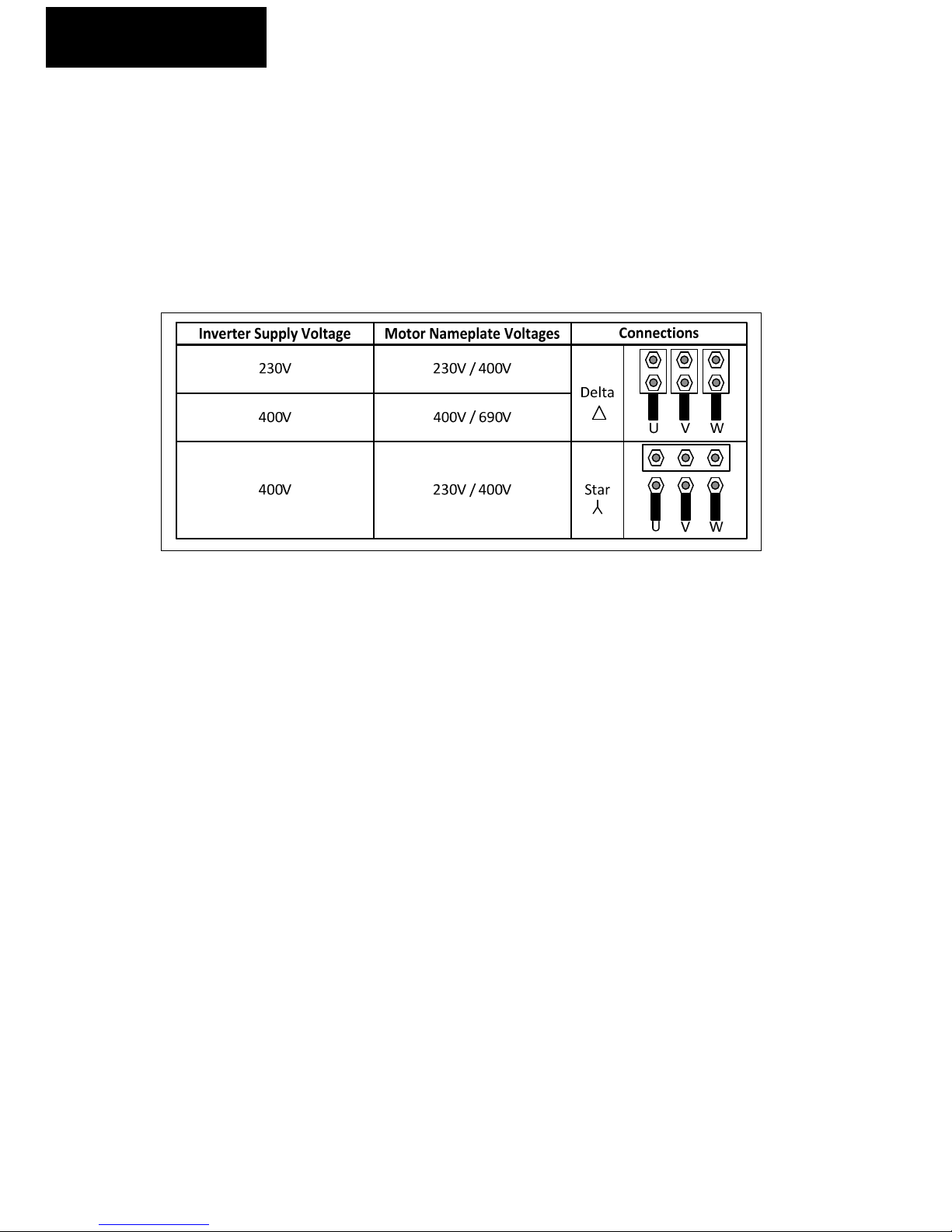
Motor connection
When connecting a 3 phase motor to an AC inverter drive, it is important that the motor terminal
box connections are correct for the supply voltage being used. Generally up to 3 W, the motor is
wound for 230V delta, 400V star. Generally above 3 W, the motor is wound for 400V delta, 690V
star.
Please check the motor nameplate for the correct connection.
The usual issues when the wrong connections are made:
230V AC drive connected to a 400V star connected motor or 400V AC drive connected to a 690V star
connected motor:
The motor will probably run if starting a lightly loaded motor. If the motor tries to start a heavy load
or if a heavy load is applied to the motor while running, the motor will stall due to a lac of torque
and the drive will trip on an over current or I x t trip.
400V AC drive connected to a 230V delta connected motor:
On enable, the drive will either trip on an over current trip or the drive will go into current limit and
trip on an “I x t trip”.
NOTE: Please ma e sure there are no phase to earth short circuits on the motor/motor cable before
powering up the HIB. A phase to earth short circuit at power up may cause drive failure on some
models of HIB.

HIB Enclosed Inverter User Guide
P a g e | 5
4
Operation
Operation
The HIB range of enclosed motor inverters is designed to be as close to a plug and play product as
possible. They require a suitable 3 phase and earth or single phase and earth power supply and a
three wire and earth motor cable. Please note it is best practice to use a screened motor cable.
The HIB is equipped with
•Green start button
•Red stop button
•Red keyed latching Inverter Disable button (Not Emergency Stop button)
•Drive healthy lamp
•Drive running lamp
•Forward/Reverse switch
•A single turn speed potentiometer
•An interlocked mains isolator is also provided; the enclosure door cannot be opened unless
the isolator is in the off position.
The HIB will provide a soft start and a soft stop along with motor thermal protection.
The key release disable button on this equipment IS NOT an Emergency Stop button It is an
inverter disable button This button provides a ‘Category zero stop’ (coast to stop) by disabling
the inverters output It is a low integrity level, PLa system and has no built in redundancy or
safety relay control This button should not be used as a means of isolation of the motor or
equipment for maintenance or any other function This button must not be used as an Emergency
Stop button Please check this type of system is adequate for your machine/equipment
Start Button - When pressed (providing the inverter disable button is not pressed) the inverter will
start and ramp up to the speed set by the speed potentiometer.
Stop Button - When pressed the inverter will ramp to a stop.
Inverter Disable Button - When pressed the inverter will disable its outputs immediately and the
connected motor will ‘coast to a stop’. This is a twist release button and can be locked in the “in”
position. This is not an Emergency Stop button and should not be used for safety isolation
Speed Potentiometer - When turned in the anti clockwise direction this will reduce inverter output
speed. When turned in the clockwise direction this will increase inverter output speed.
Forward/Reverse Switch - When set in the forward position the inverter will turn a motor in the
clockwise direction of rotation when looking at the motor shaft from in front of the motor (providing
U,V,W on the inverter are connected to U1, V1, W1 on the motor).
When set in the reverse position the inverter will turn a motor in the anti-clockwise direction of
rotation when looking at the motor shaft from in front of the motor (providing U,V,W on the inverter
are connected to U1, V1, W1 on the motor).

P a g e | 6
HIB Enclosed Inverter User Guide
4
Operation
Healthy Lamp - This lamp will be illuminated when the HIB inverter is in the healthy state (not
tripped).
Running Lamp - This lamp will be illuminated when the HIB inverter is running (inverter output
enabled).
Mains Isolator - With the mains isolator in the off position mains power will be removed from the
control box. Mains power will still be present at the input connections to the isolator only.
HIB Parameter Settings
The following parameters have been pre-programmed in to the HIB HD700 Inverter drive
Single Phase Input
Parameter
Setting
Description
P00.04
1
Terminal control mode
P00.05
3
Analogue input 1 reference
P00.14
2
Digital input selector
P00.17
0
Auto
-
Start after power off to disabled
P00.23
1
Extended parameter access
P
09.14
1
Digital input 3 invert
P12.09
0
Input phase loss trip disabled
Three Phase Input
Parameter
Setting
Description
P00.04
1
Terminal control mode
P00.05
3
Analogue input 1 reference
P00.14
2
Digital input selector
P00.17
0
Auto
-
Start after power off to disabled
P00.23
1
Extended parameter access
P09.14
1
Digital input 3 invert
NOTE Please make sure that the following parameters are set according to the motor nameplate
P00 01 – Motor rated voltage
P00 02 – Motor rated current
P00 03 – Motor rated frequency

HIB Enclosed Inverter Guide
P a g e | 7
5
Circuit Diagrams
Circuit Diagrams
230V Single phase input
With Optional EMC filter diagram shown
P a g e | 8
HIB Enclosed Inverter Guide
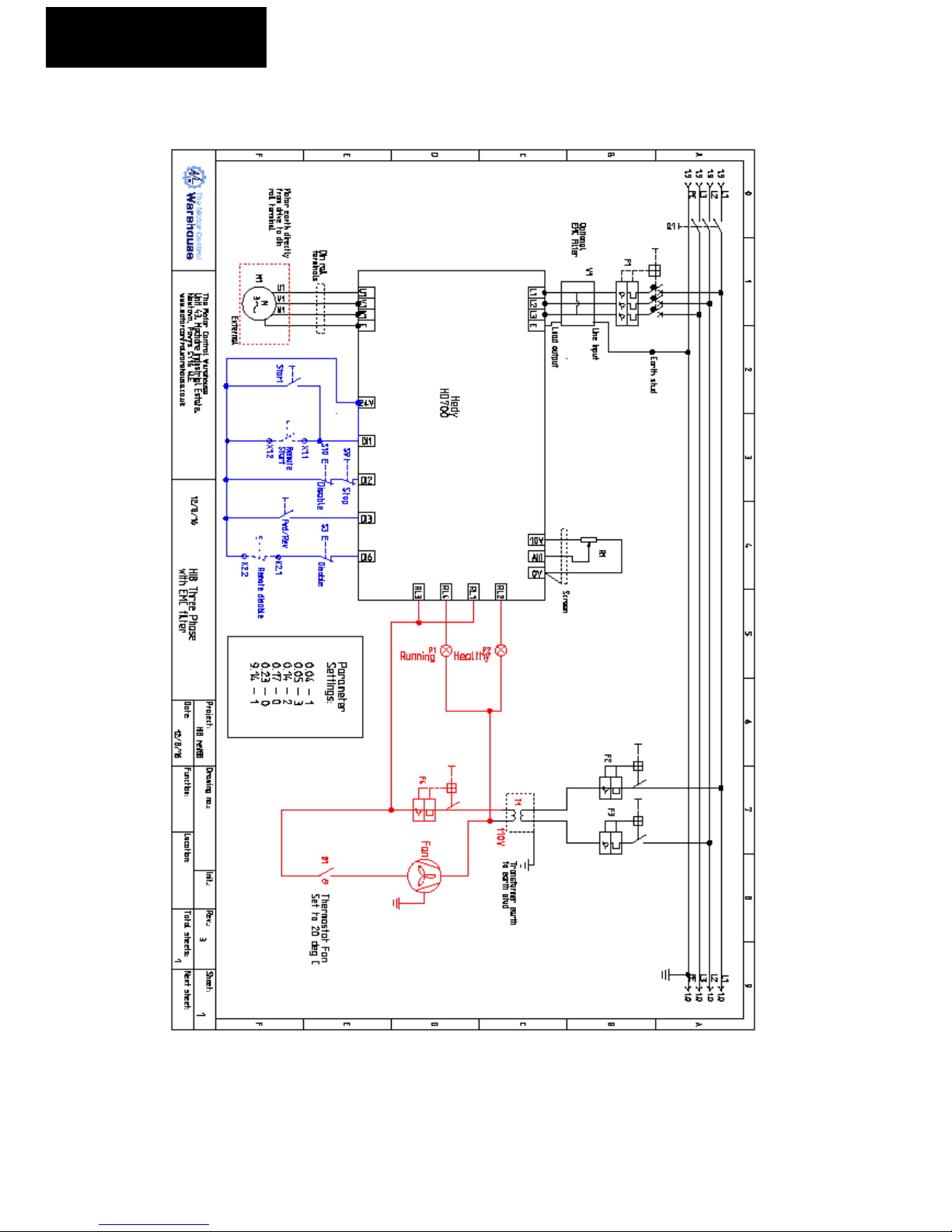
5
Circuit Diagrams
400V Three Phase Input
With Optional EMC filter diagram shown

Other Enclosed Products from Motor Control Warehouse
•Enclosed Star Delta Starters, three phase input from 7.5kW to 90kW. Trip Class 10
and Trip Class 20 ratings available.
•Enclosed Soft Starters, from 7.5kW to 55kW, three phase input. ll these products
are rated at trip class 10 (medium industrial loads).
Features
IP65 Powder coated steel enclosure
Interlocked mains isolator
10k MCBs – power and control
Tri-rated cable
Start/Stop pushbuttons
Motor outputs to terminals
Terminals for external start/stop
Key release E-Stop button
djustable changeover timer
110V C/230V C/400V C Control
voltage options
Features
IP65 Powder coated steel enclosure
10k MCBs – power and control
Interlocked mains isolator
Motor thermal overload relay
Internal bypass contactor
Stop/start pushbuttons
Keyed soft stop button
Running and healthy lamps
Customer terminals
24Vdc power supply
Tri-rated cable
Fairford Electronics DFE Soft Start
www.motorcontrolwarehouse.co.uk

HIB HEDY HD700 Easy Menu Parameters
Parameter Parameter name HIB
Settin Parameter Parameter name HIB
Settin
P00.01 Motor rated voltage 230V or
400V P00.13 V/f control mode 0
P00.02 Motor rated current By model P00.14 Digital input selector 2
P00.03 Motor rated frequency 50.00Hz P00.15 Relay 1 selector 0
P00.04 Control mode 1 P00.16 Preset speed 1 5.00Hz
P00.05 Reference source selector 3 P00.17 uto-Start fter Power
Off
0
P00.06 Minimum reference (speed) 0.00Hz P00.22 Password 0
P00.07 Maximum reference (speed) 50.00Hz P00.23 Extended group access 0
P00.08 cceleration time 10.00s P00.24 Load defaults 0
P00.09 Deceleration time 20.00s P09.14 DI 3 input invert 1
P00.10 Stop mode selector 0
P00.11 I 1 mode selector 6
P00.12 Low speed voltage boost level By model
HIB HEDY HD700 Control Terminal Connections
This manual suits for next models
14
Table of contents


