manuals.online logo
Brands
  1. Home
  2. •
  3. Brands
  4. •
  5. Kisae
  6. •
  7. Inverter
  8. •
  9. Kisae MW 1204 User manual

Kisae MW 1204 User manual

True Sinewave Power Inverter
SW1204 SW2405 SW1204i SW2405i
MW1204 MW1204i
Owner’s Manual
Picture shown SW1204i-EU
.
For safe and optimum performance, the Power Inverter must be used properly. Carefully read
and follow all instructions and guidelines in this manual and give special attention to the
CAUTION and WARNING statements.
PLEASE KEEP THIS MANUAL FOR FUTURE REFERENCE
Disclaimer
While every precaution has been taken to ensure the accuracy of the contents of this guide,
KISAE Technology assumes no responsibility for errors or omissions. Note as well that
specifications and product functionality may change without notice.
Important
Please be sure to read and save the entire manual before using your KISAE Power Inverter.
Misuse may result in damage to the unit and/or cause harm or serious injury. Read manual
in its entirety before using the unit and save manual for future reference.
Product Numbers
Modified Sinewave MW Series:
120V model
MW120412V 400W 120VAC Modified Sinewave Inverter (US - NEMA 5-15)
230V model
MW1204i-EU12V 400W 230VAC Modified Sinewave Inverter (Schuko - CEE 7/4)
MW1204i-UK12V 400W 230VAC Modified Sinewave Inverter (British - BS1363)
MW1204i-AU12V 400W 230VAC Modified Sinewave Inverter (Australia - NS/NZS 3112)
True Sinewave SW Series:
120V model
SW1204 12V 400W 120VAC True Sinewave Inverter (US - NEMA 5-15)
SW2405 24V 500W 120VAC True Sinewave Inverter (US - NEMA 5-15)
230V model
SW1204i-EU12V 400W 230VAC True Sinewave Inverter (Schuko - CEE 7/4)
SW1204i-UK12V 400W 230VAC True Sinewave Inverter (British - BS1363)
SW1204i-AU12V 400W 230VAC True Sinewave Inverter (Australia - NS/NZS 3112)
SW2405i-EU24V 500W 230VACTrue Sinewave Inverter (Schuko - CEE 7/4)
SW2405i-UK24V 500W 230VAC True Sinewave Inverter (British - BS1363)
SW2405i-AU24V 500W 230VAC True Sinewave Inverter (Australia - NS/NZS 3112)
Service Contact Information
Email: [email protected]
Phone: 1-877-897-5778
Web: www.kisaetechnology.com
1. INTRODUCTION
Thank you for purchasing the KISAE Power Inverter. With our state of the art, easy to use
design, this product will offer you reliable service for providing AC power for your home, cabin,
RV or Trailer. The KISAE Power Inverter can run many AC-powered appliances when you
need AC power anywhere.
This manual will explain how to use this unit safely and effectively. Please read and follow
these instructions and precautions carefully.
IMPORTANT SAFETY INFORMATION
This section contains important safety information for the KISAE Power Inverter. Each time,
before using the KISAE Power Inverter, READ ALL instructions and cautionary markings on or
provided with the inverter, and all appropriate sections of this guide.
The KISAE Power Inverter contains no user-serviceable parts. See Warranty section for how
to handle product issues.
WARNING: Fire and/or chemical burn hazard
• Do not cover or obstruct any air vent openings and/or install in a zero-clearance compartment.
WARNING: Failure to follow these instructions can result in death or series injury
• When working with electrical equipment or lead acid batteries, have someone nearby in case
of an emergency.
• Study and follow all the battery manufacturer’s specific precautions when installing, using
and servicing the battery connected to the inverter.
• Wear eye protection and gloves.
• Avoid touching your eyes while using this unit.
• Keep fresh water and soap on hand in the event battery acid comes in contact with eyes. If
this occurs, cleanse right away with soap and water for a minimum of 15 minutes and seek
medical attention.
• Batteries produce explosive gases. DO NOT smoke or have an open spark or fire near the
system.
• Keep unit away from moist or damp areas.
• Avoid dropping any metal tool or object on the battery. Doing so could create a spark or
short circuit which goes through the battery or another electrical tool that may create an
explosion.
WARNING: Shock Hazard. Keep away from children!
• Avoid moisture. Never expose unit to snow, water etc.
• Unit provides household AC, treat AC output sockets the same as regular wall AC sockets at
home.
WARNING: Explosion hazard!
• DO NOT use the KISAE Power Inverter in the vicinity of flammable fumes or gases (such as
propane tanks or large engines).
• AVOID covering the ventilation openings. Always operate unit in an open area.
LIMITATIONS ON USE
Do not use in connection with life support systems or other medical equipment or devices.
2. PRODUCT DESCRIPTION
The KISAE Power Inverter package includes the items list below.
• Power Inverter base unit
• Owner’s manual
• DC Input cable accessory
3. INSTALLATION
WARNING: KISAE Technology recommends that all wiring be done by a certified technician or
electrician to ensure adherence to the applicable electrical safety wiring regulations and
installation codes. Failure to follow these instructions can damage the unit and could also
result in personal injury or loss of life.
CAUTION: Before beginning your power inverter Installation, please consider the following:
• The Power Inverter base unit should be used or stored in an indoor area away from direct
sunlight, heat, moisture or conductive contaminants.
• When placing the unit, allow a minimum of three inches of space around the unit for optimal
ventilation.
Understanding the unit
features
Material Prepare for Installation
Typical Wiring block diagram of the Power Inverter:
Battery Bank:
• The use of deep cycle battery is highly recommended for power inverter application
• For battery size, you need to identify how long you wish to operate the load(s). KISAE does
recommend that you purchase as much battery capacity as possible. See more on
“Estimated Run time and Load” in Section 4.
• Please use 12V Battery Bank system for 12V DC Input Inverter (SW1204, MW1204,
SW1204i and MW1204i series). Use 24V Battery Bank system for 24V DC Input Inverter
(SW2405 and 2405i series). Using 12V DC Input Inverter on 24V Battery System will
damage the inverter and may caught fire.
Fuse or Circuit Breaker:
• DC-rated fuse or DC-rated circuit breaker connected along the DC positive line is required.
• Select a fuse or circuit breaker with 60A/16V minimum rating for the 12V DC Input Inverter(s)
and 35A/ 30V minimum rating for the 24V DC Input Inverter(s).
• Based on the size of the battery bank chosen on the 12V or 24V Battery Bank system above,
determine the overall short circuit current rating of the battery bank from the battery
manufacturer. The fuse or circuit breaker chosen has to be able to withstand the short circuit
current that may be generated by the battery bank.
Disconnect Switch:
• Select a Disconnect Switch with the same or higher rating of the selected fuse or circuit
breaker from the above.
• The Disconnect Switch is used to disconnect the DC power between the power inverter and
the battery bank during service, maintenance or trouble shooting.
DC Input Cable:
• Use of low resistance wire is required for all the DC connections between the inverter and
the battery bank.
• Uses minimum #8 AWG wire with maximum cable length of 5 feet for 12V DC Inverter
system and #10 AWG wire for 24V DC Inverter system.
Installing the Power Inverter System
WARNING: Electrical Shock Hazard
The unit ‘On/Off’ switch does not disconnect the DC power from the battery. Use the DC
Disconnect Switch or disconnect the DC input cables connection to disconnect the DC power
from the battery before working on any circuits connected to the unit. Failure to follow these
instructions can result in death or serious injury.
CAUTION: Unit Damage
Reversing the battery connection to the DC Input terminals will damage the unit and it cannot
be repaired. Damage caused by reverse polarity connection is not covered by the warranty.
Power Inverter Installation (All except MW series)
• Choose an appropriate mounting location.
• For indoor use, the orientation of the unit can be mounted in any direction except with the
DC Input panel facing upwards or downwards.
• Use mounting template below to mark the positions of the mounting screws. Drill the 4
mounting holes and place the inverter in position and fasten the inverter to the mounting
surface.
Power Inverter DC Input Connection:
• Connect one end of the negative DC input cable to the Power Inverter DC negative terminal
(black).
• Connect the other end of the negative DC input cable to the battery negative terminal.
• Make sure the Disconnect Switch is in the OFF position.
• Connect one end of the positive DC input cable to the Inverter DC positive terminal (red).
• Connect the other end of the positive DC input cable to one of the terminals of the
Disconnect Switch.
• Connect a DC input cable between the other terminal of the Disconnect Switch and one side
of the terminal of the fuse holder.
• Connect a DC input cable between the other terminal of the fuse holder and the battery
positive terminal.
• Install the selected fuse to the fuse holder.
• Turn Disconnect Switch to ON position.
Connect unit with provided accessories (Battery Clips or Lighter Plug Cable)
Using the Lighter Plug Cable: (SW1204 series and MW1204 series only)
CAUTION: Due to the limitations of the 12V lighter plug socket in vehicles, the unit should be
used with the DC cable with lighter plug only to supply AC power to products that require
150W (120VAC/1.3 A or 230V/0.65A) or less. If the appliance requires more than 150W, use
the DC Battery Cable Clips for battery connection.
• Attach the red ring-type connector to the positive (+) DC terminal (red) on the power
inverter and connect the black ring type connector to the negative (-) DC terminal (black)
on the Power inverter.
• Tighten the nut on each DC terminal.
• Insert the light plug of this cable to the fused 12V lighter plug socket.
• Unit is ready for use.
Using the Battery Clips Cable:
CAUTION: Please be sure all the connections are tight before the use of the unit.
• Attach the red ring-type connector to the positive (+) DC terminal (red) on the power
inverter and connect the black ring type connector to the negative (-) DC terminal (black)
on the Power inverter.
• Attach the negative (black) clip to the negative (-) battery terminal.
• Attach the positive (red) clip to the fuse or circuitry breaker of the 12V battery bank as
indicated on ‘Typical Wiring block diagram of the Power Inverter’ on page 5.
• Unit is ready for use.
Test the Power Inverter:
• Turn unit on by switching the On/Off button to ‘ON’ or ‘Power Save OFF’ position on the unit.
The ‘Power’ light turns on indicating the Power Inverter is ON. AC output is now available.
• Plug in a small AC load like a 40W table lamp or small appliance to the AC socket to verify
AC is available.
• The unit is successfully installed and functioning properly.
Test the GFCI Monthly (for unit come with GFCI socket only):
• Turn unit on and plug a small AC load (40W light bulb) to the GFCI socket.
• Check the AC Load is ON.
• Press the ‘TEST’ button on the GFCI socket, the socket will trip and the AC load turns OFF.
• Press the ‘RESET’ button to reset the GFCI and the AC Load will turns back ON.
• GFCI is functioning properly.
4. UNIT OPERATION
WARNING: RISK OF EQUIPMENT DAMAGE
• Do not connect an AC power source like utility power or generator to the AC outlets of the
inverter.
• For MW series, do not plug surge-protected power bars to the AC Output socket of the unit
Some surge protected components on the surge-protected power bar may not like the
modified sinewave output generate by the MW series inverter.
For SW Series with Power Save Mode:
Turn on the unit in ‘Power Save OFF’ mode
• Toggle the 3 position switch to ‘Power Save OFF’ position (bottom) to turn unit ON in
normal operation.
• Continuous AC Output is available at the AC output socket. Green ‘Power’ indicator will
turn ON and5V USB is available.
• Toggle the switch to middle position to turn unit off. ‘Power’ indicator will turn off.
Turn on the unit in ‘Power Save ON’ mode
• Toggle the 3 position switch to ‘Power Save ON’ position to turn unit ON with Power Save
feature. Green ‘Power’ indicator will turn ON, 5V USB is available.
• If no load or < 10W load is connected to the AC output of the unit, the RED ‘Fault’ LED will
flash, this indicates ‘Power Save’ mode is ON. The unit will provide few AC cycle for every
5 seconds.
• If >10W AC load is connected to the unit, the RED ‘Fault’ indicator will turn OFF indicating
that continuous AC output is provided.
Note: This special ‘Power Save’ mode is designed to let the unit run in standby mode and
check for any AC load with more than 10W every 5 seconds. If load connected is >10W, a
continuous AC Output is provided. The unit will automatically return to standby mode when
AC load connected drops to < 5W.
For MW Series or SW series without Power Save Mode:
Turn ON and OFF the unit
•Toggle the On/Off switch to ‘ON’ position to turn unit ON.
•‘Power’ indicator will turn ON indicates AC Output power is available.
•Toggle the On/Off switch to ‘Off’ position to turn unit off. ‘Power’ indicator will turn off.
Understanding the LED indicators
‘Power’ Indicator: Illuminated indicates unit is ON.
‘Fault’ indicator:
Illuminated continuously indicates fault was detected. Unit has shutdown. To reset unit,
remove the fault condition and reset unit by using the toggle switch and turn unit off and on
again.
For SW series with ‘Power Save Mode’ function, ‘Fault’ indicator flashing indicates ‘Power
Save’ mode is ON and power consumption on AC load is <10W.
Understanding the Fan Operation
The fan on the unit is load activated. It will automatically turn on when AC output power exceed
the pre-set values (~ 200W).
AC Load on Power Inverter
Although the Power Inverter can provide high surge power up to two times the rated output
power, some appliances may still trigger on the inverter protection system during start up or
surge period. A higher power inverter is required for those appliances.
Important: For Modified Sinewave Inverter MW series, some appliances like speed controllers
found in some fans, power tools and some power tools’ AC charger may not like the modified
sine wave generate by the inverter, those appliances may not work or may be damaged if they
are connected to the inverter. If you are unsure about powering any device with the inverter,
contact the manufacturer of the device.
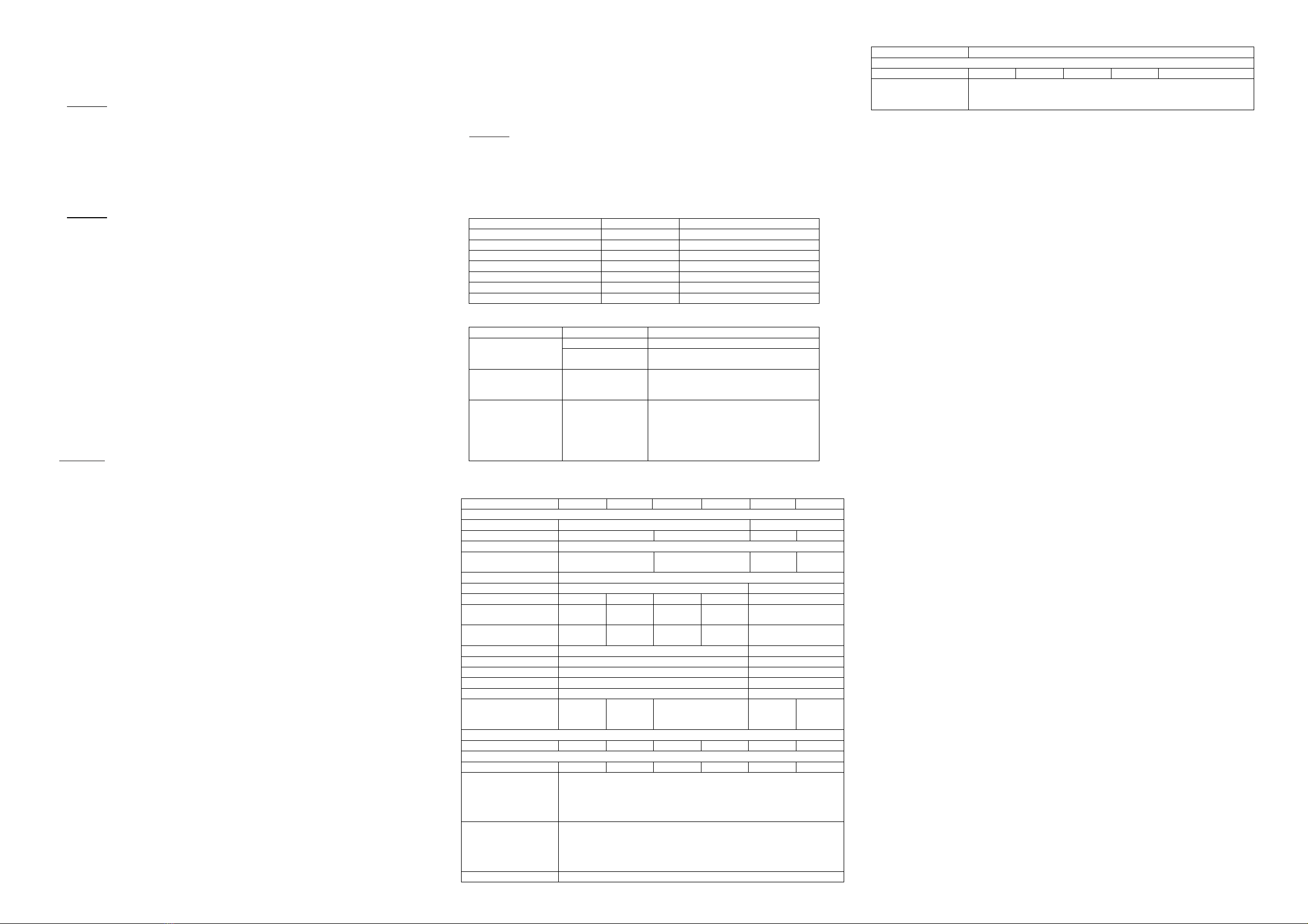
Estimated Run time on Load
Following run time is an estimate based on using a 12V-120AH battery bank for 12V system
and 24V-60AH battery bank 24V system. Actual runtime may vary.
Load Consumption Estimate Run time
Cordless Phone 5W 150 hrs
Clock / Radio 8W 100 hrs
Table Lamp 40W / 60W 27 hrs/ 18 hrs
Small Freezer (8.8 cu. ft.) 80W 15 hrs
20” LCD TV 100W 11.5 hrs
Flooded Light 500W 1 hr
Sump Pump (1/2 hp) 350W Not applicable (surge too high)
5. TROUBLESHOOTING
Problem Symptom Solution
The unit is off Turn unit ON using the toggle switchNo AC output and
‘Power’ LED is OFF No power to
inverter Check fuse or the Disconnect switch (if
installed) is either blown or turned OFF
No AC output. ‘Fault’
indicator is ON Unit has detected
fault and has
shutdown
Verify the fault condition (the load
connected may be too high). Make
correction and reset unit.
‘Fault’ indicator is
Flashing. AC Load
connected is turning
ON and OFF (For
unit with “Power
Save’ Feature only
‘Power Save’
mode is in use and
the AC load
connected is
<10W
Unit is normal.
Power consumption on AC load
connected is <10W, switch unit to
‘Power Save OFF’ mode to have a
continuous output or increase the AC
load to >10W.
6. SPECIFICATIONS
Note: Specifications are subject to change without notices.
Specifications MW1204 SW1204 MW1204i SW1204i SW2405 SW2405i
Inverter
AC Output Power 400 Watt 500 Watt
AC Output Current 3.33A 1.74A 4.17A 2.17A
AC Surge Power 800 Watt
AC Output Voltage 120Vac
60Hz 230Vac
50Hz 120Vac
60Hz 230Vac
50Hz
AC Output Waveform True Sinewave (<3% THD)
DC Input Voltage 12.5 VDC 25.0 VDC
No Load Current <0.3A N/A <0.3A N/A N/A
No Load Current
(Power Save OFF) N/A < 0.8 A N/A < 0.8 A <0.5 A
No Load Current
(Power Save ON) N/A < 0.1 A N/A < 0.1A <0.1 A
DC Operating Range 10.5 – 15.75VDC 21.0 – 31.0 VDC
Under Voltage Alarm 11.0 VDC 22.4 VDC
UV Shutdown 10.5 VDC 21.0 VDC
UV Recovery 12.0 VDC 23.6 VDC
OV Shutdown 15.75 VDC 31.0 VDC
AC Output Socket NEMA
5-15
NEMA
5-15
(GFCI) EU, AU, UK NEMA
5-15
(GFCI)
EU,
AU,
UK
DC Output
USB Output (5V) N/A 2.1A N/A 2.1A 2.1A 2.1A
Safety and Environmental
Agency Markings cETLus * cETLus * N/A CE cETLus * CE
Operating Temp. 0Ԩto 40Ԩ(32Ԭto 104Ԭ)
Storage Temp. -20Ԩto 60Ԩ(-4Ԭto 140Ԭ)
Relative Humidity 5 - 90% noncondensing
Operating Altitude Up to 6,560ft (2000 m) above sea level
Weights and Dimensions
Weights 0.73 kg 1.73 kg 0.80 kg 1.73 kg 1.73 kg
Dimensions
(LxWxH)
MW1204: 152 x 101 x 51 mm,
MW1204i: 158 x 105 x 67 mm
SW Series: 312 x 175 x 87mm
* The product is conforms to UL STD.458 and certified to CSA STD. C22.2 No.107.1
7. WARRANTY
One Year Limited Warranty
The limited warranty program is the only one that applies to this unit, and it sets forth all the
responsibilities of KISAE. There is no other warranty, other than those described herein. Any
implied warranty of merchantability of fitness for a particular purpose on this unit is limited in
duration to the duration of this warranty.
This unit is warranted, to the original purchaser only, to be free of defects in materials and
workmanship for one year from the date of purchase without additional charge. The warranty
does not extend to subsequent purchasers or users.
Manufacturer will not be responsible for any amount of damage in excess of the retail
purchase price of the unit under any circumstances. Incidental and consequential damages are
specifically excluded from coverage under this warranty.
This unit is not intended for commercial use. This warranty does not apply to damage to units
from misuse or incorrect installation/connection. Misuse includes wiring or connecting to
improper polarity power sources.
Return/Repair Policy:
If you are experiencing any problems with your unit, please contact our customer service
department [email protected] or Phone 1-877-897-5778 before returning product to
retail store. After speaking to a customer service representative, if products are deemed non-
working or malfunctioning, the product may be returned to the purchasing store within 30 days
of original purchase. Any defective unit that is returned to manufacturer within 30 days of the
date of purchase will be replaced free of charge. If such a unit is returned more than 30 days
but less than one year from the purchase date, manufacturer will repair the unit or, at its option,
replace it, free of charge. If the unit is repaired, new or reconditioned replacement parts may
be used, at manufacturer’s option. A unit may be replaced with a new or reconditioned unit of
the same or comparable design. The repaired or replaced unit will then be warranted under
these terms for the remainder of the warranty period. The customer is responsible for the
shipping charges on all returned items.
Limitations:
This warranty does not cover accessories, such as adapters and batteries, damage or defects
result from normal wear and tear (including chips, scratches, abrasions, discoloration or fading
due to usage or exposure to sunlight), accidents, damage during shipping to our service facility,
alterations, unauthorized use or repair, neglect, misuse, abuse, failure to follow instructions for
care and maintenance, fire and flood.
If your problem is not covered by his warranty, call our Customer Service Department
[email protected] or 1-877-897-5778 for general information if applicable.

Other manuals for MW 1204

2

This manual suits for next models

5

Other Kisae Inverter manuals

Kisae 120V Series User manual

Kisae

Kisae 120V Series User manual

Kisae 120V Series User manual

Kisae

Kisae 120V Series User manual

Kisae 3000W - 120V User manual

Kisae

Kisae 3000W - 120V User manual

Kisae SW1206 User manual

Kisae

Kisae SW1206 User manual

Kisae SW2420 User manual

Kisae

Kisae SW2420 User manual

Kisae 120V Series User manual

Kisae

Kisae 120V Series User manual

Kisae IC1220100 User manual

Kisae

Kisae IC1220100 User manual

Kisae SWXFR1210 User manual

Kisae

Kisae SWXFR1210 User manual

Kisae MW 1204 User manual

Kisae

Kisae MW 1204 User manual

Kisae 120V Series User manual

Kisae

Kisae 120V Series User manual

Kisae SWXFR1210 User manual

Kisae

Kisae SWXFR1210 User manual

Kisae SW 1220 User manual

Kisae

Kisae SW 1220 User manual

Kisae MW 1204 User manual

Kisae

Kisae MW 1204 User manual

Popular Inverter manuals by other brands

Northern Lights PX-300K1 Series A.C. Generator Operator's & parts manual

Northern Lights

Northern Lights PX-300K1 Series A.C. Generator Operator's & parts manual

Voltronic Power 1KVA quick guide

Voltronic Power

Voltronic Power 1KVA quick guide

Deger Energie DEGERtraker 3000NT Assembly instruction

Deger Energie

Deger Energie DEGERtraker 3000NT Assembly instruction

Northern Lights O843K Operator's manual

Northern Lights

Northern Lights O843K Operator's manual

Generac Power Systems Guardian 004373-3 owner's manual

Generac Power Systems

Generac Power Systems Guardian 004373-3 owner's manual

YASKAWA Solectria PVI 25TL-480-R Installation and operation guide

YASKAWA

YASKAWA Solectria PVI 25TL-480-R Installation and operation guide

Mitsubishi Electric fr-e700 series instruction manual

Mitsubishi Electric

Mitsubishi Electric fr-e700 series instruction manual

Genquip Gi1000 owner's manual

Genquip

Genquip Gi1000 owner's manual

GUANGDONG EAST POWER EA-IVS6000 Series user manual

GUANGDONG EAST POWER

GUANGDONG EAST POWER EA-IVS6000 Series user manual

Dometic TEC60 installation manual

Dometic

Dometic TEC60 installation manual

Omron 3G3MX2-AB001-V1 instruction manual

Omron

Omron 3G3MX2-AB001-V1 instruction manual

GRIDFREE TINY HOUSE installation manual

GRIDFREE

GRIDFREE TINY HOUSE installation manual

Scaled Instruments Davis Pro2 Replacement guide

Scaled Instruments

Scaled Instruments Davis Pro2 Replacement guide

kWiet Power DGK25E owner's manual

kWiet Power

kWiet Power DGK25E owner's manual

ICT 1500W Sine Wave Series instruction manual

ICT

ICT 1500W Sine Wave Series instruction manual

SunSynk SUN-8K-SG04LP3 user manual

SunSynk

SunSynk SUN-8K-SG04LP3 user manual

Deye SUN-1.5K-G user manual

Deye

Deye SUN-1.5K-G user manual

Dometic TEC 40D Operation operating manual

Dometic

Dometic TEC 40D Operation operating manual

manuals.online logo
manuals.online logoBrands
  • About & Mission
  • Contact us
  • Privacy Policy
  • Terms and Conditions

Copyright 2025 Manuals.Online. All Rights Reserved.