Soltaro QENDERCORE User manual

WWW.SOLTARO.COM –[email protected] –TEL 1300 376 582
Main Office & Showroom –8 Mohr Street, Tullamarine, VIC 3043
Registered Address –Level 9, 440 Collins Street, Melbourne VIC 3000 –ABN 78 800 728 807

2
User manual
D
WWW.SOLTARO.COM –[email protected] –TEL 1300 376 582
Main Office & Showroom –8 Mohr Street, Tullamarine, VIC 3043
Registered Address –Level 9, 440 Collins Street, Melbourne VIC 3000 –ABN 78 800 728 807
Table of Contents
Table of Figures 3
Qendercore Account Setup Instructions 4
Qendercore Hub Overview 6
Installation of Qendercore Hub 7
Connecting to Qendercore Hub 8
LOCAL ACCESS POINT (AP) 8
LOCAL NETWORK 10
Internet Connection 11
WiFi Network Setup –Manual Entry 11
WiFi Setup –WPS 12
Ethernet Connection Setup 13
Linking a Qendercore Account 15
Soltaro Inverter Setup 16
SOLTARO MAINTENANCE INDEX 17
INVERTER MEASUREMENTS 17
BASIC SETTINGS 18
ADVANCED SETTINGS 19
BMS REGISTERS 19
INVERTER OPERATIONS 20
INVERTER FAULTS 20
LED Status 21
Troubleshooting 22

3
User manual
Figure 1 –Account Login Screenshot 4
Figure 2 - Register Account Screenshot 5
Figure 3 - Qendercore Hub 6
Figure 4 - Qendercore Hub (Side View) 7
Figure 5 - WiFi AP 8
Figure 6 - Network Configuration 9
Figure 7 - Angry IP Scanner for Windows 10
Figure 8 - WiFiMan for Android 10
Figure 9 - Ethernet Network Configuration, Completed 10
Figure 10- Network Configuration, Completed 11
Figure 11 - Qendercore Hub (Side View) 12
Figure 12 - RJ45 Ethernet Pinout 13
Figure 13 - Qendercore Hub 14
Figure 14 - Qendercore Account, Unlinked 15
Figure 15 - Qendercore Account, Linked 15
Figure 16 - Setup Complete 16
Figure 17 - Network Configuration 16
Figure 18- Maintenance Authentication 16
Figure 19 - Soltaro Maintenance Index 17
Figure 20 - Inverter Measurements 17
Figure 21 - Basic Settings 18
Figure 22 - Setting Confirmation 18
Figure 23 - Setting Confirmation 18
Figure 24 - Advanced Settings 19
Figure 25 - BMS Registers 19
Figure 26 - Inverter Operations 20
Figure 27 - Inverter Faults 20
Figure 28 - Qendercore Hub LED's 21
WWW.SOLTARO.COM –[email protected] –TEL 1300 376 582
Main Office & Showroom –8 Mohr Street, Tullamarine, VIC 3043
Registered Address –Level 9, 440 Collins Street, Melbourne VIC 3000 –ABN 78 800 728 807
Table of Figures

4
User manual
Qendercore Account Setup Instructions
Before attempting setup, navigate to the Qendercore web portal at
https://www.qendercore.com/ and register a Qendercore end user account.
These account details will need to be entered to setup monitoring for your
Soltaro All in One 2. Click on “Create an Account”.
Figure 1 –Account Login Screenshot

5
User manual
Enter the email address for the end user, then click “Register”. An email will be sent
to this email address with instructions on how to complete setup of the account.
Figure 2 - Register Account Screenshot
6
User manual
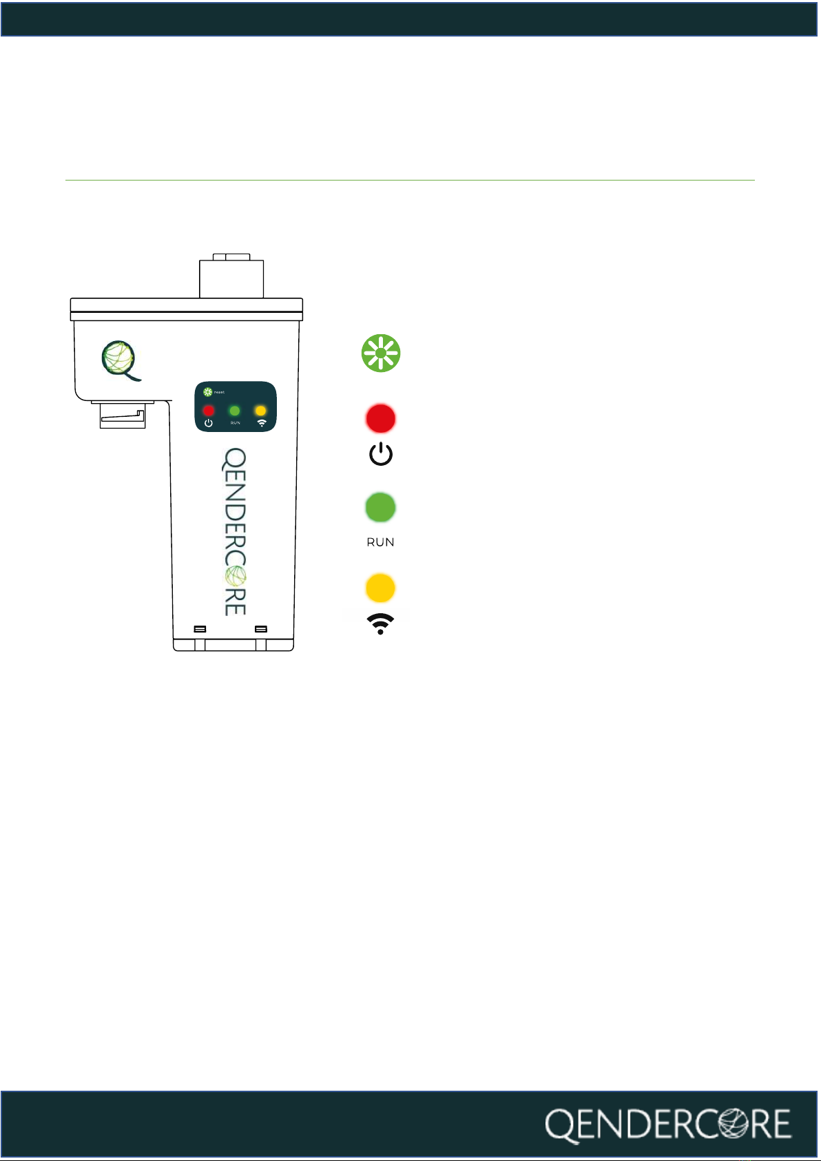
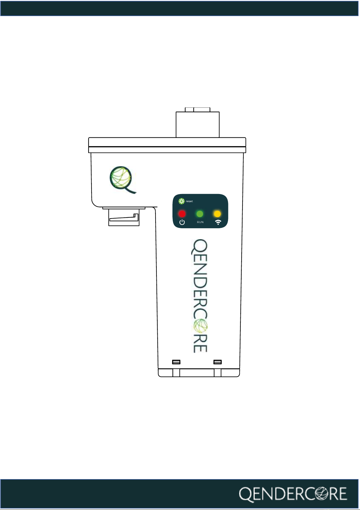
Figure 3 - Qendercore Hub
Qendercore Hub Overview
Interactive Button: Used to
change Hub State
Power LED: Used to indicate
Hub On/Off
Mode LED: Used to indicate
Hub Mode
Connectivity LED: Used to
indicate Hub Connectivity State

7
User manual
Installation of Qendercore Hub
Connect the Qendercore hub to your Soltaro All in One 2 by aligning the round
connector with the “EMS” connector on the inverter and pushing it upwards (DO
NOT CONNECT WHILE INVERTER IS ENERGIZED). Once connected, tighten the
outer lockring until it is firm. Once complete, switch on the inverter and wait for
the status LEDs (Green and Yellow) to start flashing.
Figure 4 - Qendercore Hub (Side View)
8
User manual
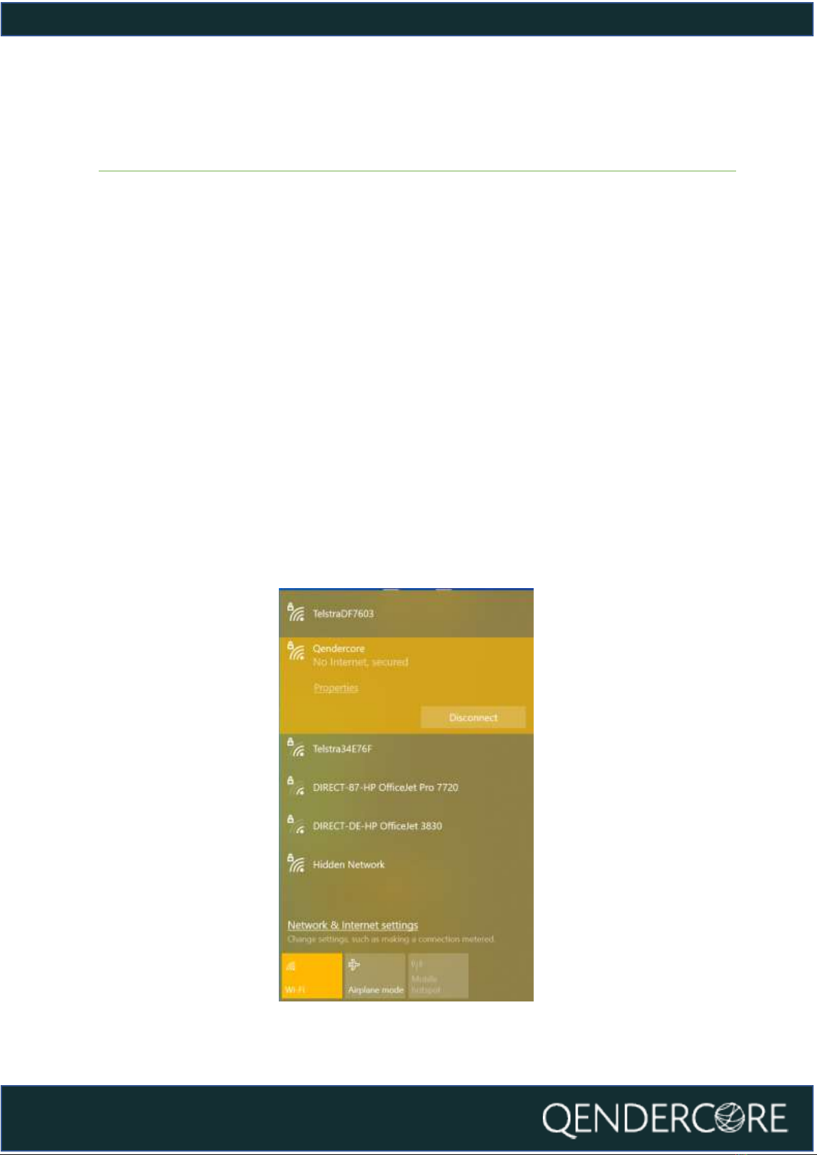
Figure 5 - WiFi AP
Connecting to Qendercore Hub
LOCAL ACCESS POINT (AP)
Once your Qendercore Hub is plugged in and inverter is powered, the “Power” LED
(RED) should light up. Shortly after, the Status lights will start flashing, push the
Interactive Button twice (two short presses) to enter Setup Mode. The “Mode” light
(Green) should start flashing on and off approximately every 1.5 seconds. Once in
Setup Mode you will need to push the Interactive Button three times (three short
presses) to enter Local AP Mode. The “Mode” light (Green) should now be flashing
on and off every 0.1 seconds.
Once in Local AP mode, the Qendercore Hub will provide a temporary WiFi access
point that can be connected to by one device (eg. computer, smartphone, or
tablet) to complete the setup process. Using your device, open your WiFi settings,
and connect to the AP named “Qendercore”. The password is “p1234567”. (NOTE:
On some smart devices, it may be necessary to activate Airplane Mode before
switching WiFi back on, to prevent the device from prioritizing mobile data
connections) It is normal for this network to show a “No Internet” message from
your device.

9
User manual
Once connected to the Local AP of the Hub, navigate to your preferred Web
Browser, and input the Address:
http://qendercore.local/ (Only available for Windows 10 + Above)
OR
192.168.89.89
You will be directed to the page below.
From here, you can navigate to Internet Connection or Soltaro Inverter Setup
Figure 6 - Network Configuration

10
User manual
LOCAL NETWORK
Press the Interactive Button twice (Two short presses) to activate Setup Mode on
the Qendercore Hub. The “Mode” light (Green) should start flashing on and off
approximately every 1.5 seconds. Connect your smart device or computer to the
same network as the Qendercore Hub. On computers with Windows 10 or above,
navigate to http://qendercore.local/ in your chosen web browser. This should
automatically navigate to the Qendercore Setup Page. Otherwise, login to the
Modem or use a method of IP scanning to determine the assigned IP address for
the Qendercore Hub (Screenshots below from Angry IP Scanner for Windows and
WiFiMan for Android).
Figure 7 - Angry IP Scanner for Windows
Figure 8 - WiFiMan for Android
Navigate to the correct IP address (Or http://qendercore.local/ while the Hub is in
Setup Mode. You will be directed to the below webpage, on this webpage you can
elect to set a WiFi network as a backup option WiFi Network Setup –), or you can
continue to link a Qendercore Account (Linking a Qendercore Account).
Figure 9 - Ethernet Network Configuration, Completed
11
User manual
Internet Connection
There are various methods of connecting your Qendercore hub to your local
network:
1. Local Access Point –WiFi (LOCAL ACCESS POINT (AP))
2. Wi-Fi Protected Setup (WPS) –WiFi (Only available for Wi-Fi routers with
WPS Push Button/ PBC functionality) (WiFi Setup –WPS)
3. Ethernet Connection (Error! Reference source not found.)
These methods are outlined in the following sections.
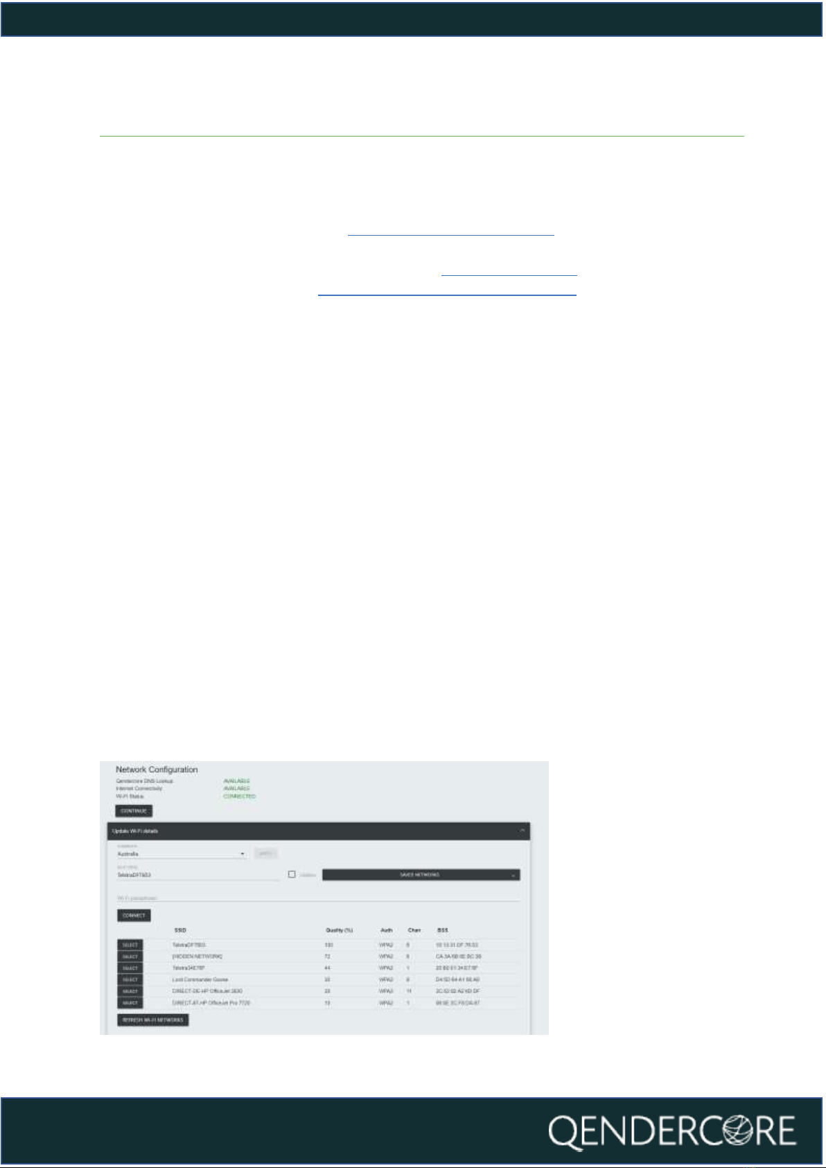
WiFi Network Setup –Manual Entry
Once you have connected to your Qendercore Hub following the steps above,
input your installation Country and press “Apply”. Select your preferred Wi-Fi
network by clicking on it and input the correct password for this network into the
“Wi-Fi Passphrase” section. If your chosen network is not broadcasting an SSID,
you can select “Hidden Network” to enter an SSID manually (please ensure that
“Hidden” is selected in this scenario). Once all details have been input, please press
CONNECT to attempt Wi-Fi connection to the chosen Wi-Fi network.
Once it has successfully connected to the Local network, the page will refresh and
will show you the availability of:
1. Qendercore DNS Lookup
2. Internet Connectivity
3. Local Wi-Fi connection
If any of these are not showing as “Connected” or “Available”, please refer to the
Troubleshooting section of the manual.
If everything is OK, please press the “Continue” button to move to Linking a
Qendercore Account.
Figure 10- Network Configuration, Completed

12
User manual
Figure 11 - Qendercore Hub (Side View)
WiFi Setup –WPS
Once your Qendercore Hub is plugged in and the Status lights are flashing, push
the Interactive Button twice (two short presses) to enter Setup Mode. The “Mode”
light (Green) should start flashing on and off approximately every 1.5 seconds.
Once in Setup Mode you will need to push the Interactive Button once (one long
press 3-6 seconds) to enter WPS Pairing Mode. The “Mode” light (Green) should
now be flashing on and off every 0.4 seconds.
Once in WPS mode, follow the instructions for the target WiFi router to activate
WPS Pairing mode on the router. This could be by pushing a button on the router,
or it may require logging into the router’s configuration wizard. Please confirm the
process with the router manufacturer if required.
Once both devices are in WPS Pairing Mode at the same time, the Hub should
automatically connect to the target WiFi router. Once pairing is complete and
WiFi network connection is confirmed, the “Connectivity” (Yellow) LED will flash
faster in accordance with the LED Status section of this document. Once the LED
remains on, and blinks off every 3 seconds, communications have been
established with the Qendercore servers, and it is ready for account setup (Linking
a Qendercore Account).
13
User manual
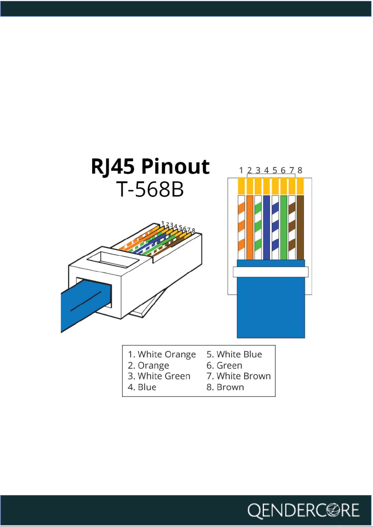
Ethernet Connection Setup
Assemble the Ethernet connector by passing the Ethernet cable through the
weatherproof gland, and then fitting off an RJ45 connector using the T-568B
connection standard. Once the Status LEDs of the Hub are flashing, connect the
RJ45 connector to the Ethernet port of the Qendercore Hub and twist the
weatherproof lockring onto the Ethernet port. Tighten the weatherproof gland
until it is firm.
Figure 12 - RJ45 Ethernet Pinout
14
User manual
Figure 13 - Qendercore Hub
Once network connection is detected via the Ethernet cable, the “Connectivity”
(Yellow) LED will flash faster in accordance with the LED Status section of this
document. Once the LED remains on, and blinks off every 3 seconds,
communications have been established with the Qendercore servers, and it is
ready for linking a Qendercore account (See “Link a Qendercore Account”).
15
User manual
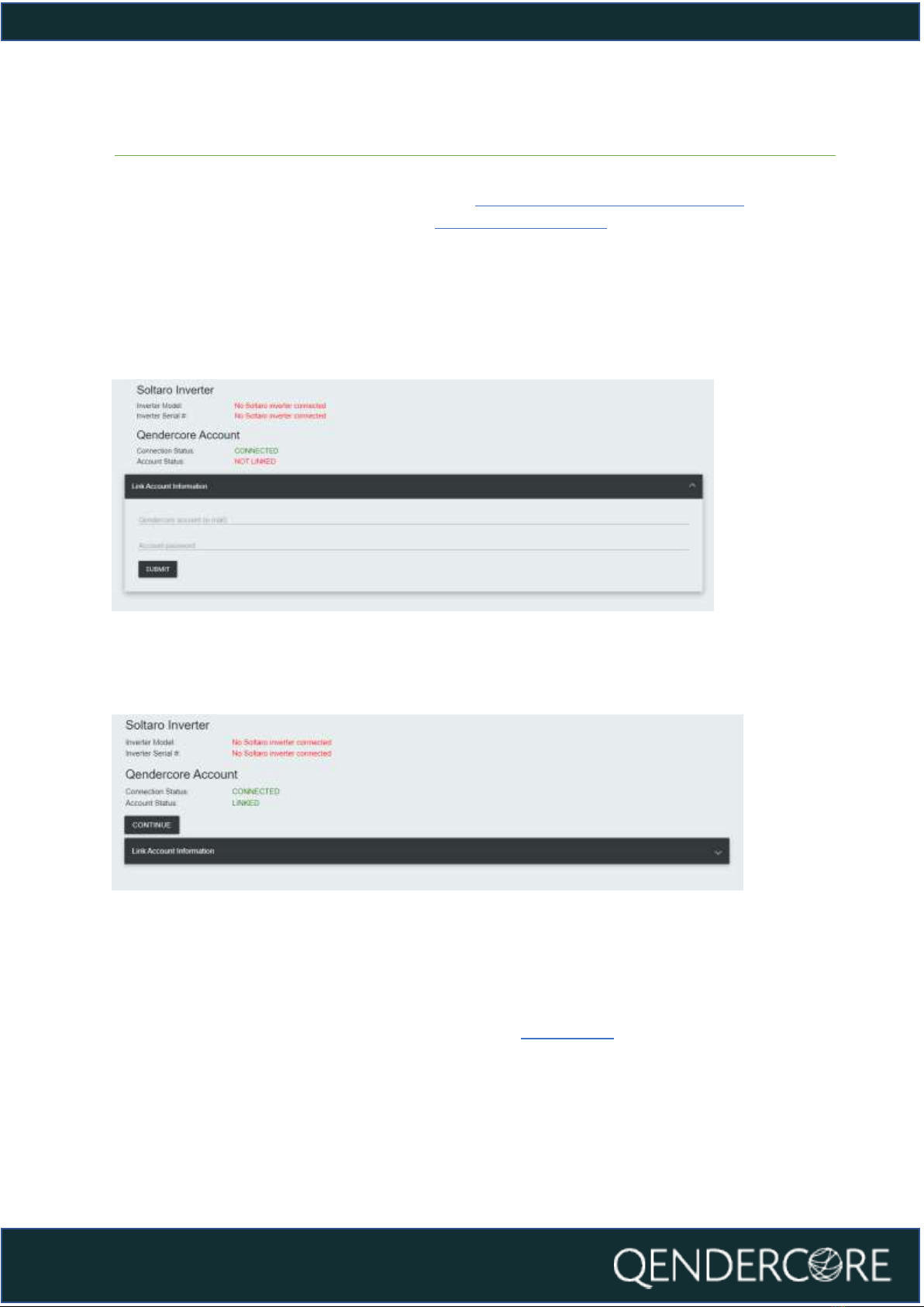
Linking a Qendercore Account
After connecting to your Qendercore Hub (Connecting to Qendercore Hub)and
configuring your internet connection (Internet Connection), click on “Continue” to
be taken to Qendercore Account Linkage. The Inverter Model and Serial # will be
shown at the top and the Qendercore Connection Status will be shown
underneath. Please input the Account information for the End User associated
with this Inverter Serial #, and then press Submit. The Hub will attempt to connect
to the Qendercore servers and verify the information, if correct, this Hub will be
automatically linked to the End User’s account.
Figure 14 - Qendercore Account, Unlinked
Once initial verification has been completed, the Account Status should display
“Linked”. Please press “Continue”.
Figure 15 - Qendercore Account, Linked
After pressing “Continue”, you will be directed to the page below. Setup Mode will
end, and the Qendercore Hub Setup is complete. You will be able to view your
connected inverter on your Qendercore Account (Please allow up to 30 minutes
for information to populate for the first time). LEDs should change status to
indicate setup mode exited and account linked (LED Status
Error! Reference source not found.Error! Reference source not found.)

16
User manual
Figure 16 - Setup Complete
Soltaro Inverter Setup
After connecting to your Qendercore Hub (Connecting to Qendercore Hub), click
on the button in the top right corner to be taken to the Soltaro Maintenance
Index. The button can be used on all pages except the Soltaro Maintenance
Index page to reach the Soltaro Maintenance Index.
Figure 17 - Network Configuration
You will be prompted to sign in. Leave the Username blank, and input “1111” into
the Password section, then press “Sign In”.
Figure 18- Maintenance Authentication
17
User manual
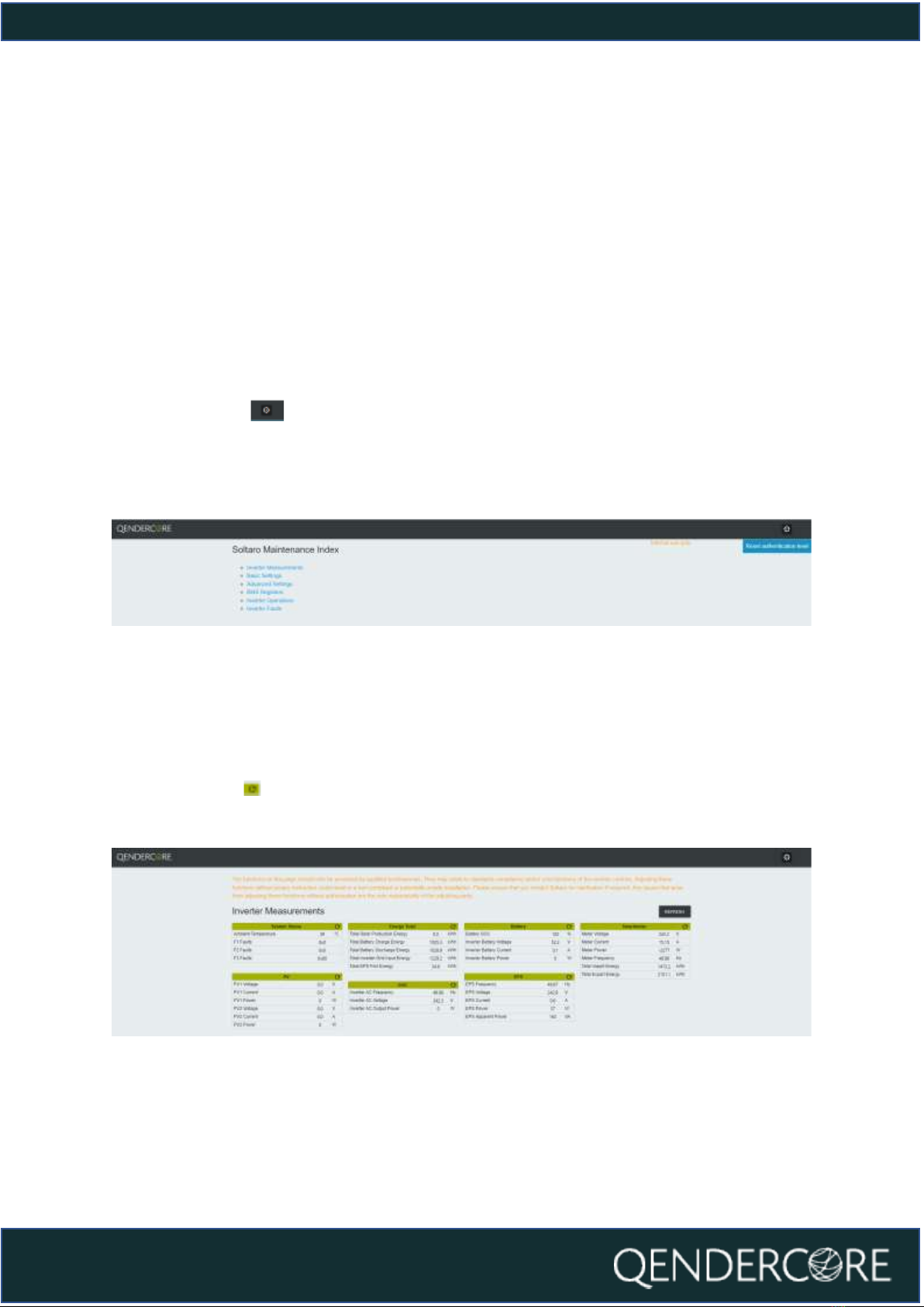
SOLTARO MAINTENANCE INDEX
Once you have signed in, you will be at the Soltaro Maintenance Index. From here,
you can access:
●Inverter Measurements
●Basic Settings
●Advanced Settings
●BMS Registers
●Inverter Operations
●Inverter Faults
You can use the button in the top right corner to log out and reset your
authentication if required. Click on any of the options to be directed to the relevant
section.
Figure 19 - Soltaro Maintenance Index
INVERTER MEASUREMENTS
This page will show you the values being read by the connected inverter. The
values can be updated as required using the “Refresh” button in the top right, or
by pushing the button for each individual group.
Figure 20 - Inverter Measurements
18
User manual
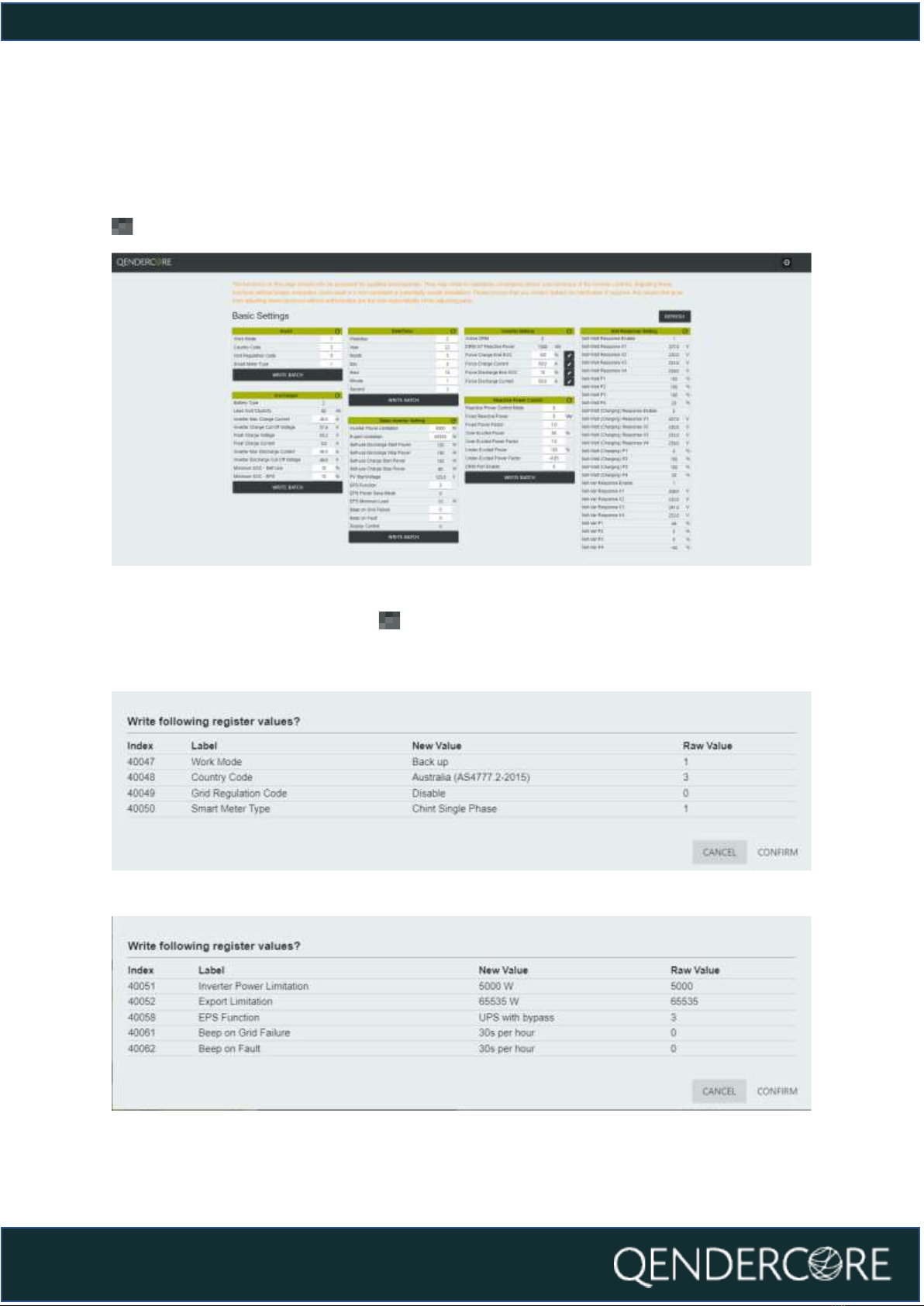
BASIC SETTINGS
The Basic Settings page is for inverter settings related to typical installations.
Sections with “Write Batch” at the bottom must be updated in batches. Fields with
next to them must be updated one by one.
Figure 21 - Basic Settings
Once you click “Write Batch” or , you will be given a confirmation popup with
the values you are about to change. Check that they are correct, and then click
“Confirm”. A description of the new value is provided where it is relevant.
Figure 22 - Setting Confirmation
Figure 23 - Setting Confirmation

19
User manual
ADVANCED SETTINGS
The Advanced Settings page is provided for settings not typically required for most
installations, and to provide a verification page for compliance-related settings.
Figure 24 - Advanced Settings
BMS REGISTERS
The BMS Registers page is provided to show values recorded by a connected
Soltaro Battery.
Figure 25 - BMS Registers

20
User manual
INVERTER OPERATIONS
The Inverter Operations page provides the following functionality:
-Inverter Clock Synchronization
oInverter Clock can be synchronized to the Browser (Your Device) or
Hub (Qendercore Hub) time. Please note, Hub Synchronization is only
available if Qendercore Hub has a valid internet connection to
validate the correct time via our servers. Both options are intended to
update the inverter clock, so it is only necessary to use one option.
-Restore Factory Defaults
-Emergency Charge
oTriggers a 10A, 52V voltage output on the inverter, without requiring
battery communications. Intended to “wake up” batteries that have
been dormant at low SOC where required.
-Storm Charge
oTriggers the inverter to charge any connected batteries to the
ChargeEndSOC% at the maximum allowable current. Recommended
to set ChargeEndSOC% to 100% when using this functionality.
Figure 26 - Inverter Operations
INVERTER FAULTS
This page will show you the last 10 fault codes recorded by the inverter locally. An
explanation of the recorded fault codes is provided at the bottom of the page for
your convenience. The Numbers in the second table correlate to the Fault Number
in the first table. Date/Time of each fault is based on the Inverter Clock at the time
that the fault occurred.
Figure 27 - Inverter Faults
Table of contents
Other Soltaro Inverter manuals

Soltaro
Soltaro AIO2-INS Series User manual

Soltaro
Soltaro SOLTARO-10K User manual

Soltaro
Soltaro AIO2 Owner's manual

Soltaro
Soltaro AIO2-BTLV Series User manual

Soltaro
Soltaro All-In-One ESS User manual

Soltaro
Soltaro AIO2-INS Series User manual

Soltaro
Soltaro Life04 Series User manual

Soltaro
Soltaro Hyper Series User manual


