MDM MDM-1 FOX Technical specifications

Zakład Remontów i Produkcji Sprzętu Lotniczego
Edward Margański
Bielsko - Biała, POLAND
F L I G H T M A N U A L
o f
MDM-1 „FOX“ G L I D E R
Issue III, October 1996
Factory No
Registration marking
Pages identified by "Appr." are approved by airworthiness Authority
(Civil Aircraft Inspection Board, POLAND).
Original date of approval:
This glider is to be operated in compliance with information and limitations contained in this Manual.
Translated by :
.....................
Tadeusz Zboś, MSc. Eng.

MDM-1 „FOX” FLIGHT MANUAL
0.1
Issue III
0. ISSUANCES
0.1 RECORD OF REVISIONS
Any revision of the present Manual must be recorded in the following table, and in case of approved
pages endorsed by the responsible airworthiness Authority.
The new or amended text in the revised page will be indicated by a black vertical line in the left hand
margin, and the Revision Number and the date will be shown on the bottom left hand of the page.
Revision
Number
Affected
Section
Affected
Pages
Date of
Issue
Approval Date of
Approval
Date
inserted
Signature
1
1
2
5
1.4
2.4
5.3
23.10.97 29.10.97
2 4 4.9
04.06.98 04.06.98
3 1 1.2
11.01.99 02.07.98
4 1
2
6
1.4
2.4
2.6
6.3
20.01.99
5
applicable
only to gliders
with TL-3424
(electronic)
accelerometer
installed
0
2
7
(0.2A),
2.1A,
2.3A,
7.3A,
7.4A,
7.5,
7.7A
10.10.12 16.11.12
6
applies only to
Polish ver. of
FM
0
9
0.3
9.1,
9.2
09.01.2014 09.01.2014
7
where used,
indexed page
No identifies:
i,ii, -added
new
Manual page,
not present in
orig. issue
A,B -a
lternative
variant of page
,
appropriate for
equipment
installed
0
1
2
4
7
8
0.2 / 0.2A
1.4
2.1, 2.2, 2.3,
2.4, 2.5,
2.6 / 2.6A
4.2, 4.3, 4.4,
4.7
7.3 / 7.3A,
7.4A
7.5,
7.6A
7.7
8.2
21.06.2019 21.06.2019
Rev. 7/ June 2019

MDM-1 „FOX” FLIGHT MANUAL
0.2
Issue III
0.2 LIST OF EFFECTIVE PAGES
Section Page Date of Issue Section Page Date of Issue
0 0.1 June 2019 6 6.1 October 1996
0.2 June 2019 6.2 October 1996
0.3 October 1996 6.3 January 1999
1 1.1 October 1996 7 7.1 October 1996
1.2 July 1998 7.2 October 1996
1.3 October 1996 7.3 June 2019
1.4 June 2019 7.4 October 1996
1.5 October 1996 7.5 June 2019
7.6 October 1996
2 2.1 June 2019 7.7 June 2019
Appr. 2.2 June 2019
Appr. 2.3 June 2019 8 8.1 October 1996
Appr. 2.4 June 2019 8.2 June 2019
Appr. 2.5 June 2019 8.3 October 1996
Appr. 2.6 June 2019 8.4 October 1996
3 3.1 October 1996 9 9.1 October 1996
Appr. 3.2 October 1996 9.2 October 1996
Appr. 3.3 October 1996
4 4.1 October 1996
Appr. 4.2 June 2019
Appr. 4.3 June 2019
Appr. 4.4 June 2019
Appr. 4.5 October 1996
Appr. 4.6 October 1996
Appr. 4.7 June 2019
Appr. 4.8 October 1996
Appr. 4.9 June 1998
Appr. 4.10 October 1996
5 5.1 October 1996
Appr. 5.2 October 1996
Appr. 5.3 October 1997
5.4 October 1996
5.5 October 1996
7
Rev. 7/ June 2019

MDM-1 „FOX” FLIGHT MANUAL
0.2A
Issue III
0.2 LIST OF EFFECTIVE PAGES
Section Page Date of Issue Section Page Date of Issue
0 0.1 June 2019 6 6.1 October 1996
0.2A
June 2019 6.2 October 1996
0.3 October 1996 6.3 January 1999
1 1.1 October 1996 7 7.1 October 1996
1.2 July 1998 7.2 October 1996
1.3 October 1996 7.3A June 2019
1.4 June 2019 7.4A June 2019
1.5 October 1996 7.5 June 2019
7.6A June 2019
2 2.1 June 2019 7.7 June 2019
Appr. 2.2 June 2019
Appr. 2.3 June 2019 8 8.1 October 1996
Appr. 2.4 June 2019 8.2 June 2019
Appr. 2.5 June 2019 8.3 October 1996
Appr. 2.6A June 2019 8.4 October 1996
3 3.1 October 1996 9 9.1 October 1996
Appr. 3.2 October 1996 9.2 October 1996
Appr. 3.3 October 1996
4 4.1 October 1996
Appr. 4.2 October 1996
Appr. 4.3 October 1996
Appr. 4.4 October 1996
Appr. 4.5 October 1996
Appr. 4.6 October 1996
Appr. 4.7 June 2019
Appr. 4.8 October 1996
Appr. 4.9 June 1998
Appr. 4.10 October 1996
5 5.1 October 1996
Appr. 5.2 October 1996
Appr. 5.3 October 1997
5.4 October 1996
5.5 October 1996
7
Rev. 7/ June 2019

MDM-1 „FOX” FLIGHT MANUAL
0.3
Issue III
0.3 TABLE OF CONTENTS
0. ISSUANCES
1. GENERAL (a non-approved section)
2. LIMITATIONS (an approved section)
3. EMERGENCY PROCEDURES (an approved section)
4. NORMAL PROCEDURES (an approved section)
5. PERFORMANCE (a partly approved section)
6. WEIGHT AND BALANCE (a non-approved section)
7. GLIDER AND SYSTEMS DESCRIPTION (a non-approved section)
8. GLIDER HANDLING, CARE AND MAINTENANCE (a non-approved section)
9. SUPPLEMENTS (a non-approved section)
Rev. 7/ June 2019

MDM-1 „FOX” FLIGHT MANUAL
1.1
Issue III
Section 1
1. GENERAL
1.1. Introduction
1.2. Certification basis
1.3. Warnings, cautions and notes
1.4. Glider description and technical data
1.5. Three-view drawing

MDM-1 „FOX” FLIGHT MANUAL
1.2
Issue III
1.1 Introduction.
This glider Flight Manual has been prepared to provide pilots and instructors with information for the
safe and efficient operation of the MDM-1 „FOX” glider.
This Manual includes the material required by JAR-22 requirements. It contains also supplemental data
supplied by the glider manufacturer.
1.2 Certification basis.
This type of glider has been approved by airworthiness Authority (Civil Aircraft Inspection Board) in
accordance with JAR-22, Change 4 of May 7-th 1987, and with exemptions contained in Technical Data
Sheet, issue III, November 1997.
Type Certificate No BG-197 has been issued on 27 July 1994.
Category of Airworthiness:
This glider has been classified to Aerobatic („A”) Category.
1.3 Warnings, cautions and notes.
The following definitions apply to "warnings", "cautions" and "notes" used in this Flight Manual:
WARNING : means that the non-observation of the corresponding procedure leads to an immediate
or important degradation of the flight safety.
CAUTION : means that the non-observation of the corresponding procedure leads to a minor or to a
more or less long term degradation of the flight safety.
NOTE : draws the attention on any special operation item, not directly related to flight safety but
which is important or unusual.
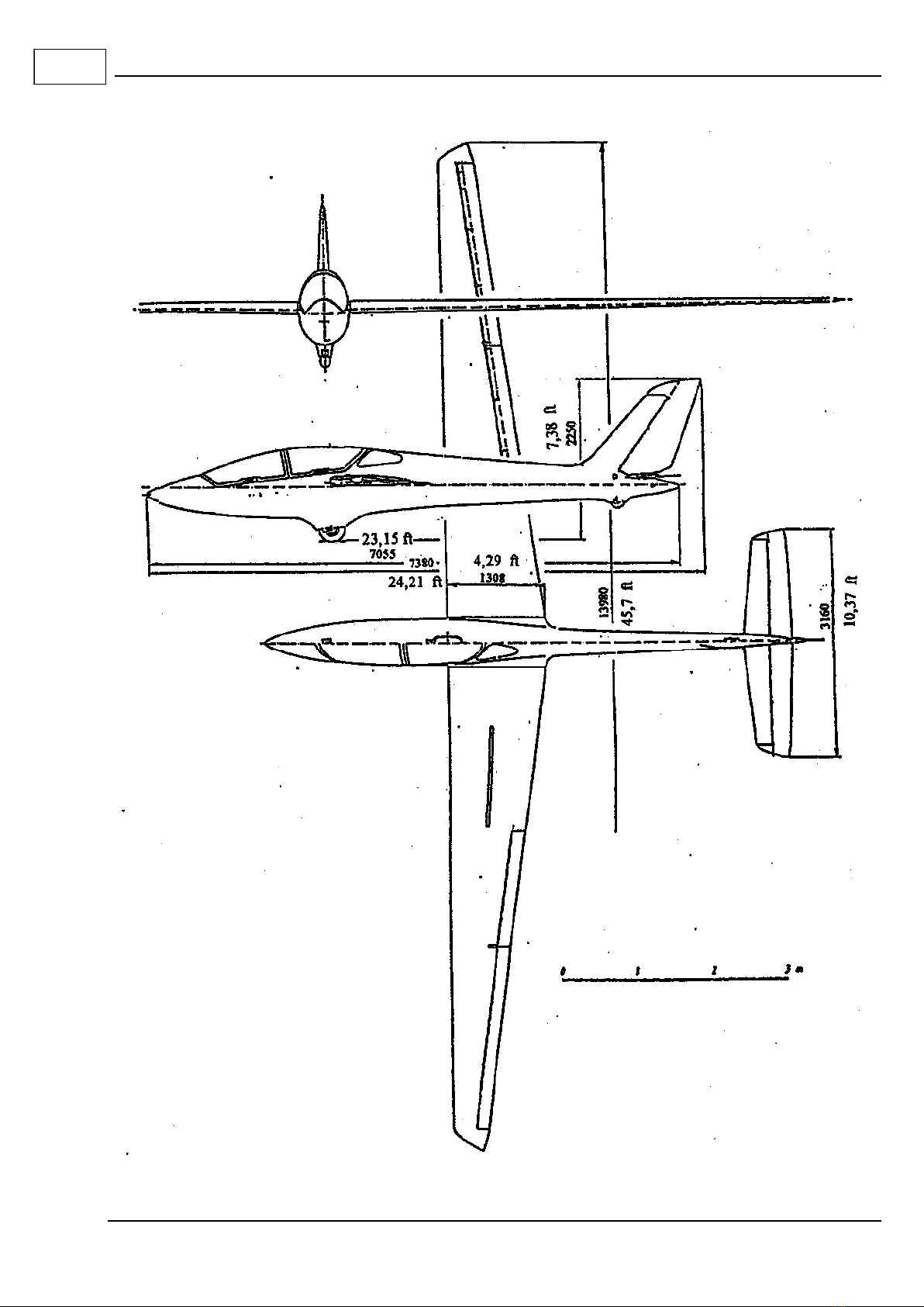
1.4 Glider description and technical data.
MDM-1 „FOX” is a two-seat performance aerobatic glider, mid-wing layout with conventional tail-unit
arrangement. The structure of glass/epoxy and carbon/epoxy composite.
Wings :
Two-panel planform of considerable taper. Monospar structure with an auxiliary spar, and sandwich
type skin. Spar of double-C shape. Monoplate air brake extended on wing upper surface only.
Large span, constant chord Friese type aileron , split in two panels, mass-balanced and suspended on 7
hinges.
Overlapping-type spar connection with two horizontal bolts extending up to rear fittings, connects also
wings to fuselage.
3
Rev. 3/ July 1998

MDM-1 „FOX” FLIGHT MANUAL
1.3
Issue III
Fuselage :
Monocoque, sandwich structure with integral fin. The seat pans bonded permanently. Two-piece, side
hinged canopy opening sidewards to the right.
In fuselage nose the total pressure port and air intake for air vent are provided, static pressure ports on
the fuselage nose both sides.
The transceiver antenna installed in the fin.
The towing hook installed in the front fuselage part.
The winch-launching hook installed in front of the main undercarriage.
At front seat, on both sides on cockpit floor, the balancing weights are installed.
Pedals at front seat - adjustable with a grip (item 11 in Fig. 7.1)
Back rest of front seat - adjustable by changing the position of back rest support (item 23 in Fig. 7.2)
Tail unit :
Stabilizer, elevators and rudder of sandwich structure, control surfaces aerodynamically-, and mass-
balanced.
Control system :
Elevator and aileron control system - push rod type.
Rudder control system - cable type.
Air brake control system, in wings of push rod type and in fuselage - combined.
The elevator system equipped with a spring trimming device operated with a lever at the control stick
base, at front seat.
Undercarriage :
Fixed undercarriage (with main and tail wheels), faired. Hydraulic disc brake on main wheel, actuation
coupled with air brake.

MDM-1 „FOX” FLIGHT MANUAL
1.4
Issue III
M a i n t e c h n i c a l d a t a :
Span
14.0
0
[m]
45.93 [ft]
Length (up to rudder top edge) 7.38 [m] 24.21 [ft]
Height (in flight attitude)
2.25 [m]
7.38 [ft]
Wing dihedral 0
Wing area 12.34 [m2
]
132.8 [ft2
]
Aspect ratio 15.88
Root chord 1.308 [m]
4.291 [ft]
Mean Standard Chord (MSC) (1) 0.971 [m] 3.186 [ft]
Wing profile NACA 641 412
Tailplane span 3.160 [m] 10.37 [ft]
Tailplane area 1.873 [m2] 20.2 [ft2
]
Tailplane profiles NACA 63
1
012
÷
63 006 mod.
Fin and rudder area 1.123 [m2
]
12.09 [ft2
]
Fin and rudder profiles NACA 63
2
015
÷
63
1
012
C.G. position (empty glider) 620÷645 [mm]
aft of
Datum Plane
(2)
24.43÷25.41 [in]
Nominal empty weight:
-
without balancing weights
-with balancing weights (2x5.5= 11 kG)
350 [kG]
361 [kG]
772 [lb]
796.3 [lb]
Max. weight of structural non-lifting parts
(wing-less glider)
165 [kG] 364 [lb]
Max. in-flight weight 530 [kG] 1168 [lb]
C.G. position (in-flight) 213÷379 [mm] aft of DP 8.40÷14.93 [in] aft of DP
Position of load components:
Instrument panel at front seat 1580 [mm] fore of DP 62.25 [in] fore of DP
Balancing weights
1520 [mm] fore of DP
59.89 [in] fore of DP
Pilot on front seat
950 [mm] fore of DP
37.43 [in] fore of DP
Instrument panel at rear seat 440 [mm] fore of DP 17.34 [in] fore of DP
Pilot on rear seat
60 [mm]
aft of DP
2.36 [in] aft of DP
Luggage not allowed
Max. wing surface loading 42.54 [kg/m2] 8.72 [lb/ft2]
Limit manoeuvring load factors +7 / -5
Limit manoeuvring load factors for solo flying
(max. useful load 100 kG)
+9 / -6
(1) Mean Standard Chord (MSC) - chord of aerodynamically equivalent rectangular wing
(2) Datum Plane (DP) - vertical plane passing through the wing leading edge
4
4
1
7
1
7
7
7
7
Rev. 7/ June 2019

MDM-1 „FOX” FLIGHT MANUAL
1.5
Issue III
1.5 Three-view drawing.

MDM-1 „FOX” FLIGHT MANUAL
2.1
Issue III
Section 2
2. LIMITATIONS
2.1. Introduction
2.2. Airspeed
2.3. Airspeed indicator markings
2.3A. Electronic accelerometer markings
2.4. Power plant, fuel and oil. - NOT APPLICABLE
2.5. Power plant instrument markings. - NOT APPLICABLE
2.6. Weight
2.7. Centre of gravity
2.8. Approved manoeuvres
2.9. Manoeuvring load factors
2.10. Flight crew
2.11. Kinds of operation
2.12. Minimum equipment
2.13. Aerotow and winch launching
2.14. Other limitations
2.15. Limitations placards
7
7
Rev. 7/ June 2019

MDM-1 „FOX” FLIGHT MANUAL
Appr. 2.2
Issue III
2.1 Introduction.
Section 2 includes operating limitations, instrument markings and basic placards informing on
limitations necessary for safe operation of the glider, its systems and standard equipment.
The limitations contained in this Section and in Section 9 have been approved by Civil Aircraft
Inspection Board.
2.2 Airspeed.
Airspeed limitations and their operational significance, used in this Manual are shown below:
Speed (IAS) [km/h] [kt] Remarks
VNE Never exceed speed 282 152 Do not exceed this speed in any operation
and do not use more than 1/3 of control
deflection
VRA Rough air speed 225 122 Do not exceed this speed except in smooth
air and then only with caution. Examples
of rough air are: lee-wave rotor,
thunderclouds etc.
VA Manoeuvring speed 214 116 Do not make full or abrupt control
movements above this speed, because
under certain conditions the glider may be
overstressed by full control movement.
VW Maximum winch-
launching speed
150 81 Do not exceed this speed during winch-
launching.
VT Maximum aerotowing
speed
150 81 Do not exceed this speed during
aerotowing.
WARNING: In high altitude flight, the true airspeed (TAS) is higher than value indicated by
airspeed indicator (IAS). To maintain the safe margin against the flutter limit
related to true airspeed value, VNE must be reduced with altitude to values specified
in the following table.
Flight altitude Never exceed
speed V
NE
IAS
Flight altitude Never exceed
speed V
NE
IAS
[m]
[km/h]
[ft]
[kt]
0-3000 282 0-10000 152
4000 267 13000 145
5000 253 16000 138
5500 246 18000 133
7
Rev. 7/ June 2019

MDM-1 „FOX” FLIGHT MANUAL
Appr. 2.3
Issue III
2.3 Airspeed indicator markings
Airspeed indicator markings and their colour-code significance are shown below:
Marking (IAS) value or range Significance
[km/h]
[kt]
Green arc 92 ÷ 225 50 ÷ 122 Normal operating range.
Lower limit is 1.1 VS1 at maximum weight and
most forward C.G.
Upper limit is Rough Air speed 1.
Yellow arc 225 ÷ 282 122 ÷ 152 Caution operation range.
Manoeuvres must be conducted with caution
and in smooth air only.
Upper limit is Never Exceed speed.
Red radial line 282 152 Maximum speed for all operations
Yellow triangle 115 62 Approach speed at maximum weight.
2.3A Electronic accelerometer markings
Marking
Value
Significance
Red diode on front instrument panel
and
(TL-3424) WARNING MAX or WARNING MIN
message on upper part of instrument display.
(MGL INFO-1) Pointer on yellow field and
acceleration value highlighted by a yellow flashing
background
+7g / -5g
Maximum allowed
(positive / negative)
manoeuvring load factor
with two person crew.
Red diode on front instrument panel
and
(TL-3424) ALARM MAX or ALARM MIN
message on upper part of instrument display.
(MGL INFO-1) Pointer on red field and
acceleration value highlighted by a red flashing
background
+9g /
-
6g
Maximum allowed
(positive / negative)
manoeuvring load factor
with one person crew.
(allowed take-off weight
450kG)
2.4 Power-plant - NOT APPLICABLE
2.5 Power-plant instrument markings - NOT APPLICABLE
1 Leaving markings for the upper airspeed limit of the Normal Operating Range at VA =214 km/h (116kt), i.e. at a value
lower than allowed for the design VRA =225 km/h (122kt), is considered conservative and accepted for gliders S/N up to
251 inclusive.
7
7
7
Rev. 7/ June 2019

MDM-1 „FOX” FLIGHT MANUAL
Appr. 2.4
Issue III
2.6 Weight
Maximum take
-
off
& landing
weight
530 [kG] 1168 [lb]
Maximum
take
-
off &
landing weight
for the range of manoeuvring load factor
extended to +9/ -6 g in solo flight
450 [kG] 992 [lb]
Maximum empty weight without balancing weights
350 [kG] 772 [lb]
Maximum empty weight with balancing weights
361 [kG] 796 [lb]
Maximum weight of all non
-
lifting parts
165 [kG] 364 [lb]
Maximum weight in baggage compartment
0 [kG] 0 [lb]
2.7 Centre of gravity.
C.G range (in flight): 22 through 39
213 through 379
(8,40 14,93)
per cent of MSC.
[mm] aft of Datum Plane
[in]
C.G. range (empty glider) : 620 ÷ 645
(24.4 ÷ 25.4)
[mm] aft of Datum Plane
[in]
2.8 Approved manoeuvres.
This glider is certified in Aerobatic Category.
Approved aerobatic manoeuvres, together with recommended entry airspeeds for particular manoeuvres
are given in FM Section 4.
2.9 Manoeuvring load factors
Limit load factors +7/-5
Limit load factors for solo flying, crew weight below 100 kg (220 lb) +9/-6
2.10 Flight crew
The crew consists of one, or two persons.
Solo flying on front seat only.
1
1
7
4
4
Rev. 7/ June 2019
7

MDM-1 „FOX” FLIGHT MANUAL
Appr. 2.5
Issue III
2.11 Kinds of operation
Flying in anticipated icing conditions and night flying - PROHIBITED.
Cloud flying - ALLOWED,
provided pilot and glider meet National Regulations.
2.12 Minimum equipment
Minimum equipment of the glider depends on the intended type of operation and consists identification
of components, location and range of indication (where specified) as shown below
component & location
range of indication
remarks
Type of operation: normal (soaring) flight
airspeed indicator
,
at front seat
300 [km/h] (160 [kts])
altimeter,
at front seat
5-point safety harness,
at front
-
, and at rear seats
parachute or back cushion:,
for each crew member
cushion thickness:
8 cm (3 in) for the front seat,
2 cm
(
1 in
)
for
the
rear seat
Type of operation: aerobatic flight
(in addition to the above)
accelerometer
,
at front seat
9
/
-
6 g
for dual aerobatic instruction, an accelerometer required in both instrument panels
NOTE: The regulations in the country of registry may mandate the installation of additional
equipment items (compass, transceiver, etc.) which must be complied with for the
intended type of operation.
2.13 Aerotow and winch-launching
For aerotow, the nylon towing cable of 40 ÷ 60 [m] (130 ÷ 195 [ft]) length, with safety link of
677 [daN] (1525 [lb]) ± 10 per cent strength shall be used.
For winch-launching, the cable with safety link of 677 [daN] (1525 [lb]) ± 10 per cent strength shall be
used.
Maximum aerotow and winch-launching speed is 150 [km/h] (81 [kt]).
Autotow-launching is PROHIBITED.
2.14 Other limitations
Cross-country flight, both in free and in aerotowed flight, in one-person crew only.
7
7
Rev. 7/ June 2019

MDM-1 „FOX” FLIGHT MANUAL
Appr. 2.6
Issue III
2.15 Limitations placards.
The following placards should be placed in a visible place in the cockpit:
Flight altitude [m] 0-3000 4000 5000 5500
V
NE
[km/h]
282 267 253 246
Flight altitude [ft] 0-10000 13000 16000 18000
V
NE
[kt] 152 145 138 133
LOADING PLAN
Pilot with parachute weight
Balancing
Limit
front seat rear seat weights
manoeuvring
minimum maximum load factor
[kG] [lb] [kG] [lb] [kG] [lb] [kG] [lb]
55 121 89 196 0 0 2x5.5 2x12.1
+ 9 / - 6
70 154 100 221 0 0 0 0
70 154 110 243 0 0 0 0
55 121 110 243 55 121 0 0 + 7 / - 5
55 121 70 154 110 243 0 0
Solo flying on front seat only
Installation of balancing weights (2*5.5 kG) acc. to FM item 7.2 and Fig. 7.1.
LIMITATIONS
1. Night flying prohibited
2. Cloud flying allowed,
provided pilot and glider meet National Regulations
3. Flying in anticipated icing conditions prohibited
4. Aerobatics allowed,
according to Flight Manual item 4.5.9
For aerotowing, use 40÷60 m (130÷195 ft)
long nylon cable, with safety link
of 677 daN (1525 lb) ±10 % strength
SPEED LIMITATION
IAS [km/h]
[kt]
VNE 282 152
VRA 225 122
VA 214 116
VT 150 81
For winch launching,
use cable with safety link
of 677 daN (1525 lb) ±10 % strength
BEFORE FLIGHT
- Check cockpit, take a seat
- Adjust pedals, back rest and balancing weights
- Check full deflection of control surfaces, retract air brake
- Set altimeter to zero reading
- Fasten and tighten safety belts
- Check setting of elevator trim
- Lock both canopies, perform communications check
7
7
7
4
Rev. 7/ June 2019

MDM-1 „FOX” FLIGHT MANUAL
2.6A
Issue III
2.15 Limitations placards.
The following placards should be placed in a visible place in the cockpit:
LIMITATIONS
1. Night flying prohibited.
2. Cloud flying allowed,
provided pilot and glider meet National Regulations.
3. Flying in anticipated icing conditions prohibited.
4. Aerobatics allowed,
according to Flight Manual item 4.5.9
For aerotowing, use 40÷60 m (130÷195 ft)
long nylon cable, with safety link
of 677 daN (1525 lb) ± 10% strength
For winch launching,
use cable with safety link
of 677 daN (1525 lb) ± 10% strength
BEFORE FLIGHT
Check cockpit, take a seat
Adjust pedals, back rest and balancing weights
Check full deflection of control surfaces, retract air brake
Set altimeter to zero reading
Fasten and tighten safety belts
Check setting of elevator trim
Lock both canopies, perform communications check
SPEED
LIMITATION
IAS
[km/h]
[kt]
VNE 282 152
VRA 225 122
VA 214 116
VT 150 81
LOADING PLAN
Pilot with parachute weight
Balancing
Limit
front seat
rear seat
weights
maneuvering
minimum
[kG] [lb]
maximum
[kG] [lb]
[kG] [lb]
[kG] [lb]
load factor
[g]
55
121
89
196
0
0
2x5.5
2x12.
2
+ 9 / - 6
70
154
100
221
0
0
0
0
70
1
54
110
243
0
0
0
0
55
121
110
243
55
121
0
0
+ 7 /
-
5
55
121
70
154
110
243
0
0
Solo flying on front seat only
Installation of balancing weights according to item 7.2 and Fig. 7.1 - F.M.
Flight altitude [m] 0-3000 4000 5000 5500
V
NE
[
km/h
]
282
267
253
246
Flight
altitude
[ft] 0-10000 13000 16000 18000
V
NE
[kt] 152 145 138 133
Rev. 7/ June 2019
7
Rev. 7/ June 2019

MDM-1 „FOX” FLIGHT MANUAL
3.1A
Issue III
Section 3
3. EMERGENCY PROCEDURES
3.1. Introduction
3.2. Canopy jettison
3.3. Bailing out
3.4. Stall recovery
3.5. Spin recovery
3.6. Spiral dive recovery
3.7. Power-plant failure - NOT APPLICABLE
3.8. Fire
3.9. Other emergencies

MDM-1 „FOX” FLIGHT MANUAL
Appr. 3.2
Issue III
3.1 Introduction.
Section 3 provides the exact procedures for coping with emergencies that may occur.
3.2 Canopy jettison.
1. Pull back with both hands simultaneously the red lever on the right hand canopy side and the canopy
opening lever on the left hand side.
2. Push the canopy upwards, if necessary.
WARNING: Both pieces of canopy cannot be jettisoned by one person. In case of training or
passenger flight, each crew member shall be familiar with canopy jettison and bailing
out procedures.
3.3 Bailing out.
1. Jettison the canopy.
2. Release the safety belts.
3. Holding at cockpit boards, pull up legs and bail out.
4. If the glider is rotating, e.g. spinning, bail out towards the centre of rotation.
3.4 Stall recovery.
The glider, both in straight flight and in turn, gives the clear stall warning in the form of perceptible
vibrations, appearing at the sufficient margin when the critical incidence angle is approached.
The nose of stalled glider gently drops down below the horizon.
The aileron control remains efficient till to the stall.
Altitude loss in symmetrical stall ranges 20 through 30 [m] (65 through 98 [ft]).
The lateral balance maintained with aileron, with stick pulled completely back leads to a deep stall
condition associated with a considerable sinking (approx. 8 [m/s], i.e. 16 [kt]).
The recovery is easy and immediate by pushing the stick forwards slightly beyond the neutral, or by
leaving the controls free.

MDM-1 „FOX” FLIGHT MANUAL
Appr. 3.3
Issue III
3.5 Spin recovery.
The spinning is unstable. During the spinning, the oscillations of both pitch and rotational speed may
occur.
The recovery delay reaches its maximum value in the second turn, where both the acceleration of
autorotation and spin flattening appear. The delay does not exceed one turn.
The normal recovery procedure:
1. Deflect the rudder opposite to autorotation.
2. Release the stick forwards slightly beyond the neutral.
3. Neutralize the rudder.
4. Recover the glider out of diving.
NOTE: Deflection of the aileron towards spinning increases the delay.
Deflecting the aileron opposite to spinning results in transition from spinning into a
spiral slide.
3.6 Spiral dive recovery.
1. Deflect the aileron and rudder opposite to rotation.
2. When the symmetrical flight is obtained, neutralize the aileron and rudder.
3. Decrease the airspeed.
3.7 Power-plant failure - NOT APPLICABLE
3.8 Fire.
NOT EXPECTED.
3.9 Other emergencies.
NO OTHER EMERGENCIES KNOWN.
Table of contents
Popular Aircraft manuals by other brands

Independence paragliding
Independence paragliding STRIKER manual

Gradient
Gradient bigoldern3 user manual

SusiAir
SusiAir PILATUS PORTER PC6 Maintenance Program

Piper Aircraft Corporation
Piper Aircraft Corporation Cherokee Series Service manual

NIVIUK GLIDERS
NIVIUK GLIDERS IKUMA Series user manual

SUP’AIR
SUP’AIR LEAF3 user manual