55-10
Page 4 All
EFFECTIVITY:
CIRRUS AIRPLANE MAINTENANCE MANUAL MODELS SR22 AND SR22T
15 Jun 2010
CAUTION: When cutting bonding flanges, another technician should support the
horizontal stabilizer to minimize any shifting of weight that could
stress the flanges at remaining bond lines.
Also, the second technician should apply compressed air to bond line
during cutting procedure to prevent heat build-up from potentially
scorching the airplane surfaces, and provide debris clean-up.
Use caution when cutting to not cause excessive damage to the hori-
zontal stabilizer and/or fuselage bonding flange. If damage exceeds
repair specifications, contact Cirrus Design for disposition.
To prevent binding during the removal process, begin cutting with 90°
oscillating tool at the bottom bond line.
3Using 90° oscillating tool with cutting disc at bond line, position disc flush with sur-
face of horizontal stabilizer. Apply compressed air simultaneously to bond line when
cutting. Cut horizontal stabilizer section from empennage.
4If necessary, use blade oscillating tool to cut remaining bond line. Once bond line
has been separated, repeat both cutting procedures on upper bond line.
5Repeat cutting procedures on opposite side.
6Remove horizontal stabilizer from airplane.
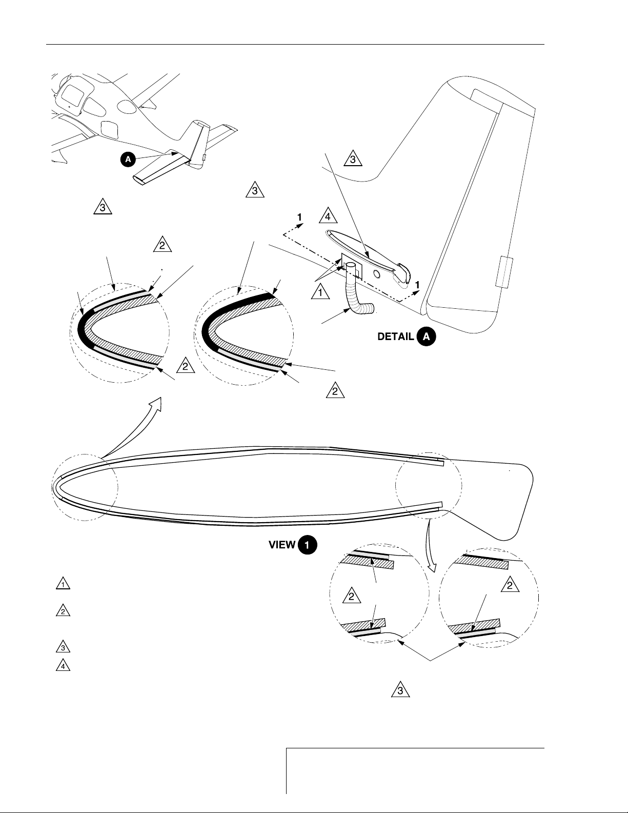
(k) Horizontal Stabilizer Removal Method #2: Remove horizontal stabilizer. (See Figure 55-
102)
1Draw an offset line 1.0 inch (2.54 cm) from horizontal stabilizer root around entire
surface of horizontal stabilizer. Repeat on opposite side.
CAUTION: Use caution when cutting to not cause excessive damage to the fuse-
lage bonding flange. If damage exceeds repair specifications, contact
Cirrus Design for disposition.
2Using reciprocating saw with 6 inch (15 cm) blade at offset line, cut horizontal stabi-
lizer section from empennage. Repeat on opposite side.
3Using reciprocating saw, cut through spar of remnant to remove core.
4Position cutting end of wedge between aft remnant and upper fuselage flange.
5Strike back of wedge forward to leading edge of remnant.
6Position second wedge at same position on opposite side of empennage and repeat
striking action. Alternate between driving both wedges forward to leading edge of
remnant. Repeat remnant separation at lower flange surfaces.
7If leading edge of remnant is still adhered to fuselage flange, alternately position flat
end of wedge to sides of remnant and strike with hammer until remnant is loosened.
Remove horizontal stabilizer composite remnant.