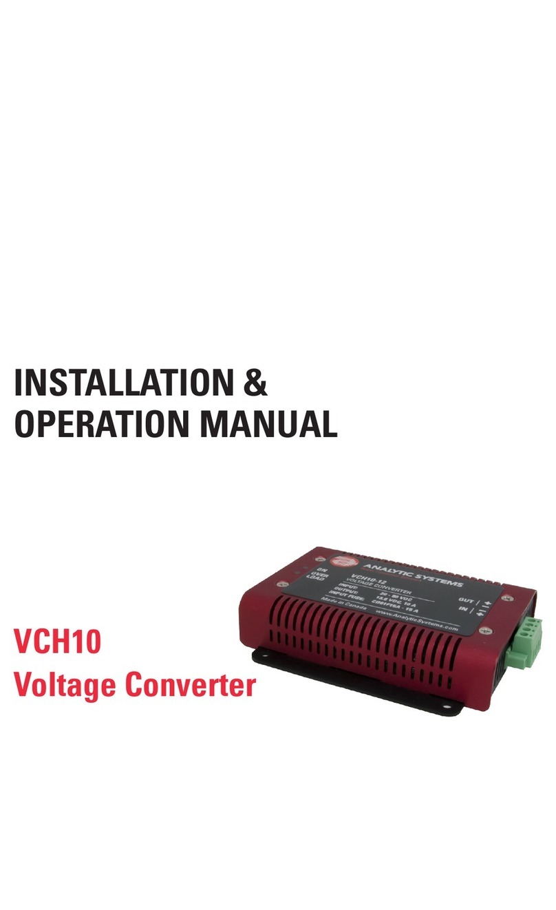
MDS Power VTCi320 User manual

INSTALLATION &
OPERATION MANUAL
VTCi320
INTELLIGENT
VOLTAGE
CONVERTER
T.514.369.4919 TF. 800.931.4919
www.mdspower.com

2
VOLTAGE CONVERTERS
IMPORTANT SAFETY INSTRUCTIONS
SAVE THESE INSTRUCTIONS — This manual contains important safety and operating
instructions for the voltage converter
VOLTAGE CONVERTER PRECAUTIONS
1. Do not expose the voltage converter to rain or snow unless it is a sealed model.
2. Use of an attachment not recommended or sold by the manufacturer may result in a
risk of re, electric shock, or injury to persons.
3. Do not disassemble the voltage converter. If service or repair is required, return it to
the manufacturer or an authorized service center. Incorrect reassembly may result in
a risk of re or electric shock. Voltages up to 350 volts are present inside the voltage
converter any time it is connected to input power, even if it is switched OFF.
4. To reduce risk of electric shock, disconnect the voltage converter from the input
power before attempting any maintenance or cleaning. Switching the voltage con-
verter to OFF will not reduce this risk.
5. Never place the voltage converter directly above a battery; gases from the battery
will corrode and damage the voltage converter.
6. Never allow battery acid to drip onto the voltage converter.
MEDICAL EQUIPMENT NOTICE
This unit is not recommended for use in life support applications where failure or
malfunction can be reasonably expected to cause failure of the life support device
or to signicantly affect its safety or effectiveness. This unit is not recommend the
use of any of its products in direct patient care. Examples of devices considered to
be life support devices are neonatal oxygen analyzers, nerve stimulators (whether
used for anesthesia, pain relief, or other purposes), auto-transfusion devices,
blood pumps, debrillators, arrhythmia detectors and alarms, pacemakers,
hemodialysis systems, peritoneal dialysis systems, neonatal ventilator incubators,
ventilators for both adults and infants, anesthesia ventilators, and infusion pumps
as well as any other devices designated as “critical” by the U.S. FDA.
WARNING: Do not connect this unit to a battery. It does not have the circuitry
or programming to properly charge a battery. Both the voltage converter and the
battery could be damaged or destroyed!

3
TABLE OF CONTENTS
• Front Cover, Product Photo and Title
• Product Warnings and Advisories
• Table of Contents
• Introduction
• Box Contents
• Main Parts
• Operation
• Installation
• Front Panel Adjustments
• Maintenance
• Dry Contact Relay
• Denitions and Abbreviations
• Troubleshooting
• Specications
• Warranty
Revised - March 31, 2020

4
Introduction
Box Contents
The box you have received should contain the following:
• One VTCi320 Intelligent Voltage Converter
• One USB cable
• This user guide
• One Warranty Registration Card
If anything is missing or damaged please contact your dealer for a replacement
The VTCi320 series Intelligent DC-source Voltage Converter operates from 100 to 350 VDC to
deliver up to 300 watts of precision power to supply your 12, 24, or 48 volt electrical systems.
Internally, LLC Resonant Converter technology allows Zero Voltage/Zero Current switching on the
primary or high voltage side of the main power transformer. Multiple stages of ltering ensures
ultra quiet operation for minimum electromagnetic interference (EMI) near sensitive radio
frequency communication equipment.
The unit’s front panel features eight-dual color LEDs to clearly indicate operating condition and
alarm states. Other safety features include over temperature derating with shutdown, current
limiting, output short circuit protection, input under voltage shutdown and output over voltage
protection all with automatic recovery.

5
Main Parts
1. Power Button
2. MicroUSB Port
3. Indicator LEDs
4. Program Button
5. Select Button
6. DC Output Connection: 2x Phoenix
VDFK Terminal Block Connetions (Red:
Positive, Black Negative)
7. Chassis Ground Stud
Front Panel
2
3
7
6
1
5
4
Rear Panel (Not shown)
1. AC Power Input Connection:
1ft/30cm Type-D #14AWG Stranded
Input Leads (Red: Positive, Black
Negative)
2. Input Fuse: 6.3 Amp-400 VDC fuse

Operation
The VTCi320 Voltage Converter is designed for simple operation. It is intended to operate fully
unattended and will attempt to recover from any fault, including Over-Temperature, Low Input
Voltage, Input Power Failure and Overload.
TO OPERATE
1. Press the Power Button on the unit’s front panel. It will start glowing.
2. The voltage converter will go through its startup sequence. All 6 microprocessor-
controlled LEDs ash red and then green. When the Power Button starts glowing, the
sequence is complete.
3. The VTCi320 will automatically supply the load with the voltage indicated on its label for
as long as the load is connected.
4. The Indicator LEDs can be used to determine the amount of current being drawn by the
load. See the diagram below.
BLINKING
75
CURRENT > 11-39%
IP TEMP
25
DEV
75
FAIL
FLT
LO V
OP
50
CURRENT = 100%
IP
POL
TEMP
25
DEV
75
FAIL
FLT
LO V
OP
50
CURRENT >85%
IP TEMP
25
DEV
75
FAIL
FLT
LO V
OP
50
CURRENT > 40-59%
IP TEMP
25
DEV
75
FAIL
FLT
LO V
OP
50
CURRENT < 10%
IP TEMP
25
DEV
75
FAIL
FLT
LO V
OP
50
CURRENT > 60-84%
AC TEMP
25
DEV
CH
75
FAIL
FLT
LO V
OP
50
EQ
PS
TO END OPERATION
1. Press the Power Button on the unit’s front panel.
2. The voltage converter will beep and the LED indicators will stop glowing.
3. When all the LEDs are dim, the unit is safe to disconnect from the load and power source.
4. The unit can now be safely serviced or put into storage.
TO INSTALL
1. Connect the Voltage Converter to the load before con-
necting the input power.
2. Connect the Power Supply to the input power. The IP
LED should illuminate indicating it is receiving power.
IP TEMP
25
DEV
75
FAIL
FLT
LO V
OP
50
6

Installation
MOUNTING
When mounting your unit, take the
following into consideration:
• The indicator LEDs and front panel
controls should be easy to see and
access.
• There are at least 2 inches of clear-
ance all around the converter for air
circulation and heat dissipation.
• The load should be close enough for
to easy connection and to prevent
trampling of the wiring.
• If there is possibility of water drippage, such as if the unitis in a marine environment,
install the optional drip shield above the unit.
Red Input Lead - Positive DC Terminal
Black Input Lead - Negative DC Terminal
Normally these leads should be adequate to connect to the DC power source, however, if you
must extend the leads, be sure to:
• Use the smallest extension length possible.
• Use a good quality (typeTEW) wire
• Use no less than 14 gauge conductors.
• Splice and solder the joints and protect the joints with heat shrink tubing.
INPUT POWER CONNECTION
The unit is equipped with two 3-foot/1 meter Type-D Stranded AWG14 wire leads to serve as
a DC Input Connection. Connect these leads to the DC power source in the polarity indicated.
CAUTION: THE VOLTAGE CONVERTER MUST BE TURNED OFF BEFORE CONNECTING
OR DISCONNECTING ANYTHING TO IT.
To prevent the risk of high voltage electric shock, the voltage converter must be OFF before
connecting or disconnecting anything to the unit.
7

DC OUTPUT CONNECTION
This unit is equipped with a pair of Phoenix VDFK Terminal block connectors to serve as a DC Output
connection for connection to DC loads. The connection can support up to two connected loads. The
polarity for these connections can be found on the unit’s front panel label.
Connector Color Polarity
Red Output Positive
Black Output Negative
CAUTION: DO NOT CONNECT THE LOAD IN THE REVERSE POLARITY!!
This will activate the reverse connection protection which will blow the output fuse(s) inside the
unit in order to protect the device. The unit will be inoperable until these fuses have been replaced.
Max. Output Current 24.00 A 15.00 A 9.30 A 5.90 A 3.70 A
American Wire Gauge #8AWG #10AWG #12AWG #14AWG #16AWG
Max. Output Current 2.30 A 1.50 A 0.92 A 0.58 A 0.23 A
American Wire Gauge #18AWG #20AWG #22AWG #24AWG #28AWG
IMPORTANT: OUTPUT CONNECTION WIRING USED MUST BE APPROPRIATELY
RATED FOR THE EXPECTED OUTPUT CURRENT.
See specications or your unit’s label for the maximum output current and the table below for
usable wire gauges.
The PRG and SEL buttons on the front panel currently have no function. However, in a future
rmware update they will add the capability to adjust the output voltage over a range from
nominal to +17% (-0V to +2V for a 12V model for example). Subscribe to our newsletter to be
notied when this update becomes available.
Front Panel Adjustments
8

Maintenance
Dry Contact Relay
This voltage converter requires no maintenance other than the occasional wipe down to
remove dust that could reduce its ability to dissipate heat. Carefully blow air through the
cooling vent to remove any dust buildup inside the unit.
The voltage converter can be tted with a 1-amp dry contact relay to indicate its status to a
monitoring system. It has both a normally-open and normally-closed contact which changes
state depending on the presence or absence of charging voltage on the output and is
independent of the microprocessor.
If the unit is producing voltage on the output, the normally closed contact will be closed and
there will be an electrical connection between NC and COM. If the voltage on the output goes
to zero, the contact will change state. The Normally Open contact operates exactly in the
reverse of the Normally Closed contact.
Abbreviations and Denitions
We use a number of abbreviations on the labels to save space. Here are the full words corre-
sponding to each abbreviation along with common terms and their denitions:
Abbreviation Full Name Meaning
DEV Device Refers to the Device. Used together with the Fault
(FLT) LED to indicate a fault with the device.
FLT Fault Used to indicate a problem with the device (DEV)
IP Input Power Refers to the presence of DC power on the input
connection.
OP Output Power Refers to the presence of DC power on the output
connection.
TEMP Temperature Used to indicate that the Device is too hot.
LO V Low Voltage Used to indicate that the Input Voltage is too low.
FAIL Failure Used to indicate that the device needs repair or
replacement.
PRG Program Button used to initiate the Programming Mode (not
used)
SEL Select Button used to make choices during Programming
Mode (not used)
9

Troubleshooting
The VTCi320 is designed to provide years of reliable service and to auto-recover in the
event of an operational failure. In the event of malfunction, the unit is tted with eight LED
indicators and an audible alarm to help diagnose the cause of the issue. Below is a list of
potential issues, and how to repair them.
NO DC POWER DETECTED
IP TEMP
25
DEV
75
FAIL
FLT
LO V
OP
50
No DC Power Detected
The converter is not detecting any power on the input. Using a
multimeter, check that the power source is working. Check that
the input fuse hasn’t blown. If the fuse is blown, replace it with
the recommended fuse listed on the label. If the LEDs still do not
glow, then there is likely an internal failure and the unit will have
to be returned for service.
Low Input Voltage Indication
The voltage converter has detected that the input voltage has
dropped below the minimum level needed for normal operation.
The unit will shut off and wait for the voltage to recover.
OVERTEMP
IP TEMP FAILLO V
IP TEMP
25
DEV
75
FAIL
FLT
LO V
OP
50
Over Temperature Indication
The voltage converter has detected that its internal temperature
is above safe operating limits. It will shut off until the
temperature has returned to normal limits. If this happens
frequently, the unitmay need to be remounted for better air
circulation.
FAULT INDICATORS BLINKING
Converter Failure Indication
The microprocessor has detected a condition that prevents the
converter from operating. Try disconnecting the input power
and re-connecting it. If this does not clear the fault, the cause is
likely an internal component failure and the unit will have to be
returned for service.
CONVERTER FAILED
25
DEV
75
FLTOP
50
IP TEMP FAILLO V
OVERLOAD/SHORT CIRCUIT
IP TEMP
25
DEV
75
FAIL
FLT
LO V
OP
50
Output Overload/ Short Circuit
If the voltage converter is overloaded and the output voltage
has dropped drops below nominal voltage range for the unit, the
output will cycle on/off until the overload condition is removed.
LOW VOLTAGE
25
DEV
75
FLTOP
50
IP TEMP FAILLO V
10

Specications
Mechanical
Length 10.7 in. / 27.2 cm
Width 8.0 in. / 20.3 cm
Height 3.25 in. / 8.3 cm
Clearance 2.0 in. / 5.0 cm all around
Weight 6.2 lb / 2.8 kg
Material and Finish Marine-grade black anodized aluminum
Fasteners 18-8 Stainless steel
Mounting Vertical or horizontal mounting
Output Connection DC Output: 2x sets of Phoenix VDFK Terminal Block (Red and Black)
Input Connection AC Input: Type-D #14AWG Stranded Input Leads (Red: Positive,
Black Negative)
Other Connections Data/Communications: MicroUSB port
Environmental and Safety
Operating Temperature Range -25°C+ to +40°C (-40°C to +55°C Optional)
Storage Temperature Range -55°C to +85°C
Humidity 0 - 95% Relative Humidity (non-condensing)
Emissions Complies with FCC Class B, Part 15
Isolation Input-Output, Input-Case, Output-Case: > 1500 VDC
Audible Noise None (Ø db)
Duty Cycle Continuous
Warranty Five Years Parts and Labor
Safety Built to meet ABS, CE, UL458 and CSA 22.2.107.1
* Specications subjects to change without notice.
Input
Nominal Voltage 100 - 350 VDC
Maximum Input Amps 4 Amps w. Inrush Protection
Input Fuse 6.3 Amp 400 VDC fuse
Output
Nominal Voltage 12 VDC 24 VDC 48 VDC
Voltage Range (VDC)** 12.0-15.5 VDC 24.0-31.0 VDC 48.0-62.0VDC
Output Current 20 A 10 A 8 A
Peak Amps 25 A 12.5 A 6.25 A
Efciency 90% @ Full Load
11

800-931-4919
514-369-1919
order@mdspower.com
www.mdspower.com
DESIGNED AND BUILT IN CANADA
Table of contents
Other MDS Power Media Converter manuals
Popular Media Converter manuals by other brands

VBrick
VBrick 9000 Series Getting started guide

Axxcelera Broadband Wireless
Axxcelera Broadband Wireless AB-100 user manual

Ambery
Ambery 4-Way Operation manual

Mitsubishi Electric
Mitsubishi Electric MELSEC iQ-R Series user manual

TEAC PROFESSIONAL
TEAC PROFESSIONAL Tascam LA-80MKII owner's manual

Transition Networks
Transition Networks J/E-CF-01 user guide