MDT Technologies BE-04001.01 Owner's manual

MDT technologies GmbH • 51766 Engelskirchen • Papiermühle 1
1
07/2013
Technical Manual
MDT Universal Interfaces
BE – 02001.01
BE – 04001.01
BE – 06001.01

Technical Manual Universal Interface BE
MDT technologies GmbH • 51766 Engelskirchen • Papiermühle 1
2
1Content
1Content.................................................................................................................................................2
2Overview.............................................................................................................................................4
2.1Overviewdevices...........................................................................................................................4
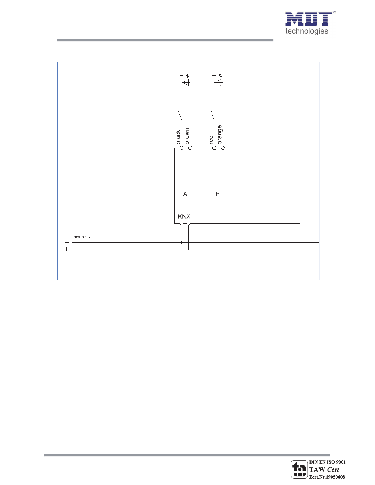
2.2Exemplarycircuitdiagrams..........................................................................................................4
2.3Usage&areasofuse.....................................................................................................................6
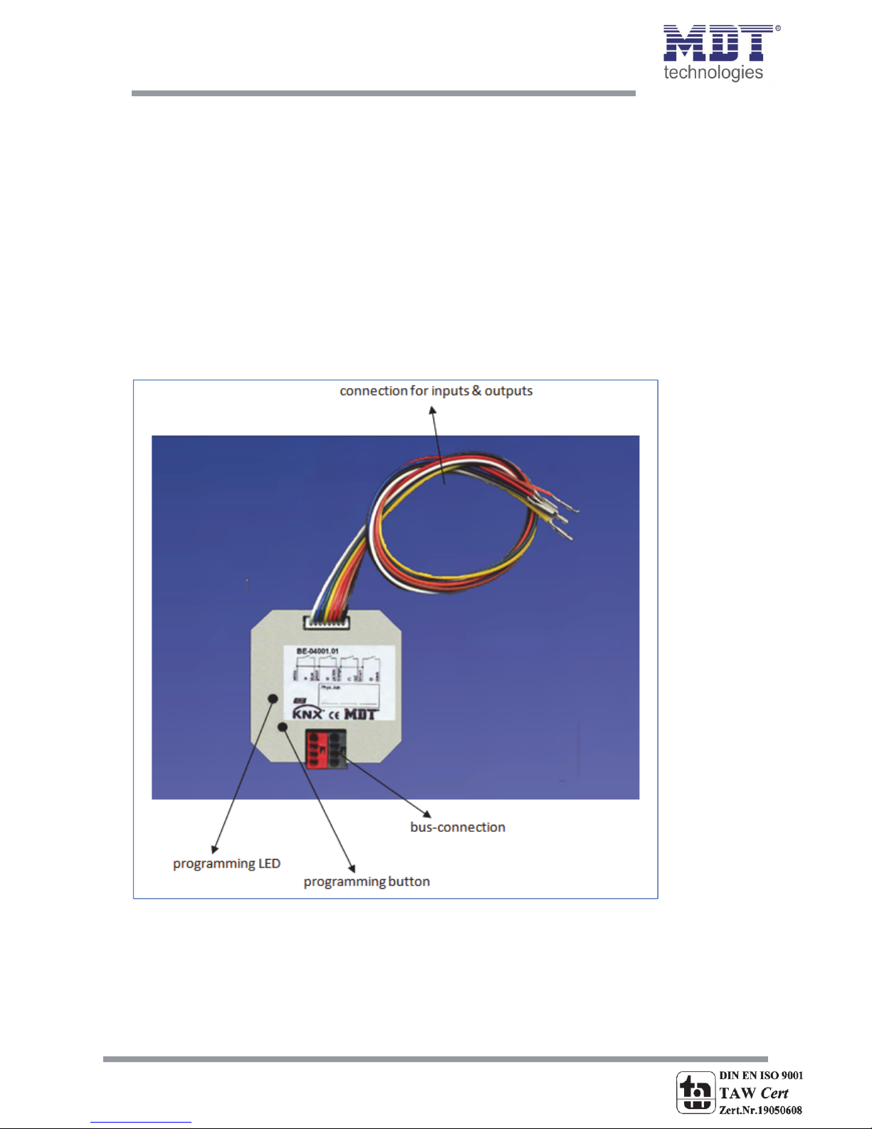
2.4Structure&Handling.....................................................................................................................6
2.5Functions.......................................................................................................................................7
2.5.1Overviewfunctions.................................................................................................................8
2.6SettingsattheETS‐Software.........................................................................................................9
2.7Startingup.....................................................................................................................................9
3Communicationobjects....................................................................................................................10
3.1Communicationobjectsperchannel.........................................................................................10
3.2Communicationobjectslogic......................................................................................................12
3.3Defaultsettingsofthecommunicationobjects..........................................................................13
4ReferenceETS‐Parameter..................................................................................................................14
4.1GeneralSettings..........................................................................................................................14
4.2Configuration...............................................................................................................................16
4.3Identicalparameter.....................................................................................................................17
4.3.1Blockingobject.....................................................................................................................17
4.4ParameterChannelsgrouped......................................................................................................17
4.4.1Dimming...............................................................................................................................18
4.4.2Shutter..................................................................................................................................20
4.4.3Switch...................................................................................................................................21
4.5Parameterschannelsunique.......................................................................................................22
4.5.1Switch...................................................................................................................................22
4.5.2Scene....................................................................................................................................32
4.5.3Counter.................................................................................................................................34
4.5.4Switchshort/long.................................................................................................................36
4.5.5OnebuttonDimming............................................................................................................39
4.5.6One‐buttonShutter..............................................................................................................40
4.5.7LEDOutput...........................................................................................................................41
4.6.Logic............................................................................................................................................42
4.6.1Logicobjecttypeswitch.......................................................................................................44
4.6.2Logicobjecttypescene........................................................................................................46
4.6.3Logicobjecttypebytevalue.................................................................................................46

Technical Manual Universal Interface BE
MDT technologies GmbH • 51766 Engelskirchen • Papiermühle 1
3
5Index...................................................................................................................................................47
5.1Registerofillustrations................................................................................................................47
5.2Listoftables.................................................................................................................................48
6Attachment.........................................................................................................................................49
6.1Statutoryrequirements...............................................................................................................49
6.2Routinedisposal..........................................................................................................................49
6.3Assemblage..................................................................................................................................49
6.44‐BitDimcommand.....................................................................................................................50
6.5Datasheet....................................................................................................................................51

Technical Manual Universal Interface BE
MDT technologies GmbH • 51766 Engelskirchen • Papiermühle 1
4
2Overview
2.1Overviewdevices
Themanualreferstothefollowingdevices,whichareinourassortmentofuniversalinterfaces.
Actuallywecanofferyouthefollowinguniversalinterfaces(OrderCoderespectivelyprintedinbold
type):
BE‐06001.01Input6‐fold
o6Inputs,forfloatingcontacts&LEDs;4Logicblocks;LEDOutputsparameterizeable
BE‐04001.01Input4‐fold
o4Inputs,forfloatingcontacts&LEDs;4Logicblocks;LEDOutputsparameterizeable
BE‐0200.01Input2‐fold
o2Inputs,forfloatingcontacts&LEDs;4Logicblocks;LEDOutputsparameterizeable
2.2Exemplarycircuitdiagrams
Figure1:ExemplarycircuitdiagramBE0400.01‐Modelwith4inputs

Technical Manual Universal Interface BE
MDT technologies GmbH • 51766 Engelskirchen • Papiermühle 1
5
Figure2:ExemplarycircuitdiagramBE0200.01‐Modelwith2inputs

Technical Manual Universal Interface BE
MDT technologies GmbH • 51766 Engelskirchen • Papiermühle 1
6
2.3Usage&areasofuse
Theuniversalinterfacesareaspecialdesignofthebinaryinputs.Theyareusedfortheflush
mountingbehindpush‐buttons.Universalinterfacescontainofthesamefunctionslikethebinary
input,butadditionalofaparameterizeableLEDoutput.ThesingleInputsandoutputspassedoutby
individualconnectioncables.
2.4Structure&Handling
Theuniversalinterfacescontainofindividualconnectioncablesfortheeachinputsandoutputs.The
singleconnectioncablesarecolor‐marked(havealookattheassignmentplanatthenextpage).The
programmingfunctioncanbeactivatedbytheprogrammingbutton.TheprogrammingLEDindicates
thestate,whethertheprogrammingfunctionisswitchedonoroff.
Figure3:OverviewhardwaremoduleUniversalInterface(here:BE‐0400.01forfloatingcontacts,4‐fold)

Technical Manual Universal Interface BE
MDT technologies GmbH • 51766 Engelskirchen • Papiermühle 1
7
Theinputsofthe4‐folduniversalinterfaceareoccupiedinthisway:
InputA: Black&Brown
InputB: Red&Orange
InputC: Yellow&Green
InputD:Blue&White
havealookat2.2Exemplarcircuitdiagram1
Theinputsofthe2‐folduniversalinterfaceareoccupiedinthisway:
InputA: Black&Brown
InputB: Red&Orange
havealookat2.2Exemplarcircuitdiagram2
2.5Functions
Thefunctionalityisidenticalforeverychannel.Thedevicecontainsoftwoorfourchannelsbasedon
thehardwaredesign.
Thedesignationofthechannelsisalwaysinaconsecutivealphabeticorder.
Therearethreepossiblefunctionalitiesforeachchannel:
Disabled
Nofunctionissettothechannelsothatthischanneldoesnotcontainofanycommunicationobjects.
Channelsgrouped
Ifyouselectapairofchannelas“channelsgrouped”,youwillbeabletoparameterizethepairof
channelsasdimming‐function,shutter‐functionorswitching‐function.
Channelsunique
Ifyouselectapairofchannelsas“channelsunique”,youwillbeabletoparameterizeeachchannel
foritselfasswitch,counter,scene,switchshort/long,onebuttondimmingoronebuttonshutter.
Thereareadditional4logicfunctions(and/or)containingofuptotwoadditionalinputobjects.

Technical Manual Universal Interface BE
MDT technologies GmbH • 51766 Engelskirchen • Papiermühle 1
8
2.5.1Overviewfunctions
Generalsettings
Debouncetime10‐120ms,selectableinsteps
Timeforkeystrokelong0,1‐30s,selectableinsteps
Channelsgrouped
Dimmingfunctionbrighter/darkerfunctioncanbeassignedto
thechannelsfreely
Shutterfunctionup/downfunctioncanbeassignedtothe
channelsfreely
Switchingfunctionoff/ontelegramscanbeassignedtothe
channelsfreely
Channelsunique
Switchingfunctionswitchingfunction
togglefunction
statusfunction
timefunctions
oswitchon/offdelay
edgeevaluation
forcedsettings
sendingofbyte‐values
Scenefunctionmemoryfunction
selectionofdifferentscenes
Counterfunctioncountingfunction
edgeevaluation
countingstepscanbechosen
freely
Switchshort/longOn‐/Off‐/togglefunction
short/longindependent
parameterizeable
Onebuttondimmingstepsofdimming
telegramrepetition
Onebuttonshuttershutterfunctionwithonlyone
button
LEDOutputLEDOutputnormal/inverted
permanent‐/flashing‐function
Logicfunctions
AND‐functionswitchingfunction
scenefunction
inverting
OR‐functionswitchingfunction
scenefunction
inverting
Table1:Functionaloverviewuniversalinterfaces

Technical Manual Universal Interface BE
MDT technologies GmbH • 51766 Engelskirchen • Papiermühle 1
9
2.6SettingsattheETS‐Software
Selectionattheproductdatabase:
Manufacturer:MDTTechnologies
Productfamily:BinaryInput
Producttype:UniversalInput
MediumType:TwistedPair(TP)
Productname:addictedtotheusedtype,e.g.:BE‐0400.01Input4‐fold,4TE
Ordernumber:addictedtotheusedtype,e.g.:BE‐0400.01
2.7Startingup
Afterwiringtheallocationofthephysicaladdressandtheparameterizationofeverychannelfollow:
(1) Connecttheinterfacewiththebus,e.g.MDTUSBinterface
(2) setbuspowerup
(3) Presstheprogrammingbuttonatthedevice(redprogrammingLEDlights)
(4) LoadingofthephysicaladdressoutoftheETS‐Softwarebyusingtheinterface(redLEDgoes
out,aswellthisprocesswascompletedsuccessful)
(5) Loadingoftheapplication,withrequestedparameterization
(6) Switchthepowersupplyon
(7) Ifthedeviceisenabledyoucantesttherequestedfunctions(alsopossiblebyusingtheETS‐
Software)

Technical Manual Universal Interface BE
MDT technologies GmbH • 51766 Engelskirchen • Papiermühle 1
10
3C
ommunicationobjects
3.1
C
ommunicationobjectsperchannel
Thecommunicationobjectsappearforeverychannelindependenceoftherespective
parameterization.10numbers(0‐9,10‐19,…)forcommunicationobjectsareautomaticallyassigned
foreverypairofchannels.Thenumerationisconsecutive,sothechannelpairA/Bcanonlyhavethe
numbersfrom0to9,thesameiftheyparameterizedasgroupedchannelsoruniquechannels.With
everyfollowingchannelpairthenumbersoftheobjectsincreaseby10,evenifachannelpairis
disabled.Ifyouchooseachannelpairasunique,thechannel,whichisfirstinthealphabet,will
becomethefirst5numbersandtheotheronewillbecomethefollowingfivenumbers(e.g.channel
A‐‐>0‐4andchannelB‐‐>5‐9).Thenumerationofthechannelsisalwaysthesameevenifsome
channelsaredisabled.
ExceptionsofthisorderarethecommunicationobjectsfortheLED‐outputs.Thesecommunication
objectshavethenumbersbehindthelogicblocks.Alsohere,thefirstnumberafterthelogicblocksis
fortheLEDoutputofchannelA,thesecondfortheLEDoutputofchannelBandsoon.
Thecommunicationobjectsareusedfortheassignmentofthegroupaddresses.
Thefollowingillustrationshowsthecommunicationobjectsforthechannels.Here,channelA/Bare
parameterizedasgroupedwithadual‐surfacedimmingfunction.ChannelsCandDareadjustedas
uniquechannels,sobothchannelshaveanindividualfunction.ChannelCisadjustedasswitchand
channelBasLEDoutput:
Figure4:Communicationobjectsperchannel

Technical Manual Universal Interface BE
MDT technologies GmbH • 51766 Engelskirchen • Papiermühle 1
11
Ifachannelpairisselectedasdisabled,noobjectswillbeshown.Sotherearenoopportunitiesfor
programmingthischannel.
Thesearetheavailableobjectsforeachchannel:
Nr.FunctionUsageDatatype
0SwitchedgecontrolDPT1.001Out,Read
0Sendforcedsettingforcecontrol/switchDPT2.001Out,Read
0Shuttersdown/updrivingofshuttersDPT1.008Out,Read
0Dimmingon/offtogglingofthedimminglightsDPT1.001Out,Read
0Switchon/offtwobuttonswitchingDPT1.001Out,Read
0ResetcounterresetthecountervalueDPT1.001In,Write
0SendvaluesendstheparameterizedvalueDPT5.001Out,Read
0push‐buttonshortsendsactionforshortkeystrokeDPT1.001Out,Read
1ValuefortoggleedgecontrolwithtogglefunctionDPT1.001In,Write
1Stop/Blindsopen/closedrivingoftheblinds/stopping
movementoftheshutters
DPT1.009Out,Read
1DimmingdimmingDPT3.007Out,Read
2ScenescenecontrolDPT18.001Out,Read
2Valueforchangeof
direction
reversalofdirectionforshuttersDPT1.001Out,Read
2push‐buttonlongsendsactionforlongkeystrokeDPT1.001Out,Read
3CountercountingDPT12.001Out,Read
4BlockingobjectblockstherelatedchannelDPT1.001In,Write
+5nextchannel
22/32LEDswitchAturnLEDDPT1.001Out,Read
+1nextLEDoutput
Table2:Communicationobjectsperchannel

Technical Manual Universal Interface BE
MDT technologies GmbH • 51766 Engelskirchen • Papiermühle 1
12
3.2Communicationobjectslogic
Therearecommunicationobjectsforthelogicfunctionateveryuniversalinterfaceadditionaltothe
communicationobjectsperchannel.Theseobjectscanbeparameterizedandshownindependent
fromtheparameterizationofthechannels.Thelogicobjectshavethenumbersfrom20ata4‐fold
universalinterfaceandthenumbersfrom10ata2‐folduniversalinterface.Thefirstlogicblockgets
assignedthefirstthreenumbers,soata2‐foldinputfrom10to12andata4‐foldinputfrom20to
22.Everyfollowingblockincreasesthenumbersby3.
Theaddressingcanbemadebyusingthecommunicationobjectsforthelogicanalogoustothe
addressingbythechannels.
Thefollowingcommunicationobjectsforthelogiccanbeshown:
Figure5:communicationobjectslogic
Ifalogicblockisdisabled,therewillnocommunicationobjectsbeshown.Thereforenoaddressingis
possible.Everybinaryinputcontainsof4logicblocksforwhichthefollowingobjectscanbeshown:
Nr.FunctionUsageDatatype
10/20Logicinput1ALogicinputDPT1.001In,Write
11/21Logicinput1BLogicinputDPT1.001In,Write
12/22Logicoutput1LogicoutputDPT1.001Out,Read
12/22Logicoutput1sceneLogicoutputsceneDPT18.001Out,Read
+3nextlogicblock
Table3:communicationobjectslogic

Technical Manual Universal Interface BE
MDT technologies GmbH • 51766 Engelskirchen • Papiermühle 1
13
3.3Defaultsettingsofthecommunicationobjects
Thefollowingchartshowsthedefaultsettingsforthecommunicationobjects:
Defaultsettin
g
s
Nr.Channel/Input FunctionLength PriorityCRW T U
0InputASwitch1Bit Low XXX
0InputAShutter1Bit Low XXX
0InputASendvalue 1Byte Low XXX
0InputASendforcedsetting 2Bit Low XXX
0InputAResetcounter 1Bit Low X X X
0InputADimmingon/off 1Bit Low XXX
0InputApush‐buttonshort 1Bit Low XXX
0InputApush‐buttonshort 1Byte Low XXX
0InputA/BSwitchon/off 1Bit Low XXX
0InputA/BDimmingon/off 1Bit Low XXX
0InputA/BShutterdown/up 1Bit Low XXX
1InputAValuefortoggle 1Bit Low XXX
1InputAStop/Blindsopen/close 1Bit Low XXX
1InputADimming4Bit Low XXX
1InputA/BDimming4Bit Low XXX
1InputA/BStop/Blindsopen/close 1Bit Low XXX
2InputAScene1Byte Low XXX
2InputAValueforchangeofdirection 1Bit Low X X X X
2InputAValuefortoggle 1Bit Low X X X X
2InputAPush‐buttonlong 1Bit Low XXX
3InputACounter4Byte Low XXX
4InputABlockingobject 1Bit Low X X X
+5nextinput
80/40Logicinput1ALogicinput1A 1Bit Low X X X
81/41Logicinput1BLogicinput1B 1Bit Low X X X
82/42Logicoutput1Logicoutput1 1Bit Low XXX
82/42Logicoutput1
scene
Logicoutput1scene1ByteLowXX X
+3nextlogicblock
22/32LEDchannelALEDswitch 1Bit Low XXX X X
Table4:Communicationobjects–defaultsettings
Youcanseethedefaultvaluesforthecommunicationobjectsfromtheupperchart.Accordingto
requirementsthepriorityoftheparticularcommunicationobjectsaswellastheflagscanbe
adjustedbytheuser.Theflagsallocatesthefunctionoftheobjectsintheprogrammingthereby
standsCforcommunication,RforRead,Wforwrite,TfortransmitandUforupdate.

Technical Manual Universal Interface BE
MDT technologies GmbH • 51766 Engelskirchen • Papiermühle 1
14
4ReferenceETS‐Parameter
4.1GeneralSettings
Thefollowingparametersexistonceandaffectallchannels:
Figure6:Generalsettings
Thefollowingchartshowsthedynamicrangeforthegeneralsettings:
ETS‐textDynamicrange
[defaultvalue]
comment
Debouncetime10..120ms
[10]
Theinputsaredebouncedwiththis
time
Timeforkeystrokelong0,1‐30sec
[0.8sec]
releasesthetimewhentheETS
recognizesalongkeystroke
BehavioratbuspowerupNoreadvaluefortoggle
Readvaluefortoggle
activatesthereadingofthevaluefor
toggleatbuspowerup
Table5:Generalsettings

Technical Manual Universal Interface BE
MDT technologies GmbH • 51766 Engelskirchen • Papiermühle 1
15
1. Thesettingoptionforthedebouncetimeisfordebouncingoftheinputsignalsfrom
mechanicalswitches
2. Theparameter“Timeforkeystrokelong”allocatesastaticvaluetotheuniversalinterface
fromwhenalongkeystrokeisrecognized.Thisparameterisimportantforfunctions,which
havedifferentfunctionsforalongandashortkeystroke.
3. Theparameter“Behavioratbuspowerup”definesthebehavioroftheuniversalinterface
atabuspowerreturn.Thesetting“Readvaluefortoggle”effectsthatallcommunication
objects“valuefortoggle”areread.SotheInputknowsthecurrentstatusoftheobjects.If
youchoosethesetting“noreadvaluefortoggle”,theinputwillnotknowthecurrent
statusoftheactor.Sotheinputassumesanunconfirmedvaluefortheobjects“valuefor
toggle”andsendsalwaysa“0”‐signalatthenextoperation.Onlynowtheinputknowsthe
statusoftheactorandcansendtherightvalues.Butifyouchoosethereadofthese
valuesatabuspowerup,theinputwillsendimmediatelytherightvaluefortoggling.

Technical Manual Universal Interface BE
MDT technologies GmbH • 51766 Engelskirchen • Papiermühle 1
16
4.2Configuration
Settingofthefunctionalityofthechannels:
Figure7:Usageofthechannels
ETS‐textDynamicrange
[defaultvalue]
comment
FunctionInputA/B–[O/P]disabled
Channelsgrouped
Channelsunique
Operatingmodeofthe
channels
Table6:Parameterchannel‐configuration
Thereare3differentoperatingmodesforeverychannel(havealookatchart6).Thefollowigoptions
toparameterizethechannelsaredependenttothechoosenoperatingmode.Ifyoudisablethe
channel,therewillbenooptionstoparameterizethischannel.

Technical Manual Universal Interface BE
MDT technologies GmbH • 51766 Engelskirchen • Papiermühle 1
17
4.3Identicalparameter
4.3.1Blockingobject
Aswellforgroupedchannelsasforuniquechannelstheblockingobjectcanbeactivated.Atthe
uniquechannelsoneblockingobjectforeverychannelcanbeactivated.Forgroupedchannels,you
canactivateoneblockingobjectforbothchannels.Thecommunicationobjectforachannelappears
assoonasitisactivatedforachannel.Ata4‐folduniversalinterface,therearesoupto4blocking
objectsparameterizeable.Thecorrespondingchanneloftheblockingobjectisblockedbysendinga
logical1.Ablockedchannelisnotcontrollableaslongasitisblocked.Bysendingalogical0,the
channelcanbeunblockedagain.
NumberNameLength Usage
4Blockingobject1Bitblockstherelatedchannelbysendingalogical1
Table7:Communicationobjectblockingobject
4.4ParameterChannelsgrouped
Thechartshowsthesettingoptionsforgroupedchannels:
ETS‐textDynamicrange
[defaultvalue]
comment
InputA/BDimming
Shutter
Switch
Operatingmodeofthechannel
DimmingfunctionA/BBrighter/Darker
Darker/Brighter
Defineswhichchannelshould
dimupandwhichshoulddim
down
ShutterfunctionA/BUp/Down
Down/Up
Defineswhichchannelshould
drivetheshutteradownand
whichup
SwitchfunctionA/BOn/Off
Off/On
Defineswhichchannelshould
switchoffandwhichon
BlockingObjectInactive
Active
Theblockingobjectcanbe
displayedforeverypairof
channels
Table8:ParameterChannelsgrouped
Bychoosingchannelsasgrouped,twochannelsbecomeonecommonfunction.Thegrouped
functioniscalleddualsurface,dualsurfacedimming,anddualsurfaceshutter.Incontrasttothe
singlesurfacefunctions,oneactioncanbeperformedindependentformtheotherone.Oneinput
performsalwaysonefunction.Theassignmentfortheinputscanbemadeindividually,soitis
possibletoconfigurewhichinputshouldforexampledrivetheshuttersupandwhichdown.

Technical Manual Universal Interface BE
MDT technologies GmbH • 51766 Engelskirchen • Papiermühle 1
18
4.4.1Dimming
Thetwo‐buttondimmingfunction(channelsgrouped)isforcontrollingdimmingactuatorsbystart‐
stopdimmingcommands.
Thefollowingparametersarevisible,whenapairofchannelsischosenasdimming‐function:
Figure8:Parametertwo‐buttondimming
NumberNameLength Usage
0Dimmingon/off1BitSwitchingfunctionofthedimmingprocess;
actionforashortkeystroke
1Dimming4BitDimmingfunction;actionforalongkeystroke
Table9:Communicationobjectstwo‐buttondimming
Whenapairofchannelsisparameterizedasdimmingfunction,twoobjectsareshown.Oneobject
reactstoashortkeystroke,theswitchingobject“Dimmingon/off”,andtheotherobjectreactstoa
longkeystroke,thedimmingobject“dimming”.
Itispossibletoparameterizethisfunctionasbrighter/darkerorasdarker/brighter.Thefirstfunction
belongsalwaystothefirstinput.Ifyouswitchthisparameter,thefunctionwillbeswitched
automatically.
Bychoosingthedimmingfunction(channelA/B)asbrighter/darker,thefunctionreactsinthisway:
AshortkeystrokeatinputAswitchesthelightson.Thelightsareswitchedoffbyashortkeystrokeat
inputB.Alongkeystrokedimsthelightsstepbystepuntilreleasingthelongkeystroke.Thelightsare
dimmedbrighteratinputAanddarkeratinputB.Theuniversalinterfacestartsalwayswiththelast
brightnesslevel,beforeswitchingoff.
Thestepsizeissetfixedto100%atthedualsurfacedimming.Itisastart‐stopdimming.thatmeans
thelightsaredimmedaslongasyouholdthebutton.Afterreleasingthebuttonastopvalueissent,
whichstopsthedimmingprocess.Soyoucandimthelightswithonlyonekeystrokefrom0%to
100%orfrom100%to0%,bypushingthebuttonlongenough.

Technical Manual Universal Interface BE
MDT technologies GmbH • 51766 Engelskirchen • Papiermühle 1
19
Thechartshowsthecorrelationsbetweenthedimming‐andtheswitching‐object:
Table10:Dimmingfunction
Thefollowingdiagramshowsthedualsurfacedimmingfunction:
FunctionBrighter/DarkerFunctionDarker/Brighter
InputInputAInputBInputAInputB
DimmingfunctionBrighterDarkerDarkerBrighter
SwitchingfunctionOnOffOffOn

Technical Manual Universal Interface BE
MDT technologies GmbH • 51766 Engelskirchen • Papiermühle 1
20
4.4.2Shutter
Thetwo‐buttonshutter‐functiontriggersshutteractuators,whichcandriveshutterandblinds.
Thefollowingparametersareshown,whenapairofchannelisadjustedasshutterfunction:
Figure9:Two‐buttonshutterfunction
NumberNameLength Usage
0ShutterDown/Up1BitDrivingfunctionfortheshutters,actionfora
longkeystroke
1Stop/BlindsOpen/Close1BitStop/Adjustmentoftheblinds,actionfora
shortkeystroke
Table11:Communicationobjectstwo‐buttonshutterfunction
Ifyouchooseapairofchannelsasshutterfunction,twocommunicationobjectswillappearforthis
pairofchannel.Ontheonehandthestop/blindadjustmentobjectcalled“Stop/BlindsOpen/Close”,
whichrespondstoashortkeystrokeandontheotherhandtheDrivingobjectcalled“Shutter
Down/Up”,whichrespondstoalongkeystroke.
Thedrivingobjectisformovingtheshuttersupanddown.Thestop‐/blindadjustmentobjectisfor
theadjustmentoftheblindsandadditionalitstopsarunningmovementoftheshutter.
Everyshutteractuatorcontrolswitha0‐signaltheup‐movementandwitha1‐signalthedown
movement.Sotheuniversalinterfacesendsthesesignalstothecorrespondingdrivingcommands.
Fromhardwareversion2.6(havealookattheprintofthesideofthedevice:RX.X),itisadditional
possibletoswitchthefunctionsforalongandashortkeystroke.Soitcanbechosenwhetherhe
shutter/blindsshallbedrivenviaalongorashortkeystroke.TheStop‐/Blindadjustmentobjectis
adjustedbytheotheroperatingconcept.
TheChartshowsthecorrelationsbetweentheStop‐/Blindadjustmentobjectandthedrivingobject
fortheindividualchannels:
Table12:Shutterfunction
FunctionDown/UpFunctionUp/Down
InputInputAInputBInputAInputB
Stop‐/Blind
adjustmentobject
DownUpUpDown
DrivingobjectStop/closeblindsStop/openblindsStop/openblindsStop/closeblinds
This manual suits for next models
2
Table of contents