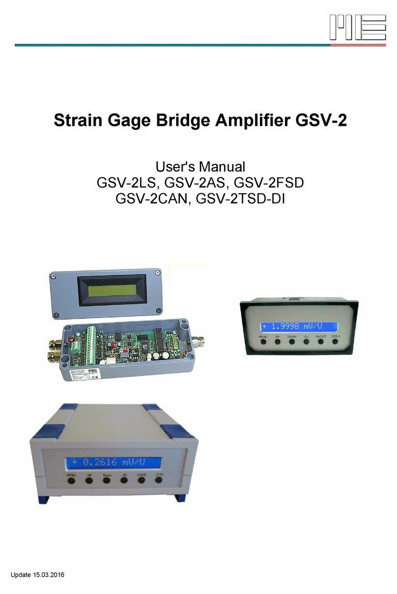
ME-Messysteme GSV-2 Series User manual

Strain Gage Bridge Amplifier GSV-2
User's Manual
GSV-2LS, GSV-2AS, GSV-2FSD
GSV-2CAN, GSV-2 SD-DI
Updated 14.11.2017
ME-Meßsysteme GmbH
16761 Hennigsdorf Fax: +49 3302 89824 69 Web: www.me-systeme.de


Table of Contents
Description..........................................................................................................................................5
Pin Configuration....................................................................................................................................6
15 pole terminal block for the sensor connection.......................................................................6
5 pole terminal block for RS232 / RS422.......................................................................................7
Backplate of the table case (GSV-2 SD-DI)..................................................................................7
Side panel GSV-2 SD-DI...................................................................................................................8
12-pole terminal block GSV-2 SD...................................................................................................8
Connection scheme 12-pole terminal block.................................................................................9
15-pole SUB-D connector of the GSV-2 SD (-DI).........................................................................9
Connection diagram 15-pole SUB-D connector.........................................................................10
Connection and start-up.....................................................................................................................10
Charging the integrated battery....................................................................................................10
Connecting the sensor...................................................................................................................10
Connecting the serial interface.....................................................................................................11
Commissioning devices with CANopen interface.....................................................................12
3 pole connector plug / socket M8..........................................................................................12
Jumper for terminating resistor 120 Ohm.............................................................................12
Setting the input sensitivity............................................................................................................12
Null-balance calibration..................................................................................................................13
Using switching output...................................................................................................................14
Usage of the keyboard and the menu..........................................................................................14
Advice................................................................................................................................................16
Description of the keys...................................................................................................................16
Number format................................................................................................................................17
Settings of the measuring value display (scaling factor).........................................................17
RS 232/422 Protocol of the GSV-2 Strain Gage Bridge Amplifier GSV-2 ...................................17
Data output.......................................................................................................................................17
Display settings................................................................................................................................18
Output of the register data ............................................................................................................19
Commands to the GSV-2...............................................................................................................19
able of commands........................................................................................................................20
Description of the commands.......................................................................................................23
CANbus / CANOpen protocol of the GSV-2-CANOpen..................................................................56
Connecting the CAN-Bus wires.....................................................................................................56
Bus-termination...............................................................................................................................57
Supported services.........................................................................................................................57
Interpretation of the 1st x-PDO...................................................................................................57
Send-conditions for the 1st x-PDO.............................................................................................58
Default settings:...............................................................................................................................58
General advices and ips ...................................................................................................................59
echnical Data......................................................................................................................................60
CANbus Interface............................................................................................................................61
CANOpen Vendor-ID........................................................................................................................61
ME-Meßsysteme GmbH
16761 Hennigsdorf Fax: +49 3302 89824 69 Web: www.me-systeme.de 3

Resolution.........................................................................................................................................62
Description of the jumpers / selectors........................................................................................64
Dimensions of the circuit board GSV-2L....................................................................................64
Dimensions of the aluminium housing of the GSV-2AS...........................................................65
Front panel cut out and housing of the GSV-2FSD....................................................................66
Dimensions of the GSV-2 SD-DI..................................................................................................66
Changelog.........................................................................................................................................66
ME-Meßsysteme GmbH
4 16761 Hennigsdorf Fax: +49 3302 89824 69 Web: www.me-systeme.de

Description
he GSV-2 is a strain gauge measuring amplifier with a serial output signal. Depending on
the type, the following interfaces are available: RS232, RS422, USB, CANbus / CANopen,
Ethernet.
he measuring amplifier GSV-2 is available in different housing models and equipment
variants:
•GSV-2 SD-DI: Desktop housing with display, USB, RS232, and integrated,
rechargeable battery
•GSV-2AS, GSV-2ASD: Aluminum housing with RS232, RS422, CANbus, display
•GSV-2FSD-DI: front panel mounting with display, RS232, RS422, CANbus
•he model GSV-2MSD-DI with display, USB, integrated rechargeable battery and SD
memory card (data logger function) is especially suitable for mobile use.
he compact dimensions of the GSV-2 SD-DI and the GSV-2MSD-DI fit into any briefcase.
With the built-in rechargeable battery 14.8V, 2.8Ah with this model, an operating time of at
least 8 hours is possible.
Straingage sensors can be connected either via screw terminals or a 15-pin Sub-D
connector.
he keyboard can be used to recall presettings of up to 6 sensors. In addition to the menu-
driven adjustment of sensor data, the GSV-2 SD-DI and GSV-2MSD-DI allow you to
configure the display for strain gage stress analysis.
he setting of the display during stress analysis with strain gages is menu-driven.
Straingage quarter bridges, half bridges and full bridges can be connected. he amplifier
has built-in bridge complements for 120 ohms, 350 ohms and 1000 ohm strain gauges.
ME-Meßsysteme GmbH
16761 Hennigsdorf Fax: +49 3302 89824 69 Web: www.me-systeme.de 5

Pin Configuration
15 pole terminal block for the sensor connection
Figure 1: Terminal block 15pole and 5 pole in GSV-2LS, GSV-2AS, GSV-2ASD and GSV-2FSD
Pin Name Description ip
1 GNDBSupply ground Connection for cable shield
2 +Us Positive bridge sensor supply
3 +UFPositive sens for 6-wire technology
4 +UDPositive differential input
5 -UDNegative differential input
6 -UFNegative sens for 6-wire technology
7 -Us Negative bridge sensor supply
he signals at terminals 2..7 are
recorded by software in channel 0.
Connection of sensors in 4- or 6-wire
technology.
Bridging between +Us and +UF as
well as between -US and -UF are not
necessary.
8 UEAnalogue Input 0..10V
9 UAAnalogue Output ±5 V / option. 4...20mA
10 GNDAGround analogue In/Output
Analog input between UE and GNDA.
he signals between UE and GNDA
are recorded by software in channel
1. Analog output between UA and
GNDA
11 SW1 ² hreshold output No. 1 Open Collector (Open Emitter alternatively),
galvanically isolated
12 ara1are input Affects digital serial and analogue output
13 SW2 2hreshold output No. 2 See ip for SW1
14 UBSupply voltage 12..24 VDC
15 GNDBSupply ground
Connection for supply voltage
able 1: 15pole terminal block in GSV-2LS, GSV-2AS, GSV-2ASD and GSV-2FSD
1 In case of voltages above 3.4 V at this terminal, a tare adjustment is initiated. Offset adjustment is then done in the analog part of the
GSV. In addition the digital output is also set to zero.
2 hreshold values are programmed via the RS 232 port.
ME-Meßsysteme GmbH
6 16761 Hennigsdorf Fax: +49 3302 89824 69 Web: www.me-systeme.de

5 pole terminal block for RS232 / RS422
Pin Standard CAN/CANopen Description
A GNDCGNDCGround RS232 / RS422 Interface
B RX / RX- Rx Data connection Rx for RS232 / Rx- for RS422
C X / X- x Data connection x for RS232 / x- for RS422
D RX+ CAN_GND Rx+ for RS422 Ground CAN bus
E X+ CAN_L x+ for RS422 CAN low
F n.a. CAN_H n.c. CAN high
Backplate of the table case GSV-2TSD-DI)
Figure 2: Backpla e GSV-2TSD (-DI)
M8 plug connector for GSV-2TSD-DI CANopen
In the version with CANopen Interface there are two additional M8 male / female
connectors on the backplate.
Pin Funktion Wire colour
1 CAN-H brown
3 CAN-L blue
4 GND black
the CAN-Interface is galvanically isolate .
ME-Meßsysteme GmbH
16761 Hennigsdorf Fax: +49 3302 89824 69 Web: www.me-systeme.de 7

Side panel GSV-2TSD-DI
Five 2mm plugs are arranged at the side panel. wo isolated threshold outputs and one
input for the tare / set zero functioa are available.
black Set zero input Input voltage 9 .. 30 Volts
green hreshold 1 CMOS relay outputs,
isolate , 60 VDC, 40 VAC
yellow hreshold 2 CMOS relay outputs,
isolate , 60 VDC, 40 VAC
12-pole terminal block GSV-2TSD
Pin Name Description ip
1 Shielding Shield and GNDBConnect the cable shield here
2 +Us Positive bridge sensor supply
3 +UFPositive sens for 6-wire technology
4 +UDPositive differential input
5 -UDNegative differential input
6 -UFNegative sens for 6-wire technology
7 -Us Negative bridge sensor supply (GND)
he signals at terminals 2..7 are
acquired by software. Connection of
sensors in 4- or 6-wire technology.
Bridging between +Us and +UF as well
as between -US and -UF are not
necessary.
8 -UD2 Negative differential input 2
9 HB Completion for halfbridge
o connect half- and quarterbridges, terminal 8
and 9 must be connected together. See
connection scheme on p.5.
10 QB120 Completion quarterbridge 120 Ohms
11 QB350 Completion quarterbridge 350 Ohms
12 QB1000 Completion quarterbridge 1000 Ohms
For connection of quarterbridge, 120,
350 or 1000 Ohms.
able 2: Connection of 12-pole terminal block GSV-2 SD (-DI)
ME-Meßsysteme GmbH
8 16761 Hennigsdorf Fax: +49 3302 89824 69 Web: www.me-systeme.de

Connection scheme 12-pole terminal block
Figure 3: Connec ion of Full-, Half- and Quar erbridge sensors o he 12-pole erminal block
15-pole SUB-D connector of the GSV-2TSD -DI)
Pin Name Description
1 Shielding Cable shield
2 GNDAAnalogue input ground
7 are are input / rigger input
9 UEAnalogue input
10 UAAnalogue output
6 +Us Positive bridge sensor supply
5 -Us Negative bridge sensor supply
8 +UDPositive differential input
15 -UDNegative differential input
13 +UFPositive sens for 6-wire technology
12 -UFNegative sens for 6-wire technology
14 HB Completion for halfbridge
11 QB120 Completion quarterbridge 120 Ohms
3 QB350 Completion quarterbridge 350 Ohms
4 QB1000 Completion quarterbridge 1000 Ohms
o connect half- and
quarterbridges, pin 14
and pin 15 must be
connected together.
Quarterbridges are
connected in 3-wire
technology at pins 5, 8
and QB (3, 11 or 4).
able 4: Connection of SUB-D 15 plug
ME-Meßsysteme GmbH
16761 Hennigsdorf Fax: +49 3302 89824 69 Web: www.me-systeme.de 9

Connection diagram 15-pole SUB-D connector
Table 5: Connec ion of Full-, Half- and Quar erbridge sensors o he 15-pole SUB-D connec or
All ground connections are individually protected by interference suppressor inductors in the GSV. erminals
GNDB are connected to the housing via interference suppression inductor. Currents above 1A between the
terminals and the housing result in damage to the interference suppression inductor. Before connecting,
please check whether housing, supply ground, the ground of your data acquisition system and your port are at
the same potential.
Connection and start-up
Charging the integrated battery
he integrated rechargeable battery of the GSV-2 SD-DI is charged via the DC socket 2.1 x
5.5 mm at the back of the device. he state of charge is indicated by the LED on the back of
the device. When the battery is fully charged, the LED goes out or the brightness is reduced.
he charging time is about 8 ... 12 hours.
Connecting the sensor
A strain gage full bridge or a load cell is connected to the amplifier's terminal block as
shown below:
4- Wire technology 6-Wire technology1):
Sensor supply + PIN 2 Sensor supply + PIN 2
Sensor supply - PIN 7 Sensor supply - PIN 7
Sensor signal + PIN 4 Sensor signal + PIN 4
Sensor signal - PIN 5 Sensor signal - PIN 5
Sense wire + PIN 3
ME-Meßsysteme GmbH
10 16761 Hennigsdorf Fax: +49 3302 89824 69 Web: www.me-systeme.de

Sense wire - PIN 6
All cable shields should be connected to the metal of the cable entrance or to GND.
he supply voltage must be connected to the PINs 14 (+) and 15 (GND) of the GSV-2LS,
GSV-2AS, GSV-2ASD and the GSV-2FSD
he analogue output transmits a signal which is proportional to the measured force. We
offer the GSV-2 with the following options: ±5 V, 0...10 V, or 4...20 mA current output. he
output signal is present at the PINs 9 and10 (Ground).
he sensitivity of the amplifier can be changed by removing the Jumper „JP1“ from 2 mV/V)
to 1 mV/V. he jumper „JP1“ is located on the circuit board, For more detailed information
have a look at page 64.
Connecting the PINs 12 and 13 triggers a zero-point adjustment at the analog and digital
outputs. he analog output delivers a voltage from 0 V or a current of 4mA. he system is
then ready for measurements.
1) At the analog output the benefits of the 6-conductor technology are not supported.
Connecting the serial interface
If an RS 232 or RS422 port is used, the following connections should be set up to the PC:
GSV-PIN Cable type 9-pol. Sub-D-Pin (PC-side)
A GND Interface ground GND 5
B RX(-) Data wire X 3
C X(-) Data wire RX 2
D (RS 422 only) TX+ Data wire TX+
E (RS 422 only) RX+ Data wire RX+
he data cables RX and X between the amplifier and the PC are crossed at the SUB-D
connector of the GSV-2 SD.
he measuring values will be displayed on the PC while starting the supplied configuration
programm.
he measuring amplifier GSV-2 SD-DI needs a fully-connected null modem cable, which
means crossing of RxD with xD, R S with C S, and DCD+DSR with D R also GND with
ME-Meßsysteme GmbH
16761 Hennigsdorf Fax: +49 3302 89824 69 Web: www.me-systeme.de 11

GND (2 with 3, 7 with 8, 1+6 with 4 as well as 5 with 5).
Commissioning devices with CANopen interface
For devices with CANopen interface the changing of settings via USB port or via RS232
interface is blocked. hese settings via USB or RS232 will be however possible only with the
switch off of the CANopen interface.
o ensure the sonformity with the CANopen protocol, the CANopen interface must be
switched on in the factory state.
he switch off of the CANopen interface is possible with the program “GSV- erm”.
You can find the corresponding point to switch-off the CANbus under this path: "2" (for the
second side) --> "b" (for baud rate / CAN) --> "c" (for CANbus) --> "1" (for switch on/off).
Please note the instructions ba-GSV2CanOpen.pdf.
3 pole connector plug / socket M8
Connector plug and socket are 1:1 connected.
Pin Funktion GSV-3CAN Wire colour
1 ransmit Data xD / CAN_H 13 brown
3 Receive Date RxD / CAN_L 12 blue
4 GND 11 black
Jumper for terminating resistor 120 Ohm
he fotos show the position for the jumper. For closed jumper the terminating resistor of
120 Ohm is activated.
Jumper for terminating resistor at GSV-2AS Jumper for terminating resistor at GSV-2 SD-DI
Setting the input sensitivity
In the default configuration, the measurement amplifier's input sensitivity is ±2 mV/V.
At this input sensitivity the measurement amplifier works with a bridge excitation voltage of
2.5V.
ME-Meßsysteme GmbH
12 16761 Hennigsdorf Fax: +49 3302 89824 69 Web: www.me-systeme.de
1
4
3

For specific applications it may be necessary to adjust the measurement amplifier's input
sensitivity.
a) Enlargement of the input sensitivity and thus the measurement range to 3-5 mV/V,
e.g. for using sensors with an output signal of 3.0 mV/V (mV output voltage per volt bridge
excitation voltage).
b) Reduction of the input sensitivity to 1 mV/V with a bridge excitation voltage of 5.0 V,
e.g. if an especially high resolution is to be achieved.
a) he enlargement of the measurement range from 2.0 mV/V to 3.5 mV/V can be
performed with the help of the gsvterm.exe configuration software. Further information is
to be found in ba-gsvterm.pdf, the instruction manual.
b) he bridge excitation voltage can be converted from 2.5V to 5.0V by relocating a
jumper. Jumper JP1 must be relocated in position 1 for 5.0 V (page 13, GSV-2 circuit board).
he input sensitivity is reduced to 1 mV/V with this mesure. Jumper JP1 is located in
position 2 in the original delivery status.
Please note: after a change in the bridge excitaion voltage, an automatic calibration must
be triggered with the GSVControl software. Further instructions are to be found in ba-
gsvcontrol.pdf, the instruction manual for the software.
A sensor with a specific value of 1 mV/V supplies an anlogue output signal of 5 V or 10 V. or
20 mA in position 1 at nominal load, depending on the option ordered.
A sensor with a specific value of 2 mV/V then supplies 100% of the output signal at half the
nominal load.
Null-balance calibration
he amplifier's calibration range is ±120% of the measurement range which means that
unsymmetric measuring bridges can also be calibrated.
he GSV-2's operating system performs a null-balance calibration if a level of over 3.4 V
is present at input relative to GND. It is permissible to connect input with the
operating voltage of 12V or 24V to perform a null-balance calibration. his voltage must be
present for at least 8 ms to trigger the calibration.
A voltage level at input triggers a combination of an offset calibration and a compensation
of the digital output value to 0 in devices with a serial interface. he offset
calibration can be triggered and the output value set to 0 separately via the serial interface.
he null-balance calibration lasts approx. 0.12 s for devices with a 250 Hz analogue filter
and a set transmission rate f of 10Hz.
During the calibration, there is no valid signal at the analogue output. Serial data
transmission and control of the thresholds is deactivated for the duration of the calibration.
ME-Meßsysteme GmbH
16761 Hennigsdorf Fax: +49 3302 89824 69 Web: www.me-systeme.de 13

Please note: if the so-called Logger Mode is activated via the configuration software, no
null-balance calibration is performed with a high level at input . A measurement value is
sent via the serial interface instead.
Using switching output
he GSV-2 has two opto-decoupled, digital outputs (terminals 11 and 13).
In the standard version, these outputs are configured as OpenCollector outputs.
he coil of a relay can be switched between output SW1 or SW2 and supply voltage UB.
he relay is activated if the threshold is exceeded. he level at SW1 or SW2 then changes
from High to Low.
By changing resistances on the circuit board, SW1 and SW2 can also be used as
OpenEmitter outputs. he logic is inverted compared to configuration with an
OpenCollector output.
he switching thresholds are calibrated via the serial interface.
he switching outputs can be configured via software either as a threshold switch or as a
window comparer.
he hysteresis of the threshold switch can be adjusted by assigning the switch-on and
switch-off thresholds their own values.
he switch-on threshold must be assigned a larger value than the switch-off threshold.
Usage of the keyboard and the menu
Menu entry level 1 Menu entry level 2 Menu entry level 3
Sensor config. ➔unit
➔Sensor capacity
➔Rated output
Select the unit1
Setting the physical nominal value of the
sensor.2
Setting the electrical rated output of the sensor.²
Strain analysis ➔Set gage factor
➔Set bridge type
➔Setting the gage factor between 0,2 and 2583
➔Full bridge: Full bridge circuit with 4 single
1 Changing the unit doesn't change the measuring value's scaling!
2 Changing the sensor capacity or the rated output changes the measuring value's scaling.
3 Changing the starin gauge parameters of the strain analysis changes the measuring value's scaling and the
unit.
ME-Meßsysteme GmbH
14 16761 Hennigsdorf Fax: +49 3302 89824 69 Web: www.me-systeme.de

Menu entry level 1 Menu entry level 2 Menu entry level 3
strain gauges, all in longitudinal direction.³
➔Half bridge: Half bridge circuit with 2 single
strain gauges, both in longitudinal direction.³
➔Quarter bridge: Quarter bridge circuit with one
single starin gauge.³
➔PR.full bridge: Full bridge circuit with 4 single
strain gauges, 2 in longitudinal and 2 in lateral
direction.³
➔PR.half bridge: Half bridge circuit with 2 single
strain gauges, 1 in longitudinal and 1 in lateral
direction ³
Menu entry level 4
Set Poissons ratio (only if PRfull or PR.half bridge
was selected in level 3). Number value from 0 to
0,5.³
Load settings ➔Default: Factory
settings, i.e. restoring the
GSV-2 parameters of the
initial delivery state.
➔User 1: User
configurable parameter
record No.1, i.e. loading
values that were
previously saved in “User
1” with Save settings.
➔...and so on, to
➔User 6 like 1, but record
No 6
Save settings Storing the actual parameter
configuration in User 1 to
User 6
Scaling Number value between 0,15
and1580000
Data acquisition ➔Data frequency
➔Data period
Number value for measuring values per second
[Hz]
Number value for data period in seconds
ME-Meßsysteme GmbH
16761 Hennigsdorf Fax: +49 3302 89824 69 Web: www.me-systeme.de 15

Menu entry level 1 Menu entry level 2 Menu entry level 3
Options ➔Set channel
➔Set threshold
➔Offset value
➔Language²
➔CAN settings2
Number value 0 or 1
➔on-threshol 1 / 2 Number value of the on-
threshol No. 1 or 2
➔off-threshol 1 / 2 Number value of the off-
threshol No. 1 or 2
➔ Number value that will be a e to every
measuring value
➔German or English
➔CAN No e-ID
➔CAN-Bau rate
➔CAN on/off
–By pressing the Menu-key the upper menu level will be re-entered.
–By pressing the OK-key an input will be confirmed or the next menu level will be
entered.
–If any setting is selected, the message “OK to confirm” appears, which can be
confirmed with the OK key or cancelled with MENU.
Advice
•he symbol on the right side of the display means that this setting is enabled.
•he entry into the menu is blocked if a communication via the serial interface is
active (if megsv.dll is used). In this case the display shows “Menu blocked”.
Description of the keys
Key Function
MODE Switch on and off or enter the logger-menu
MENU
(LEF )
Enter into main menu or cancel an input.
Move to upper menu level.
If changing number: Move cursor left
UP Browsing the menu entries or augment a number / digit value.
DOWN Browsing the menu entry or reduce a number / digit value.
OK
(RIGH )
Confirm an input or change into a sub menu.
If changing number: Move cursor right.
SHOR Connecting the inputs +Ud and -Ud (Short-circuit the sensor signal)
ZERO riggering an automatic zero-adjustment
2 Only if CAN-Bus available.
ME-Meßsysteme GmbH
16 16761 Hennigsdorf Fax: +49 3302 89824 69 Web: www.me-systeme.de

Number format
o set the number value and the date or the time move with a short press of OK the cursor
to the right and with MENU the cursor to the left. he number above the cursor is blinking
and can be increased or reduced with UP / DOWN buttons.
In order for the setting to take effect, the OK button must be kept pressing until the whole
number flashes.
hen release the OK button, it appears “OK to set”. Confirm this with pressing on OK. o
cancel the time setting press the MENU button long time.
Settings of the measuring value display scaling factor)
scaling factor = Input sensitivity / Nominal excitation * Nominal load
Input sensitivity of the measuring amplifier e.g. 3,5 mV/V
Measuring range of the sensor 20 kN
Nominal excitation of the sensor 1,9998 mV/V at 20 kN
his example results in an scaling factor of 35,004.
RS 232/422 Protocol of the GSV-2 Strain Gage Bridge Amplifier GSV-2
Data output
By default setting, the GSV operates with a communication bit rate of 38400 Baud3, 1 Start
bit, 8 data bits, no Parity and 1 stop bit (8N1).
here are two types of data frames for the communication of the measuring values:
1. Binary format
2. ext format
he settings of the data formats may be changed with the software GSV Control.
In the normal mode, the GSV transmits its measuring values to the serial interface
permanently. In the binary format the GSV transmits 5 bytes for every single measuring
value (frame size is 5 Bytes):
, (ASCII: 44d) Status Hbyte (MSB) MByte Lbyte (LSB)
he first byte is used for synchronization.
3 1) he baud rate can be changed , SetBaud Page 41
ME-Meßsysteme GmbH
16761 Hennigsdorf Fax: +49 3302 89824 69 Web: www.me-systeme.de 17

From Firmware-Version 1.3.06 on, the status-byte contains in bits 3 and 4 information about
the state of the threshold switches SW1 and SW2.
Bit 7 Bit 6 Bit 5 Bit 4 Bit3 Bit 2 Bit 1 Bit 0
Res. Res. Res. SW 1 SW 2 Res. Res. Res.
Res.: reserved
SW1, SW2: State of the threshold switches SW1 and SW2
1: threshold switch is on, 0: threshold switch is off
After that there are the three data bytes, starting with the-most significant byte (MSByte),
followed by the Mbyte, until the least significant byte, so that 24 Bits are transmitted. In the
unipolar mode the measuring value zero is equal the data value zero (0x000000). In the
bipolar mode the measuring value zero corresponds to the data value 0x800000 as a
hexadecimal value.
At an amplification of 1 mV/V you will get the following raw data:
Measuring value
(hexadecimal)
Unipolar Bipolar
00 00 00 0,0 mV/V -1,05 mV/V
80 00 00 0,525 mV/V 0,0 mV/V
FF FF FF 1,05 mV/V 1,05 mV/V
If another amplification is used, it is necessary to multiply it with the corresponding factor of
proportionality.
he full range of 1,05 mV/V was chosen to be able to measure measuring values which are
a bit greater than 1,0 mV/V. See also p.59
If desired, you can switch the data output to the ASCII Format using the configuration
program GSV.EXE or with the Windows-DLL (or with the firmware-command Set Mode, 38d)
. he ASCII output corresponds to the values displayed in the LCD and it also can be shown
with a terminal program.
In the default settings the data format of the ASCII frame is:
sign, 6 numbers, decimal point, free space, unit, CR, LF
for example
+1.2345 kgCRLF
Attention: If the unit is switched off (with the command number 15, Set unit, code 7), the
output frame ends with „space“ and CRLF: +1.2345 CRLF
Display settings
With the binary coded data protocol the measured values are transmitted standardized to +
1.
he values sown in the LC display and in the program are a result of the scaling factor
multiplied by the measured value. his scaling factor can be set by the command “Set
Norm“ or with the configuration program.
his is the formula to calculate the scaling factor :
scaling factor = input sensitivity / rated output * normal load.
ME-Meßsysteme GmbH
18 16761 Hennigsdorf Fax: +49 3302 89824 69 Web: www.me-systeme.de

Example:
normal load of the load cell: 100kg
rated output of the load cell: 2 mV/V
Input sensitivity of the strain gage amplifier: 2 mV/V
==> scaling factor = 100
Output of the register data
After requesting the data, the answer frame sent begins with a semicolon as a prefix. From
2 up to 8 data bytes are getting transmitted in the frame depending on the size of the
register. You receive the following format:
for 3 Bytes: ; (ASCII: 59d) HByte MByte LByte
for 2 Bytes: ; (ASCII: 59d) HByte LByte
Commands to the GSV-2
Commands to the GSV have the following format:
Command
number
P1 P2 P3 P4
he Command number may be followed by up to four parameters P1…P4, depending on the
command (see the commands description below).
ME-Meßsysteme GmbH
16761 Hennigsdorf Fax: +49 3302 89824 69 Web: www.me-systeme.de 19

Table of commands
Note: the command number must be sent as Byte to GSV-2, followed by parameter-bytes.
( the command consist of 1 byte, followed by parameter-bytes).
Command
No.
Command
No.
(Hexadecimal)
Command name Number of
parameters
Number of data bytes
send by the GSV
0 0 reset status 0 0
1 1 read scale 0 3
2 2 read zero 0 3
3 3 read control 0 3
4 4 read offset 0 2
5 5 write scale 3 0
6 6 write zero 3 0
7 7 write control 3 0
8 8 write offset 2 0
9 9 get all 1 0
10 A save all 1 0
11 B set cal 0 0
12 C set zero 0 0
13 D set scale 0 0
14 E set offset 0 0
15 F set unit 1 0
16 10 set norm 3 0
17 11 set dpoint 1 0
18 12 set frequency 2 0
19 13 set gain 1 0
20 14 set bipolar 0 0
21 15 set unipolar 0 0
22 16 Read frequency 0 3
23 17 Manufac urer se ing
24 18 Manufac urer se ing
25 19 Manufac urer se ing
26 1A get norm 0 3
27 1B get unit 0 1
28 1C get dpoint 0 1
29 1D switch 1 0
30 1E Manufac urer se ing
31 1F get serial number 0 8
32 20 set threshold1 4 0
33 21 get threshold1 0 4
34 22 set channel 1 0
35 23 stop transmission 0 0
36 24 start transmission 0 0
37 25 clear buffer 0 0
38 26 set mode 1 0
39 27 get mode 0 1
40 28 Manufac urer se ing
41 29 get equipment 0 1
42 2A Manufac urer se ing
43 2B firmware version 0 2
44 2C set gauge factor 2 0
45 2D get gauge factor 0 2
46 2E set poisson 1 0
ME-Meßsysteme GmbH
20 16761 Hennigsdorf Fax: +49 3302 89824 69 Web: www.me-systeme.de
This manual suits for next models
8
Table of contents
Other ME-Messysteme Amplifier manuals

