Me-Mover FIT User manual

USER MANUAL

2
Contents
Chapter 1: Introduction
Scope
Registration
Useful Links
Chapter 2: Safety Notications
Safety Warning
Safety Caution
Chapter 3: Warranty
Warranty Conditions
What is Not Covered Under this Limited Warranty
How to Make a Warranty Claim
Minor Repairs
Major Repairs
Chapter 4: Overview and part list
This is How Your Me-Mover FIT is Packaged in the Box
The Me-Mover FIT Box Contains the Following Pieces
An Overview of the Main Parts of the Me-Mover FIT
Chapter 5: Technical Terms
Chapter 6: How to Use Quick Releases
Chapter 7: Assembly
Chapter 8: Checklist Before You Get On
Chapter 9: Rules to Ride Safely
Know and Obey Local Road Laws
Wear Safety Gear
5
5
5
5
7
7
7
8
8
8
9
9
9
10
10
10
11
12
15
16
27
28
28
29

3
Make Sure You Are Clearly Visible
Maximum Load
Think About Safety When You Ride
Chapter 10: Safeguarding
Lock Your Me-Mover FIT
Packaging When You Ship Your Me-Mover FIT
Chapter 11: Riding Instructions
Chapter 12: Maintanance
Suggested Tools List
About Mechanical Work
Incorrect Mechanical Work Can Make Your Me-Mover FIT Unsafe
Modications to Your Me-Mover FIT Can Make it Unsafe
Neccessary Regular Maintenance
Lubrication
Every Day, or Before Getting on Your Me-Mover FIT
Every Week
Lubricating the Locking Bolt
Lubricating the Wheel Chain
Every Year
Chapter 13: Repairs and adjustments
A Word About Torque Specications
Handlebar
Handlebar Adjustment
Steering
Steering Height Adjustment
Brake
How Does a Brake Disc Work?
Parking Brake
Brake Check
Brake Adjustment
29
30
30
31
31
31
32
35
35
35
35
36
36
36
37
37
38
39
39
41
41
42
42
43
43
44
44
44
44
45

4
Brake Handle Angle
Brake Cable Specications and Replacement
Instructions to Replace the Brake Cable
Changing Which Brake Handles Operate the Front and Rear Brake
Centre Block
Locking bolt
Centre Block Screw
Carving Fastener
Wheels, Tyres and Tubes
Tyre Pressure
Inspection of Wheels
Flat Tyres
Use the Correct Size
Replacing a Tube
Replacing a Tyre
Transmission Screws
Pedal Arms and Pedals
Pedal Arms (Rodbase Screws)
Pedal Straps
Pedal Axle
Anti-Slip Stickers
Chapter 14: Accessories
Front Rack
Reectors / Lights
Adapter for Rear Light
Straps
Cushions for Foot Strap
Chapter 15: Troubleshooting
46
47
48
52
54
54
55
56
57
57
57
57
57
58
59
60
61
61
61
62
62
63
63
64
64
66
67
68

5Chapter
Scope
This user manual is an extremely important document for getting the most
out of your Me-Mover FIT. It contains important safety, performance and main-
tenance information. Please read through this user manual before using your
Me-Mover FIT for the rst time. This is an online manual and in case of updates
keep it handy.
This manual explains how to perform basic maintenance and repair work. Some
tasks should only be done by a Me-Mover FIT selected repair shop, and this
manual identies them.
Parents must explain important information to their child, especially regarding
safety issues such as the use of brakes and safety gear.
Registration
When you rst purchase your Me-Mover FIT you must register it online.
Each Me-Mover FIT has a serial number. By registering your Me-Mover FIT serial
number it will allow us to identify exactly which Me-Mover FIT belongs to you in
case of theft. It will also help in making warranty claims. Register here
https://me-mover.com/me-mover-t-registration/
We have a forum on our website specially created for you to engage in our
active community. You can share your thoughts and ideas, ask questions and
talk to fellow Me-Movers:
www.me-mover.com/forums.
Useful Links
If you have any troubles with your Me-Mover FIT, if you nd some parts
particularly cumbersome, or you face frequent problems we encourage you to
get in contact with us. We want to hear from you.
If you cannot nd an answer in the User Manual, please ask us on our
online forum at:
Introduction 1
1 Introduction

6Chapter
www.me-mover.com/forums/forum/technical-support-discussion.
We recommend you to check our Youtube channel for Instruction videos at
http://bit.ly/1voMnNQ.
If you have any further questions or doubts contact us and we will get back to
you as soon as possible:
support@me-mover.com
Thank you for purchasing a Me-Mover FIT. We hope you enjoy the ride!
We are looking forward to talking to you!
1 Introduction

7Chapter
To highlight some of the most important safety concerns, this User Manual
contains safety warnings. These warnings are featured throughout this guide.
Safety Warning
The following symbol: WARNING!
Calls attention to a potential hazard that, if not properly addressed or avoided,
could cause serious injury or death.
Safety Caution
The following symbol: CAUTION!
Calls attention to a potential hazard that, if not properly addressed or avoided,
could cause property damage to your Me-Mover FIT and/or void your warranty.
The Me-Mover FIT is not a toy.
Children must only ride the Me-Mover FIT with adult supervision.
When riding the Me-Mover FIT you must always hold on with both hands.
Do not attempt to ride with one hand.
Do not ride on roads or in trac unless you have ensured it is legal to do so
in the area in which you are located.
Me-Mover is not liable for any legal infringements. It is up to the individual
rider to stay up to date with the laws in their respective area.
Do not ride the Me-Mover FIT before going through the Checklist Before
You Get On on page 27.
Safety Notications 2
2 Safety notications

8Chapter
Warranty Conditions
Every Me-Mover FIT has a limited two-year warranty on the frame and
main parts: rear frame, front fork, steering column, transmission, pedal
arms, and pedals. This warranty, however, excludes wear and tear parts.
This warranty applies only to original owners and is not transferrable. This
warranty expires two years from the date of delivery and is conditioned on the
Me-Mover FIT being operated under normal conditions and use and with
proper maintenance.
What is Not Covered Under this Limited Warranty
Your Me-Mover FIT has been designed for general transportation and recre-
ational use, but has not been designed to withstand abuse associated with
stunting and jumping. This warranty ceases when you rent, sell or give away the
Me-Mover FIT, or ride with more than one person. This warranty does not cover
ordinary wear and tear or anything you break accidentally or deliberately. This
warranty does not apply to malfunctions or failures that result from abuse,
neglect, improper assembly, improper maintenance, alteration, collision, crash,
accident or misuse. Nor does the warranty apply if the original owner uses the
Me-Mover FIT in other than its intended and customary manner.
This warranty does not apply to paint, nish and component parts such as
brake grips, brake cables, brakes (caliper, pads, and brake disc) brake handles,
tyres, chains, anti-slip stickers, plastic covers, and mud guards.
It is the responsibility of the individual consumer purchaser to assure that all
parts included in the shipment box are adjusted properly and fully functional,
and subsequent normal maintenance services and adjustments necessary are
done to keep the Me-Mover FIT in good operating condition.
Warranty 3
3 Warranty

9Chapter
How to Make a Warranty Claim
The contact person for the warranty claims is the dealer from whom the
Me-Mover FIT was purchased. If purchased in the web-shop you must contact
Me-Mover directly at support@me-mover.com. If a fault or defect covered
by the warranty occurs in a Me-Mover FIT within the warranty period, please
contact either your respective dealer or Me-Mover to arrange the next steps for
you.
Minor Repairs
Customers can use this User Manual as an instruction guide for minor repair
work. To get a list of repairs that you can do at home, please nd the relevant
section in the Contents on page 2. If there is something you cannot x,
please get in contact with either Me-Mover at support@me-mover.com or your
dealer.
Major Repairs
In the case of major breakage or damage to the frame or main parts, you must
contact us at support@me-mover.com or your local dealer for further
instruction and direction. We will handle each repair individually.
CAUTION!
Any unapproved modication to the Me-Mover FIT can make it unsafe
to use and voids your warranty. A component that is not approved or
assembly that is not correct can put high stress on your Me-Mover
FIT or components. A frame, fork, or component with modications could
decrease your control and cause you tu fall. Do not sand, drill, le, remove
secondary retention devices, install incompatible forks, or make other
modications. Before you add an accessory to your Me-Mover FIT or change a
part of your Me-Mover FIT, consult your dealer to conrm that it is compatible
and safe.
3 Warranty

10Chapter
This is How Your Me-Mover FIT is Packaged in the Box
There are two boxes inside: one with the transmission and the other with all
remaining parts.
Overview and Part List 4
4 Overview and Part List
Front part
Rear part
Steering column
Front wheel
Handlebar
Rear frame Transmissions with wheels
Mudguard
Front wheel
quick release
3 mm hex key
4 mm hex key
5 mm hex key
6 mm hex key
Water bottle
holder
The Me-Mover FIT Box Contains the Following Pieces and
Sub-Assemblies:
Tools:
10mm open-end
wrench
7 mm open-end
wrench

11Chapter
An overview of the main parts of the Me-Mover FIT
4 Overview and Part List
Front wheel quick release1
Locking bolt
Pedal
Foot strap
Steering column quick
release2
Front fork
Transmissions
Fixtures for
accessories
Front brake disc
Steering
column
Front wheel
Foot strap screw
Rear brake disc
Centre block
screw
Handlebar
Handlebar stem
Brake handles
Brake cables
Inner steerer
Bottle
holder
Safety pin
Rear wheel
Fixture

12Chapter
Technical Terms 5
Adjustment screw
Lock nut
This, together with the lock nut, allows
you to adjust the tightness of the brakes.
This, together with the adjustment screw,
allows you to adjust the tightness of the
brakes. The lock nut “locks” the tension of
the brake cable in place.
Brake cable housing This is the black plastic casing that
protects your brake cable (inner wire).
Brake cable The inner wire inside the brake cable
housing.
Brake caliper This is a part of the brake system. The
caliper is the black attachment on the
brake disc. It houses the brake pads.
Brake disc This is the silver disc on the front wheel
and the rear left wheel. The brake pads
grip on to the brake disc to increase
friction and slow down your Me-Mover
FIT.
Brake handle
Parking brake
These are the handles located on the
handlebar. They are what control the
front and rear brakes.
It is located by the brake handle.
Brake pads They are two little pads located inside
the brake caliper. When the brake handle
is pulled, the brake pads grip on to the
brake disc to increase friction in order to
slow down your Me-Mover FIT.
5 Technical Terms

13Chapter
Brake washer This is the washer that holds the brake
cable in place on the brake caliper arm.
It has unique “hooks” keeping the brake
cable from moving around.
Carving fastener The carving fasteners connect the in-
dividual tubes of the rear frame to the
centre block. With these the Me-Mover
FIT can make its unique carving motion.
See page 56
Centre block This is the area where the rear frame and
the steering column come together. It is
also the folding point of the Me-Mover
FIT. See page 54
Centre block screw This is the screw located on the centre
block and connects the steering column
to the centre block. See page 55
End anchor This is the metal cap at the end of the
inner wire. It secures the brake cable in
the brake handle. See page 45
Hex key Also known as allen key. It is the tool with
a hexagonal cross-section. This is one of
the tools required to assemble and
maintain your Me-Mover FIT. See page
35
Locking bolt This is the black knob underneath the
centre block. It is a part of the folding
mechanism and must click into place
when unfolding. See page 54
Open-end wrench This is one of the tools required to as-
semble and maintain your Me-Mover FIT.
See page 35
Quick release This is a two-part locking system
consisting of a clamp and a nut. The
Me-Mover FIT has two quick releases.
See page 15
5 Technical Terms

14Chapter
Rodbase screw These screws are located in the pedal
arms, protected by rubber plugs.
See page 61
Torque This is a measure of the tightness of
a screw or bolt. For every screw you
can fasten there is a torque specica-
tion. These specications are listed in
Maintenance on page 35.
Transmission This is the “brain” of the Me-
Mover FIT. It is located beside the
rear wheels. This should not be ad-
justed or repaired by customers as it
is a complex
mechanism. However the chains
must be lubricated on a regular basis.
Please consult us or your dealer
when facing troubles with the
transmission.
Transmission screws These screws connect the trans-
mission to the individual rear frame
‘tubes’. See page 60
5 Technical Terms

15Chapter
How to Use Quick Releases 6
The Me-Mover FIT has two quick releases. It is extremely important that
these quick releases are tightened securely before you use your Me-Mover
FIT.
Front wheel quick release
1
: used to secure the front wheel to the front fork.
Steering column quick release2: used to adjust the height of the steering
column. It can be adjusted to suit a child or an adult.
To ensure the tightness of a quick release you need to:
1. Hold the clamp OPEN while you rotate the nut in a clockwise direction.
2. Rotate the nut until you cannot close the clamp anymore. Then release the
nut slightly so you can JUST close the clamp.
3. To close the clamp push it rmly inwards.
WARNING!
To close the clamp you must use a fair amount of force, otherwise it may be
too loose.
nut clamp
washers
rotate the nut clockwise
hold the clamp
OPEN position CLOSED position
6 How to Use Ouick Releases
CAUTION!
Always ensure that the quick releases are securely tightened. If they come
loose you must re-adjust the quick release to make it tighter. Never drive
the Me-Mover FIT without having tested that your quick releases are
correctly mounted and secured.

16Chapter
Assembly 7
TO ASSEMBLE YOUR ME-MOVER FIT, FOLLOW THESE STEPS OR WATCH OUR
ASSEMBLY VIDEO.
1. Place the cardboard box on the oor and use this as an underlay during
assembly. Keep the box for future shipping/transportation.
2. Open the steering column quick release and pull out the inner steerer
from the steering column. Pull the inner steerer out by 10cm. Tighten the quick
release clamp again so the inner steerer does not slide back down. Pull out the
end plug.
3. Mount the handlebar stem on the inner steerer and tighten the two screws
using a 4mm hex key. Re-insert the end plug.
7 Assembly
Steering column
quick release OPEN Steering column
quick release CLOSED
Inner steerer
End plug
10 cm
NOTE: Lubricate the inner steerer with oil or grease.
Handlebar stem
Inner steerer
End plug
17Chapter 7 Assembly
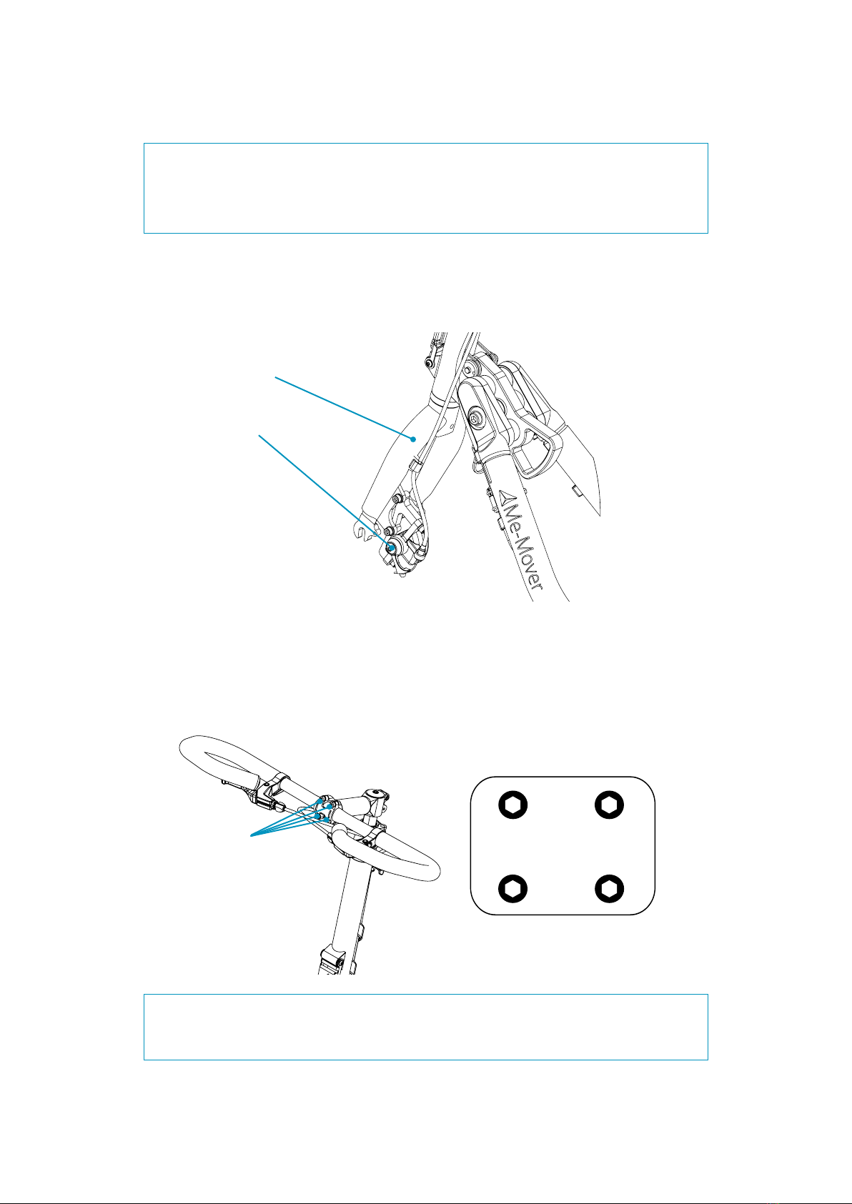
NOTE: Ensure the front fork is pointing in the right direction. The front fork
needs to be bending slightly forward. The brake caliper has to be on the left
side.
4. Loosen all four screws on the handlebar with a 4mm hex key and adjust
the angle of the handlebar to your liking. After alignment, screw all four screws
in halfway. Then use this tightening sequence to tighten them in place:
Front fork
Brake caliper
1
4
3
2
Screws to
loosen / fasten
Cross-fastening sequence
WARNING!
Do not tighten the screws with more than 5Nm.
WARNING!
Do not tighten the screws with more than 5Nm. 5Nm corresponds to a 20cm
wrench with a force of 2,5 kg.
18Chapter
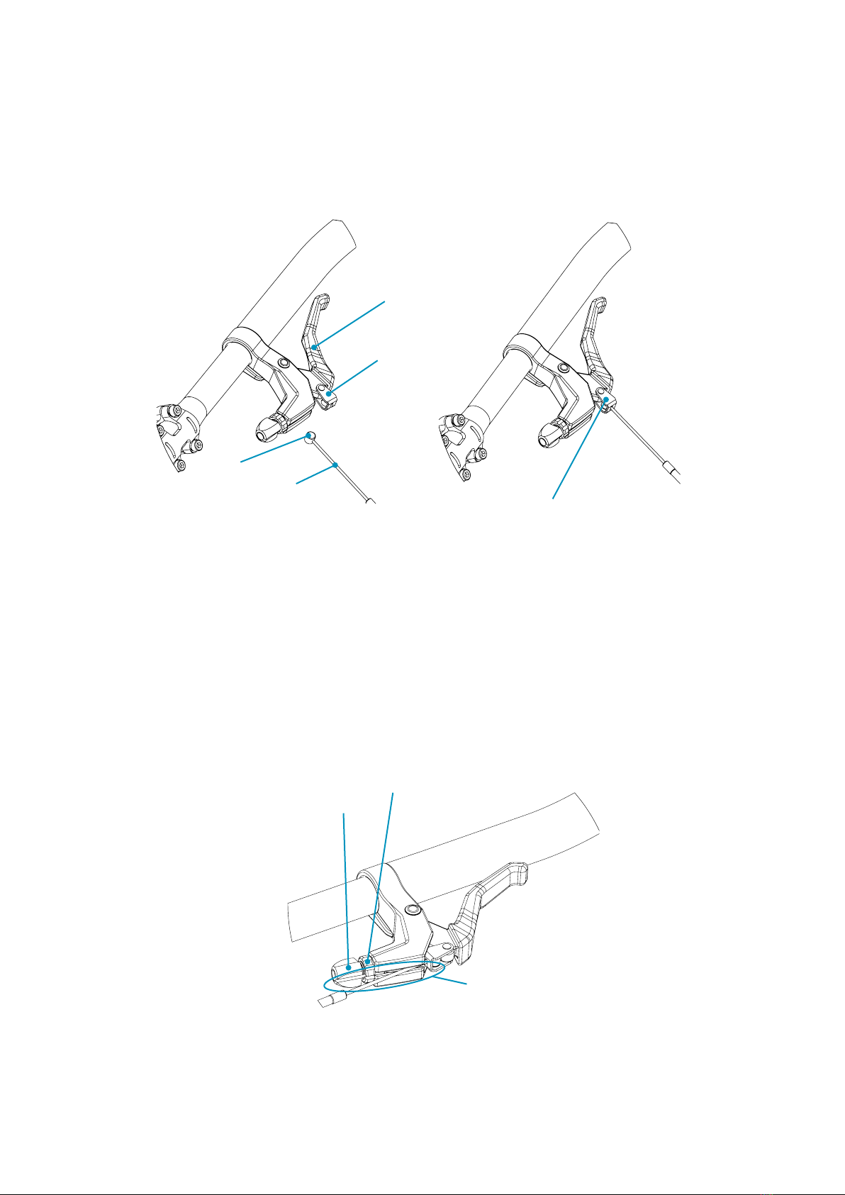
5. Connect the brake cables to the brake handles. Pull the brake handle and
insert the end anchor into the slot in the brake handle.
6. Align the lock nut and adjustment screw and slide the cable into the
groove. If necessary, pull the brake cable housing so more cable is exposed.
Screw the lock nut and adjustment screw tight.
7 Assembly
Brake
handle
Slot
End anchor
Brake
cable End anchor in the slot
NOTE: Please take note of which cable operates the front and the rear brake
when doing this step. There may be local laws regulating how your brakes need
to function.
Lock nut
Adjustment
screw
Groove

19Chapter
7. Mount the front wheel to the front fork. Ensure that the front fork is
pointing forward. Slide the front wheel into the front fork so that the brake disc
is placed between the brake pads in the caliper.
7 Assembly
WARNING!
Always ensure that the front wheel quick release is fastened securely.For
detailed instructions see How to Use Quick Releases on page 15.
8. Fasten the front wheel to the front fork using the front wheel quick
release. Hold the clamp OPEN while you rotate the nut in a clockwise direction.
Rotate the nut until you cannot close the clamp anymore. At this point release
the nut slightly so you can JUST close the clamp.
Brake disc
Brake caliper
Front wheel
Hold the clamp in
OPEN position
Rotate the nut in
clockwise direction

20Chapter
10. Connect the steering column to the rear frame. Press the frame in
between the anges at the steering column at a slightly downward angle.
Then adjust until the two holes are aligned.
9. Remove the safety pin and unscrew the steering column screw using a
6mm hex key.
7 Assembly
Safety pin
Steering
column screw
Steering column
Rear frame Align the holes
Other manuals for FIT
2
Table of contents


