Matrix Fitness S7xe User manual

STEPPER
OWNER’S MANUAL
S7xe
S7x
S5x
S3xe
S3x
stepper_om_r1.6.indd 1 9/9/11 10:11 AM

23
IMPORTANT PRECAUTIONS
SAVE THESE INSTRUCTIONS
Read this GUIDE before using the OWNER’S MANUAL. When using an electrical product, basic precautions should always be
followed, including the following: Read all instructions before using this product. It is the responsibility of the owner to ensure
that all users of this product are adequately informed of all warnings and precautions. If you have any questions after reading this
guide, contact Customer Tech Support at the number listed on the back panel of the OWNER’S MANUAL.
This product is intended for commercial use. To ensure your safety and protect the equipment, read all instructions
before operating.
stepper_om_r1.6.indd 2-3 9/9/11 10:11 AM

4 5
TO REDUCE THE RISK OF ELECTRICAL SHOCK:
Always unplug the unit from the electrical outlet immediately after using, before cleaning, performing maintenance and putting on or
taking off parts.
DANGER
• An appliance should never be left unattended when plugged in. Unplug the entertainment equipment from outlet when not in use
and before putting on or taking off parts.
• This product must be used for its intended purpose described in this Owner’s Guide. Do not use other attachments that are not
recommended by the manufacturer. Attachments may cause injury.
• To prevent electrical shock, never drop or insert any object into any opening.
• Do not remove side covers. Service should only be done by an authorized service technician.
• Never operate the Stepper with the air opening blocked. Keep the air opening clean, free, of lint, hair and the like.
• Never operate the product if it has a damaged cord or plug, if it is not working properly, if it has been damaged, or immersed in
water. Return the unit to a service center for examination and repair.
• Do not carry this unit by entertainment equipment power cord or use cord as handle.
• Keep any of the entertainment equipment power cords away from heated surfaces
• Keep hands and loose clothing away from moving parts.
• Close supervision is necessary when the Stepper is used by or near children or disabled persons.
• Do not use outdoors.
• Do not operate where aerosol (spray) products are being used or where oxygen is being administered.
• Connect this Stepper to a properly grounded outlet only.
• To disconnect, turn all entertainment controls to the off position, then remove plug from outlet.
CAUTION
TO REDUCE THE RISK OF BURNS, FIRE, ELECTRICAL SHOCK OR INJURY TO PERSONS:
• Keep power cord away from heated surfaces. Do not carry this unit by its supply cord or use the cord as a handle.
• Do not use other attachments that are not recommended by the manufacturer. Attachments may cause injury.
• Use the unit only as described in the unit guide and owner’s manual.
• Disconnect all power before servicing or moving the equipment. To clean, wipe surfaces down with soap and slightly damp cloth
only; never use solvents. (See MAINTENANCE)
• The unit should never be left unattended when plugged in. Unplug from outlet when not in use, and before putting on or taking
off parts.
• Do not operate under blanket or pillow. Excessive heating can occur and cause fire, electric shock, or injury to persons.
• At NO time should pets or children under the age of 13 be closer to the unit than 10 feet.
• At NO time should children under the age of 13 use the unit.
• Children over the age of 13 or disabled persons should not use the unit without adult supervision.
• Never operate the unit if it has a damaged cord or plug, if it is not working properly, if it has been dropped or damaged, or
immersed in water. Return the unit to a service center for examination and repair.
• To disconnect, turn all controls to the off position, then remove plug from outlet.
• Do not remove the console covers unless instructed by Customer Tech Support. Service should only be done by an authorized
service technician.
• This unit is not equipped with a free wheel. Pedal speed should be reduced in a controlled manner.
It is essential that your unit is used only indoors, in a climate controlled room. If your unit has been exposed to colder
temperatures or high moisture climates, it is strongly recommended that the unit is warmed up to room temperature before first
time use. Failure to do so may cause premature electronic failure.
WARNING
WARNING
If you experience any kind of pain, including but not limited to chest pains, nausea, dizziness, or shortness of breath, stop
exercising immediately and consult your physician before continuing.
stepper_om_r1.6.indd 4-5 9/9/11 10:11 AM

6 7
ELECTRICAL REQUIREMENTS
The Matrix Stepper has different electrical requirements depending on the model chosen. The chart below should assist you with your
facility planning:
3x / 5x: These products are designed to be self powered and do not require an external power supply source to operate. However,
these units can be AC powered if an optional power cord is purchased. This will power the console at all times and requires no
minimum RPM for operation. These units can be daisy-chained together, up to 4 units per dedicated 15 amp circuit, using a Matrix
daisy-chain cord adapter (sold separately).
3xe / 7x / 7xe: These products must be AC powered. These units can be daisy-chained together, up to 4 units per dedicated 15 amp
circuit, using a Matrix daisy-chain cord adapter (sold separately).
For your safety and for the performance of your Matrix product, the ground on your circuits must be non-looped. Please refer to NEC
article 210-21 and 210-23. Any alterations to the standard Matrix power cords will void all warranties.
DEDICATED CIRCUIT AND ELECTRICAL INFO
All Matrix units require the use of a 15 amp or 20 amp “dedicated circuit,” with a non-looped (isolated) neutral/ground, for the power
requirement. Quite simply this means that each outlet you plug into should not have anything else running on that same circuit. The
easiest way to verify this is to locate the main circuit breaker box, and turn off the breaker(s) one at a time. Once a breaker has been
turned off, the only thing that should not have power to it are the units in question. No lamps, vending machines, fans, sound systems,
or any other item should lose power when you perform this test.
Non-looped (isolated) neutral/grounding means that each circuit must have an individual neutral/ground connection coming from it,
and terminating at an approved earth ground. You cannot “jumper” a single neutral/ground from one circuit to the next.
In addition to the dedicated circuit requirement, the proper gauge wire must be used from the circuit breaker box, to each outlet that
will have the maximum number of units running off of it. If the distance from the circuit breaker box, to each outlet, is 100 ft or less,
then 12 gauge wire may be used. For any distance greater than 100 ft from the circuit breaker box to the outlet, 10 gauge wire must
be used.
GROUNDING INSTRUCTIONS
This product must be grounded. If a unit should malfunction or breakdown, grounding provides a path of least resistance for electrical
current to reduce the risk of electrical shock. This product is equipped with a cord having an equipment-grounding conductor and a
grounding plug. The plug must be plugged into an appropriate outlet that is properly installed and grounded in accordance with local
codes and ordinances.
Connect this exercise product to a properly grounded outlet only.
Never operate product with a damaged cord or plug even if it is working properly. Never operate any product if it appears
damaged, or has been immersed in water. Contact Customer Tech Support for replacement or repair.
WARNING
DANGER
Improper connection of the equipment-grounding conductor can result in a risk of electric shock. Check with a qualified
electrician or serviceman if you are in doubt as to whether the product is properly grounded. Do not modify the plug provided
with the product. If it will not fit the outlet, have a proper outlet installed by a qualified electrician.
This product is for use on a nominal 110-120 Volt circuit and has a grounding plug that looks like the plug in the illustration. Make
sure that the product is connected to an outlet having the same configuration as the plug. No adapter should be used with this
product.
This product must be used on a dedicated circuit. To determine if you are on a dedicated circuit, shut off the power to that circuit and
observe if any other devices lose power. If so, move devices to a different circuit.
stepper_om_r1.6.indd 6-7 9/9/11 10:11 AM

89
BASIC OPERATION
BATTERY CHARGE (3X, 5X ONLY)
The Stepper saves its battery charge by moving into a shutdown mode whenever STEP FASTER appears on the display. If the user
does not maintain a step rate above 35 steps per minute, then a 30-second shutdown process begins.
When the battery voltage is low, LOW BATTERY appears on the display if the unit is moving into the shutdown mode. The following
situation is the time to recharge the battery:
• If no one has used the unit for an extended period of time, the battery may need recharging.
• The unit continues to function with a low battery; however, user and program information is lost once the user stops.
If the battery must be recharged, use the optional power adapter charging unit. The charger should be connected to the Stepper
for a minimum of eight hours to ensure a thorough charge. After a completion of charge, the battery light turns from red into green
(see illustration). If LOW BATTERY still appears on the display after a full charge, the battery could be extinct. Please check with an
authorized service technician for replacing the battery.
CAUTION: The battery stored inside the unit contains hazardous materials to the environment. Proper disposal of the battery is
required by the local law.
stepper_om_r1.6.indd 8-9 9/9/11 10:11 AM

10 11
Our equipment is heavy, use care and additional help if
necessary when moving. Failure to follow these instructions
could result in injury.
LEVELING THE UNIT
Locate a level, stable surface to position the Stepper. The Stepper
has leveling feet located under the foot support. If your Stepper
wobbles in the location where you intended to use it, loosen the lock
nut on the adjusting foot and adjust the feet until stable. Once level,
lock the adjusting feet by tightening the lock nut to the frame.
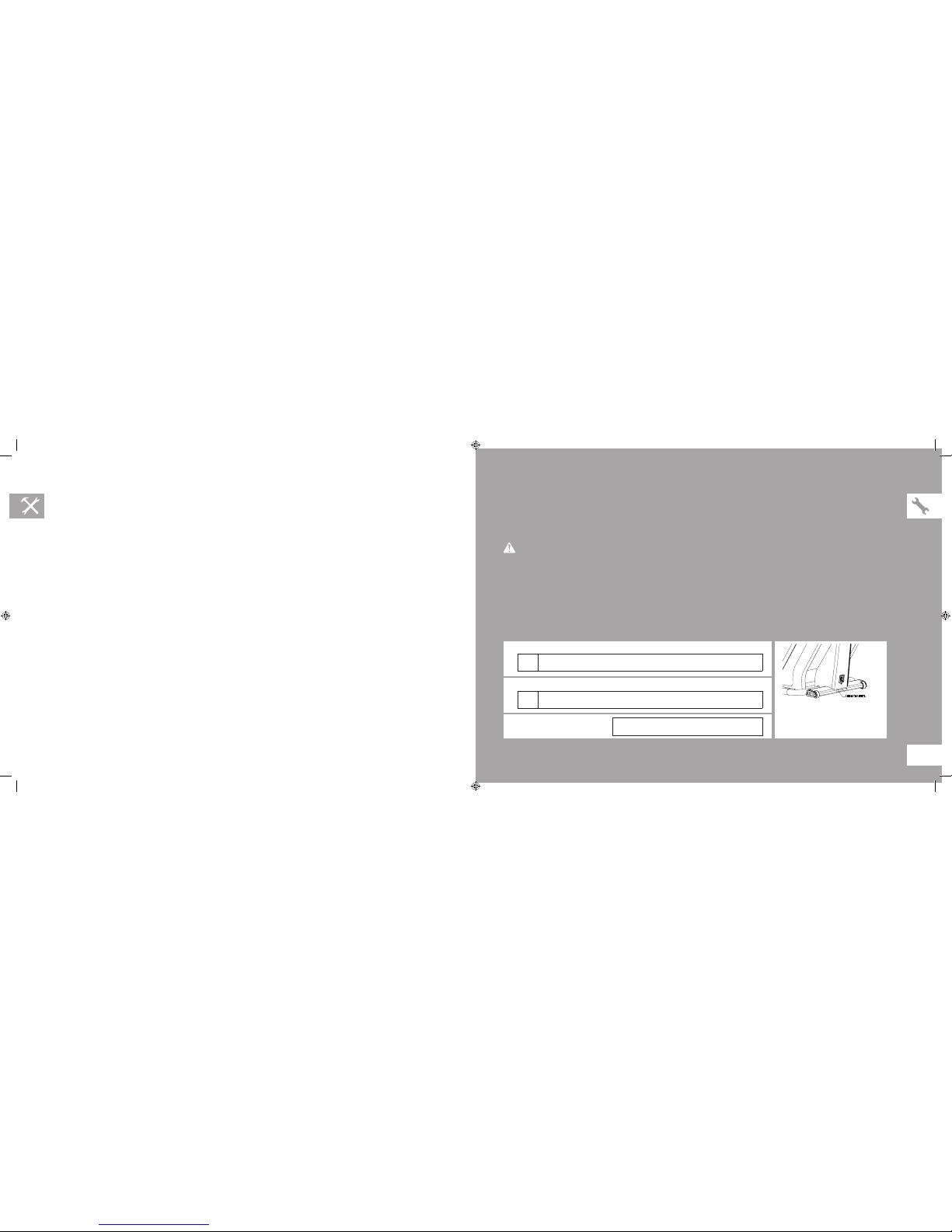
LOCATION OF THE UNIT
Place the unit on a level and stable surface. There should be 2 feet of clearance behind
the unit and one foot in front for the power cord. Do not place the unit in any area that
will block any vent or air openings. These products should not be located in a garage,
covered patio, near water or outdoors.
Never operate product if it has a damaged cord or plug, if it is not working
properly, if it has been damaged, or immersed in water. Contact Customer Tech
Support for examination and repair.
FOOT POSITIONING
Your unit offers a variety of foot positions. Moving your foot to the forward most position of the foot pad increases your step height,
which will create a feel similar to a step machine. Placing your foot toward the back of the foot pad decreases your step height and
creates more of a gliding feel, similar to a smooth walk or run. Always make sure your entire foot is secured on the foot pad. The pedal
motion is dependent.
POWER
If your unit is powered by a power supply, the power must be plugged into the power
jack, which is located in the front of the machine near the stabilizer tube. Some units have
a power switch, located next to the power jack. Make sure it is in the ON position. Unplug
cord when not in use. NOTE: Some units have an ON/OFF switch located behind
the console.
WARNING
WARNING
MOUNTING THE STEPPER
1. Stand behind the unit.
2. While holding both of the rear arm handles, place one foot on
the corresponding footpad. Wait until the footpad comes to a
stop at the bottom of the stroke.
3. Then place your other foot on the opposite pedal.
USING THE HEART RATE FUNCTION
The heart rate function on this product is not a medical
device. While heart rate grips can provide a relative
estimation of your actual heart rate, they should not be
relied on when accurate readings are necessary. Some
people, including those in a cardiac rehab program, may
benefit from using an alternate heart rate monitoring
system like a chest or wrist strap. Various factors,
including movement of the user, may affect the accuracy
of your heart rate reading. The heart rate reading is
intended only as an exercise aid in determining heart
rate trends in general. Please consult your physician.
PULSE GRIPS
Place the palm of your hands directly on the grip pulse
handlebars. Both hands must grip the bars for your heart rate
to register. It takes 5 consecutive heart beats (15-20 seconds)
for your heart rate to register. When gripping the pulse
handlebars, do not grip tightly. Holding the grips tightly may
elevate your blood pressure. Keep a loose, cupping hold. You
may experience an erratic readout if consistently holding the
grip pulse handlebars. Make sure to clean the pulse sensors to
ensure proper contact can be maintained.
3 ft 3 ft
92 cm 92 cm
1 ft 31 cm
3 ft 92 cm
stepper_om_r1.6.indd 10-11 9/9/11 10:11 AM

12 13
WIRELESS HEART RATE RECEIVER
When used in conjunction with a wireless chest transmitter, your heart rate can be transmitted wirelessly to the unit and displayed
on the console.
Prior to wearing the wireless chest transmitter on your chest, moisten the two rubber electrodes with water. Center the chest strap
just below the breast or pectoral muscles, directly over your sternum, with the logo facing out. NOTE: The chest strap must be tight
and properly placed to receive an accurate and consistent readout. If the chest strap is too loose, or positioned improperly, you may
receive an erratic or inconsistent heart rate readout.
BACKSIDE OF CHEST TRANSMITTER
APPLY MOISTURE HERE
LOGO
TROUBLESHOOTING
& MAINTENANCE
Heart rate monitoring systems may be inaccurate. Over exercising may result in serious injury or death. If you feel faint, stop
exercising immediately.
WARNING!
stepper_om_r1.6.indd 12-13 9/9/11 10:11 AM

14 15
RECOMMENDED CLEANING TIPS
Preventative maintenance and daily cleaning will prolong the life and look of your equipment.
SOLUTION: Follow these tips:
• Position the equipment away from direct sunlight. The intense UV light can cause discoloration on plastics.
• Locate your equipment in an area with cool temperatures and low humidity.
• Clean with a soft 100% cotton cloth.
• Clean with soap and water or other non-ammonia based all purpose cleaners.
• Wipe foot pads, handles, heart rate grips, and handlebars clean after each use.
• Do not pour liquids directly onto your equipment. This can cause damage to the equipment and in some cases electrocution.
• Check pedal motion and stability.
• Adjust leveling feet when equipment wobbles or rocks.
• Maintain a clean area around equipment, free from dust and dirt.
• For cleaning 7xe displays, use distilled water in an atomizer spray bottle. Spray distilled water onto soft, clean, dry cloth and wipe
display until clean and dry. For very dirty displays, adding vinegar is recommended.
WARNING: Do not plug the treadmill in until the motor cover has been reinstalled.
CHECK FOR DAMAGED PARTS
DO NOT use any equipment that is damaged or has worn or broken parts. Use only replacement parts supplied by Matrix Fitness.
MAINTAIN LABELS AND NAMEPLATES. Do not remove labels for any reason. They contain important information. If unreadable
or missing, contact Matrix Fitness Systems for a replacement. 1-866-693-4863, www.matrixfitness.com
MAINTAIN ALL EQUIPMENT Preventative maintenance is the key to smooth operating equipment. Equipment needs to be
inspected at regular intervals. Defective components must be replaced immediately. Improperly working equipment must be kept out
of use until it is repaired. Ensure that any person(s) making adjustments or performing maintenance or repair of any kind is qualified
to do so. Matrix Fitness Systems will provide service and maintenance training at our corporate facility upon request or in the field if
proper arrangements are made.
CARE AND MAINTENANCE
HOW DO I CLEAN MY MACHINE?
Clean with soap and water cleaners only. Never use solvents on plastic parts. Cleanliness of your stepper and its operating
environment will keep maintenance problems and service calls to a minimum. For this reason, Customer Tech Support recommends
that the following preventive maintenance schedule be followed.
DAILY
• Clean entire machine using water and mild detergent such as “Simple Green”, or other Matrix approved solution (cleaning agents
should be alcohol and ammonia free).
QUARTERLY
• Check all connecting joint areas for tightness of bolt assemblies.
CONSOLE RESPONSIVENESS ISSUES (CONSOLE REBOOT):
FOR 3XE, 7X, AND 7XE CONSOLES
Press and HOLD the Channel Up and Channel Down Button until you hear a Beep. Your console will reset.
stepper_om_r1.6.indd 14-15 9/9/11 10:11 AM

17
STEPPER ASSEMBLY
There are several areas during the assembly process that special attention must be paid. It is very important to follow the assembly
instructions correctly and to make sure all parts are firmly tightened. If the assembly instructions are not followed correctly, the
stepper could have frame parts that are not tightened and will seem loose and may cause irritating noises. To prevent damage to
the stepper, the assembly instructions must be reviewed and corrective actions should be taken.
Before proceeding, find your unit’s serial number located..
ENTER YOUR SERIAL NUMBER AND MODEL NAME IN THE BOXES BELOW:
» Refer to the SERIAL NUMBER and MODEL NAME when calling for service.
*The console serial number can be found in the Manager Mode.
WARNING
SERIAL NUMBER LOCATION
CONSOLE SERIAL NUMBER:
MODEL NAME: MATRIX
FRAME SERIAL NUMBER:
SERIAL # PLACEMENT
stepper_om_r1.6.indd 16-17 9/9/11 10:11 AM

18 19
Z07
Z06 ARC WASHER
4
8
Z02
Z09
Z03
Z01
Z05
LOCK WASHER
BUTTON HEAD BOLT(M5x15L)
8
4
BUTTON HEAD BOLT(M8x16L)
SOCKET HEAD BOLT(M8x16L)
DESCRIPTION
FASTENERS
SKETCH
2
8
4
QUANTITY
BUTTON HEAD BOLT(M8x40L)
SCREW SET
REFERENCE
Z02 LOCK WASHER 4
Z02 LOCK WASHER 2
Z34 SOCKET HEAD BOLT(M8x25L) 2
PACKAGE COLOR
WHITE
WHITE
BLUE
BLACK
YELLOW
ORANGE
ORANGE
ORANGE
BLACK
RED
Z10 BUTTON HEAD BOLT(M8x45L) 2YELLOW
Z04 LOCK WASHER 3GREEN
Z05 BUTTON HEAD BOLT(M8x16L) 3GREEN
6mm ALLEN WRENCH
PHILLIPS DRIVER(6x130mm)
Z03
Z02
PURPLE
PURPLE
1
1
Z01
5mm ALLEN WRENCH PURPLE2
REQUIRED FASTENERS REQUIRED TOOLS
stepper_om_r1.6.indd 18-19 9/9/11 10:11 AM

20 21
6
Z01
Z02
Z02
Z01
Z02
Z01
LOCK WASHER Qty: 8
SOCKET HEAD BOLT(M8x16L) Qty: 8
ASSEMBLY STEP 2
A Open HARDWARE BAG 2.
B Attach MANUAL INCLINE LIFT LEVER to GUIDE
RAIL SET using 4 BOLTS (D), 4 FLAT WASHERS
(E), 4 SPRING WASHERS (F) and 4 NUTS (G).
C Align GUIDE RAIL SET with MAIN FRAME as
shown.
D Lift up on the MANUAL INCLINE LIFT LEVER
and place it in one of the holes inside the MAIN
FRAME.
E Attach the GUIDE RAIL SET to the MAIN FRAME
using 4 BOLTS (G), 4 FLAT WASHERS (H), 4
SPRING WASHERS (I) and 4 NUTS (J).
BLACK HARDWARE BAG CONTENTS
ASSEMBLY STEP 1
A Open HARDWARE BAG 1.
B Attach the STABILIZER TUBE to the MAIN
FRAME using 2 BOLTS (A), 2 SPRING
WASHERS (B) and 2 ARC WASHERS (C) on
each side.
Z07 Qty: 4
Z09 BUTTON HEAD BOLT(M5x15L) Qty: 4
BUTTON HEAD BOLT(M8x40L)
Z02 LOCK WASHER Qty: 2
RED HARDWARE BAG CONTENTS :
Z09
Z09
Z02
Z07
stepper_om_r1.6.indd 20-21 9/9/11 10:11 AM

22 23
6
Z41
Z34
CONSOLE SCR EW
ASSEMBLY STEP 4
A Open HARDWARE BAG 3.
B Carefully pull the CONSOLE CABLE through
the CONSOLE MAST using the twist tie located
inside the CONSOLE MAST.
C Attach CONSOLE MAST to MAIN FRAME
using PRE-INSTALLED BOLTS AND
WASHERS.
D Slide WAVY WASHER (L) over CRANK
followed by PEDAL ARM as shown. Rest
PEDAL ARM WHEEL on GUIDE RAIL.
E Attach the PEDAL ARM to the CRANK using 1
FLAT WASHER (K), 1 SPRING WASHER (B)
and 1 BOLT (M).
F Repeat steps D–E on the opposite side of the
stepper.
Z34 SOCKET HEAD BOLT(M8x25L) Qty: 2
BLUE HARDWARE BAG CONTENTS :
ASSEMBLY STEP 3
A Open HARDWARE BAG 2.
B Attach the GUIDE RAIL SET to the MAIN
FRAME using 4 BOLTS (F), 4 SPRING
WASHERS (E) and 4 FLAT WASHERS (D).
C Attach the GUIDE RAIL SET to the INCLINE
BRACKET using 4 BOLTS (G), 4 FLAT
WASHERS (H), 4 SPRING WASHERS (I) and
4 NUTS (J).
6
Z04 x 3
Z05 x 3
Z03
Z06
Z05 x 4
Z03
Z06
Z05
Z06
Z06
Z10
Z02
Z06 ARC WASHER Qty: 8
Z03
Z05 BUTTON HEAD BOLT(M8x16L)
Qty: 2
Qty: 4
SCREW SET
Z10 BUTTON HEAD BOLT(M8x45L) Qty: 2
Z04 LOCK WASHER Qty: 3
BLUE HARDWARE BAG CONTENTS :
ASSEMBLY COMPLETE!
7XE / 7X / 5X CONSOLE ASSEMBLY
stepper_om_r1.6.indd 22-23 9/9/11 10:11 AM

24 25
STEPPER OPERATION
6
Z41
Z34
CONSOLE SCR EW
ASSEMBLY STEP 4 (CONT.)
A Open HARDWARE BAG 3.
B Carefully pull the CONSOLE CABLE through
the CONSOLE MAST using the twist tie located
inside the CONSOLE MAST.
C Attach CONSOLE MAST to MAIN FRAME
using PRE-INSTALLED BOLTS AND
WASHERS.
D Slide WAVY WASHER (L) over CRANK
followed by PEDAL ARM as shown. Rest
PEDAL ARM WHEEL on GUIDE RAIL.
E Attach the PEDAL ARM to the CRANK using 1
FLAT WASHER (K), 1 SPRING WASHER (B)
and 1 BOLT (M).
F Repeat steps D–E on the opposite side of the
stepper.
Z34 SOCKET HEAD BOLT(M8x25L) Qty: 2
BLUE HARDWARE BAG CONTENTS :
ASSEMBLY COMPLETE!
3X / 3XE CONSOLE ASSEMBLY
stepper_om_r1.6.indd 24-25 9/9/11 10:11 AM

26 27
MANAGER PREFERENCE MODE
3X AND 5X CONSOLES:
This section allows a user to manipulate default settings for the machines. It may be accessed by pressing the Level Up/Level
Down keys simultaneously for 5 seconds. To change a setting, press “Enter” on the keypad and use the Level buttons and numeric
keypad to change the values. Pressing “Enter” again will save the change. Pressing “Back” will bring you to the previous menu. To
exit manager’s mode, hold “Stop” down for 5 seconds. Below is a list of the settings.
3XE, 7X AND 7XE CONSOLES:
This section allows a user to manipulate default settings for the machines. It may be accessed by pressing “ENTER”, 1, 0, 0, 1,
“Enter”. To change a setting, press “Enter” on the keypad and use the Level buttons and numeric keypad to change the values.
Pressing “Enter” again will save the change. Pressing “Back” will bring you to the previous menu. To exit manager’s mode, press the
“Home” key. Below is a list of the settings.
Maximum Time
Default Time
Default Level
Default Age
Default Weight
Accumulated Distance
Accumulated Time
Software Version
Timer Mode
CONSOLE DESCRIPTION:
The Matrix machine is inspected before it is packaged. It is shipped in two pieces: the base
and the console. Carefully unpack the unit and dispose of the box material.
Default Incline
Speed/Distance Mode
Out of Order
Gender
Language
Sound Mode
Incline Reset
stepper_om_r1.6.indd 26-27 9/9/11 10:11 AM

28 29
S3X CONSOLE DESCRIPTION
Note: There is a thin protective sheet of clear plastic on the overlay of the console that should be removed before use.
A) WORKOUT KEYS: Simple program view and selection buttons.
B) GO: One Touch Start.
C) ENTER: To confirm each program setting.
D) UP/DOWN LEVEL: Use to adjust level selection.
E) UP/DOWN TIME: Use to adjust workout time.
F) STOP: Ends workout and shows workout summary data.
G) COOL DOWN: Puts the console into Cool Down mode.
H) TOGGLE DISPLAY: Allows user to select what information is displayed on each of the three windows on the console. Press
and hold to enable/disable scrolling.
stepper_om_r1.6.indd 28-29 9/9/11 10:11 AM

30 31
S3XE CONSOLE DESCRIPTION
Note: There is a thin protective sheet of clear plastic on the overlay of the console that should be removed before use.
A) MULTI-PURPOSE KEYS: Keys have different functions depending on each screen.
B) GO: One Touch Start.
C) ENTER: Use to confirm each program setting.
D) BACK: Use to undo or go back one screen.
E) UP/DOWN LEVEL: Use to increase or decrease resistance level.
F) UP/DOWN TIME: Use to adjust workout time.
G) STOP: Ends workout and shows workout summary data.
H) NUMBER KEYPAD: Workout data input for workout setup. Resistance level adjustment during workout.
I) COOL DOWN: Puts the console into Cool Down mode.
S3XE ENTERTAINMENT ZONE
J) TV: Will take the user to directly the TV screen.
K) VOLUME UP/DOWN: Adjusts the volume output through the headphone jack of either integrated console TV or iPod output.
L) NUMBER KEYPAD: Allows for easy TV channel selections.
M) CHANNEL UP/DOWN: Allows for channel selection.
N) DISPLAY MODE: Allows user to cycle through console display options, iPod, TV or profile display.
O) LAST CHANNEL: Allows the user to cycle between the current channel and the previous channel they were viewing.
P) HOME: Changes the channel to the channel defined as Home.
Q) CC/MUTE: Press to cycle through the different closed caption and mute configurations.
stepper_om_r1.6.indd 30-31 9/9/11 10:11 AM

32 33
S5X CONSOLE DESCRIPTION
Note: There is a thin protective sheet of clear plastic on the overlay of the console that should be removed before use.
A) WORKOUT KEYS: Simple program view and selection buttons.
B) GO: One Touch Start.
C) ENTER: To confirm each program setting.
D) UP/DOWN LEVEL: Easy information and level selection.
E) UP/DOWN TIME: Easy information and time adjustment.
F) STOP: Ends workout and shows workout summary data.
G) NUMBER KEYPAD: Workout data input for workout setup. Level adjustment during workout.
H) COOL DOWN: Puts the stepper into Cool Down mode.
I) FAN: Allows for fan speed selection (fan has three operating speeds.)
stepper_om_r1.6.indd 32-33 9/9/11 10:11 AM

34 35
S7X CONSOLE DESCRIPTION
Note: There is a thin protective sheet of clear plastic on the overlay of the console that should be removed before use.
A) MULTI-PURPOSE KEYS: Keys have different functions depending on each screen.
B) GO: One Touch Start.
C) ENTER: To confirm each program setting.
D) UP/DOWN LEVEL: Easy information and level selection.
E) UP/DOWN TIME: Easy information and time adjustment.
F) STOP: Ends workout and shows workout summary data.
G) NUMBER KEYPAD: Workout data input for workout setup. Level adjustment during workout.
H) COOL DOWN: Puts the stepper into Cool Down mode.
I) FAN: Allows for fan speed selection (fan has three operating speeds.)
S7X ENTERTAINMENT ZONE
J) POWER: If add-on TV is present, acts as the power control button. If add-on TV is not present, acts as a display toggle button.
K) IPOD®: Will take the user directly to the iPod screen to allow for iPod control and playlist selection.
L) VOLUME UP/DOWN: Adjusts the volume output through the headphone jack of either integrated console TV or iPod output.
M) NUMBER KEYPAD: Allows for easy TV channel selections.
N) CHANNEL UP/DOWN: Allows for channel selection.
O) DISPLAY MODE: Allows user to cycle through console display options, iPod, TV or profile display.
P) LAST CHANNEL: Allows the user to cycle between the current channel and the previous channel they were viewing.
stepper_om_r1.6.indd 34-35 9/9/11 10:11 AM

36 37
S7XE CONSOLE DESCRIPTION
The S7xe has a fully integrated touch screen display. All information required for workouts is explained on screen. Exploration of the
interface is highly encouraged. The information explaining how to program for various workouts will give an explanation about the
contents of each screen on the S7xe.
A) QUICK START/GO: One Touch Start and Quick Start.
B) STOP: Ends workout and shows workout summary data.
C) COOL DOWN: Puts stepper into Cool Down mode. Cool Down time is dependent on the length of the workout. Workouts 19
minutes and shorter will have a cool down length of 2 minutes. Workouts 20 minutes and longer will have a cool down length
of 5 minutes.
S7XE ENTERTAINMENT ZONE
D) IPOD®: Will take the user directly to the iPod screen to allow for iPod control and playlist selection.
E) VOLUME UP/DOWN: Adjusts the volume output through the headphone jack of either add-on TV, integrated console TV
or iPod output.
F) NUMBER KEYPAD: Allows for easy TV channel selections. These buttons work for either the add-on TV or the integrated
console TV.
G) CHANNEL UP/DOWN: Allows for channel selection on either the add-on TV or the integrated console TV.
H) DISPLAY MODE: Allows user to cycle through console display options, iPod, TV or profile display.
I) LAST CHANNEL: Allows the user to cycle between the current channel and the previous channel they were viewing.
stepper_om_r1.6.indd 36-37 9/9/11 10:11 AM

38 39
3X WORKOUT DESCRIPTIONS
QUICK START OPERATION
Press the GO button and the machine will enter into a manual
mode of operation. All energy expenditure values will be
calculated using the default weight measurement.
MANUAL WORKOUT OPERATION
Manual is a workout that allows you to manually adjust the level
values at anytime. The manual workout also contains a setup
screen which allows you to input your weight to help calculate a
more accurate caloric burn rate.
To enter into this workout on a 5x, use the following guidelines:
1) Press SELECT PROGRAM button. Press SELECT or
wait 5 seconds. Selecting START will start the program.
2) Select TIME by using the UP or DOWN ARROW
KEYS. Press SELECT or wait 5 seconds. Selecting
START will start program.
3) Select WEIGHT by using the UP or DOWN ARROW
KEYS. Press START or SELECT to begin workout.
Display will show “Starting 3, Starting 2, Starting 1.”
LEVEL BASED PROGRAMS
The following instructions will guide you through the simple
steps to select Intervals, Rolling, Fat Burn and Random
workouts.
1) Press the PROGRAM button. Press SELECT or wait 5
seconds. Selecting START will start the program.
2) Select LEVEL by using the UP or DOWN ARROW
KEYS. You can change the level at anytime during the
workout. Press SELECT or wait 5 seconds. Selecting
START will start program.
3) Select TIME by using the UP or DOWN ARROW
KEYS. Press SELECT or wait 5 seconds. Selecting
START will start program.
4) Select WEIGHT by using the UP or DOWN ARROW
KEYS. Press START or SELECT to begin workout.
Display will show “Starting 3, Starting 2, Starting 1.”
USER DEFINED PROGRAMS
FIT TEST WORKOUT OPERATION
Fit Test program is to monitor the development of your
cardiovascular system and measure your fitness level based on
your average heart rate during specific test stages. When the
5-minute test is completed, the display provides a fitness score
and fitness category.
To enter into this workout on a 3x, use the following guidelines:
1) Select the FIT TEST button.
2) Select age using the UP or DOWN ARROW KEYS.
Press SELECT or wait 5 seconds.
3) Select gender using the UP or DOWN ARROW KEYS.
Press SELECT or wait 5 seconds.
4) Select weight using the UP or DOWN ARROW KEYS.
Press START or SELECT to begin workout. Console will
display: Starting 3, Starting 2, Starting 1.
5) Display will read results of the FIT TEST.
FIT TEST
This test measures cardiovascular fitness and proves an
estimated sub-maximal VO2 result. It is based on power output
according to ACSM standards and was developed by the
Cooper In stitute (© www.cooperinstitute.org)
User RPMs must remain between 60-80 RPM during the test.
The test will end when the user can no longer maintain this speed.
Use of a heart rate strap is optional but provides more data.
The test starts at a low intensity level and gradually increases
in intensity (difficulty) every 2 minutes. As it increases, the user
must maintain 60-80RPM to advance to the next level. The test
could take upwards of 30+ minutes for very fit individuals. Once
the test ends a recovery period (cool down) will begin, and the
user’s results are calculated and displayed. Results are based
on the number of stages completed:
Stage Complete:
1 Well Below Average
2 Well Below Average
3 Below Average
4 Below Average
5 Average
6 Average
7 Above Average
8 Above Average
9+ Well Above Average
stepper_om_r1.6.indd 38-39 9/9/11 10:12 AM
This manual suits for next models
4
Table of contents
Other Matrix Fitness Stepper Machine manuals