manuals.online logo
Brands
  1. Home
  2. •
  3. Brands
  4. •
  5. Meade
  6. •
  7. Telescope
  8. •
  9. Meade 2080/LX6 Wiring diagram

Meade 2080/LX6 Wiring diagram

@_
....•
~I~
. i
.
.
VeL 0689-1
Supplementary Instructions
Meade 8" Model
2080/LX6
and 10" Model
2120/LX6
Schmidt-Cassegrain Telescopes
with
Quartz Electronic Drive System
Meade Instruments Corporation
1675 Toronto Way, Costa Mesa, Ca 92626· (714) 556-2291
©
1939
- 2 -
I {
WARNING
NEVER ATTEMPT TO OBSERVE THE
SUN
THROUGH
YOUR MEADE TELESCOPE OBSERVING THE SUN,
EVEN FOR THE SHORTEST FRACTION OF A SECOND,
WILL CAUSE INSTANT AND IRREVERSIBLE EYE
DAMAGE. WHEN OBSERVING DURING THE DAYTIME,
00 NOT POINT THE TELESCOPE EVEN CLOSE TO
THE SUN.
WHEN USING YOUR TELESCOPE, PLEASE KEEP IN
MIND THAT IT IS A PRECISION INSTRUMENT. WHILE
NOT OVERLY FRAGILE, THE TELESCOPE CAN BE
DAMAGED BY IMPROPER USE OR CARELESSNESS,
SUCH,," AS, FORCING THE MANUAL LOCKS OR
DROPPING THE ELECTRONIC COMMAND CENTER.
SUCH ABUSE IS NOT COVERED BY THE WARRANTY.
FOR PROPER UTILIZATION OF YOUR MEADE LX6
SCHMIDT-CASSEGRAIN, A THOROUGH READING OF
THIS SUPPLEMENTARY MANUAL IS ESSENTIAL
PLEASE READ ALL CONTENTS OF THIS MANUAL
BEFORE ATTEMPTING TO OPERATE THE
TELESCOPE.
.1
I
. I
I
- 3 -
Contents
A. Introduction
5
1. Optics
2.
Electronics
3.
This Manual
4. f/6.3
Optical System
5
5
5
5
B.
LX6
Power Panel
6
1.
Ammeter.
2.
Power Indicator
3. OntOff
Switch .
4.
Northern/Southern Switch
5.
Dec Motor Output . . . . .
6.
Electric Focuser Output
7.
Illuminated Reticle Output
8.
Electronic Command Center Socket
9.
Power Input Socket
10.
C.A.T. Socket ..
11.
Encoders Socket .
6
7
7
7
7
7
7
7
7
7
8
C.
Electronic Command Center
8
r.
Map Light
2. DRS Buttons
3.
DRS Display
4. Drive Corrector Control Buttons
5.
Electric Focuser Buttons
6.
Map Light Button .•••..
7. 2X18X
Slide Switch .•..•
8.
Quartz/Manual Slide Switch
9.
Variable Speed Knob . . .
10.
Reticle Adjustment Knob
8
8
8
8
9
9
9
9
9
9
D. Operation
9
1.
AC Operation
2. DC Operation
3.
Battery Pack .
9
10
10
- 4 -
E. 9
x
60 Polar Viewfinder
10
1. The Illuminated Reticle
2.
Focusing the Viewfinder
3.
Finding the Celestial Pole
10
10
11
F.
Magnetic Compass •......
12
1.Setting the Magnetic Declination
2.
Compass Installation
3.
Finding True North
12
13
14
G.
Azimuth Control
17
H. Deluxe Latitude Adjuster
17
I. Troubleshooting the LX6 Drive System
18
J.
Specifications . . . . . . . • . . • • . .
19
5
A. Introduction
Congratulations on your purchase of the Meade
LX6
model telescope These telescopes are the latest in a
long line of Meade Schmidt-Cassegrain telescope models, and as such they represent the absolute pinnacle
in state-of-the-art telescope design tor the serious amateur. Important advances in all three major areas of
telescope design - optics, mechanics, and electronics - have been incorporated into these telescopes.
1.Optics
Perhaps the most significal)t
advancement
in commercial telescopes since the introduction of the
Schmidt-Cassegrain itself, the Meade
fl6.3
optical system results in numerous advantages over the traditional
f/10
telescope system. Fields of
view
are 59% wider, images are 2
112
times brighter, and photographic times
are 60% faster than those obtained with
f/10
telescopes. Because of their computer-optimized ultra high
contrast battling, all of this is possible without any compromise of resolution or performance on high power
lunar and planetary work.
2. Electronics
The heart' of every LX6 system is a dedicated microprocessor that continuously controls, with quartz
precision, all important electronic operations of the telescope, from the drive-rate frequency input
to
the main
RA pulse motor, to the Electronic Command Center's multi-functioned digital readouts.
The advanced-design Power Panel allows virtually
every
modern electronic
accessory
you might wish to add
to your LX6 to be plugged into the telescope - from
a
simple Dec motor to the Meade *CAT" Computer Aided
Telescope system.
3.
This Manual
This supplementary manual explains in detail the operation and application of those features unique to Meade
8" and, 10~ I..:X6.Schmldt-Casseqralru.telescopes, Refer to the standard Model
2080/2120
Instruction
Manual for complete detailed information regarding set-up and operation of your telescope.
4. f/6.3
Optical System
The fl6.3 optical system of the LX6 can be used with aU accessories offered
tor
the fl10 systems, and the
Model
2080/2120
Instruction Manual covers the operation of the optical tube assembly. The only change
involves, the Serles VI drop-in filters. The fl6.3 tube assembly, in order to provide full 3Smm film coverage,
does not have the recess for these filters. The eyepiece thread-in filters must be used
if
filters are required.
\\'\\/\\'. fVlanuals1
ib.con1
- G -
MEADE
~@2J
©@[['O
MICROPROCESSOR
* ~
N
S
CONTROLLED
\fg
®
[§=:J
LX QUARTZ PULSE DRIVE On Oft
@
@
Current (rnA x 1000).
Encoders
(1)
Ammeter
(2)
Power Indicator
(3)
On/Off Switch
(4)
Northern/Southern Switch
(5)
Dec Motor Output
(6)
Electric Focus Output
(7)
Illuminated Reticle Output
(8)
Electronic Command Center Socket
(9)
Power
Input
Socket
(10)
CAT.
Socket
(11)
Encoders Socket
Fig ..
1:
LX6
Power Panel
B. LX6 Power Panel
The Meade
LX6
Quartz drive system has several built-in features for simplifying the operation of the
telescope. Output jacks are provided on the Power Panel for some of the more common accessories,
eliminating the need for separate Battery Packs.
1.Ammeter
To estimate the operating time of the telescope, divide the amp hour rating of the power source
by
the power
usage. For example, the ammeter reads from 0 to 2000 mA (0 to 2 amps), so if the needle is positioned over
the second mark, the telescope is using 400 rnA or.4 amp. When the batteries are fully charged, the Battery
Pack amp hour rating is .5 (the Meade 600 Power Cell has a 5 amp hour:rating). So, the operating time of the
telescope when using the Battery Pack when the ammeter is showing a power usage of 400 mA would be
abouL5L4
=
1.25 hours, Note: Actual operating time will depend on many factors such as the condition of the
batteries and outside temperature.
An important feature on the
LX6
telescope
is
the ammeter. This meter shows the power usage of the
telescope. When the telescope
is
powered from an AC source
or a
car battery, the amount of current being
used is not important because the power available
is
essentially unlimited. But when the telescope
is
powered
from a small power cell (such as a 12 volt, 5 amp hour video camera battery) or from the supplied Battery
Pack, the telescope operating time will vary, depending on the power usaqe.
- 7 -
2. Power Indicator
The red Power Indicator light is illuminated anytime the ON/OFF switch is in the ON position, and indicates
that power is being supplied to the telescope.
3. On/Off Switch
This switch turns on and off the power to the telescope.
4. Northern/Southern SWitch
The Northern/Southern (N-S) switch supplied on the Meade LX6 Schmidt-Cassegrains allows operation of the
telescope anywhere in the workt Moving the switch to the Southern (S) position reverses the telescope's
tracking direction. Note: Once set, unless the telescope is operated in a different hemisphere, this switch
need never be used again.
Note: The 'N-S switch must be set to the correct position before turning the ON/OFF switch to the ON
position. Moving the Northem/Southern switch after the telescope is turned on will result in incorrect
tracking. . .
5. Dec Motor Output
The "Declination Motor" socket is used for the optional #39 Declination
motor
assembly. The hand-held
Electronic Command Center is required for use of the Declination motor and will operate the Declination
Motor at the 2X guide correcting speed and the 8X image scanning speed.
6. Electric Focuser Output
The optional Meade #1200A Electric Focuser may also be plugged directly into the LX6 power panel by using
the Electric Focuser jack. The Electronic Command Center may now be used to control the Electric Focuser
to achieve very precise focusing of the telescope.
7. Illuminated Reticle Output
The optional Illuminated Retic{e can be plugged directly into the LX6 power panel reticle jack, eliminating the
need for a separate battery box. The Reticle Adjust Knob (located on the Electronic Command Center)
controls the brightness of the reticle.
8. Electronic Command Center Socket
The Electronic Command Center Socket resuHs in the "pluq-in" capability of the LX6. By simply plugging the
Electronic Command Center into the socket. the full range of LX6 features are made available. See below for
description of the Electronic Command Centerfeatures.
9. Power Input Socket
Each LX6 includes power cords for three different methods of powering the telescope: Directly from auto
cigarette fighter plugs; directly from 115 v.AC home outlets; and from a Battery Pack (using 10 user supplied
AA-sized batteries). Each of these power cords plugs into the Power Input socket to supply power to the
telescope.
1
O.
CAT Socket
When the optional Model 9008 CAT Computer Aided Telescope system is plugged into this socket, the CAT
receives all encoder information and power directly from the Power Panel. eliminating unnecessary wires.
11. Encoders Socket
-8 -
When encoders are added to the telescope, either for the CAT or Digital Readout System (DRS). they are
plugged into this socket
C. Electronic Command Center (ECC)
The hand-held Electronic Command Center plugs directly into the LX6 power panel "Command Center"
socket (#8, Fig. 1) and is the heart of the LX6 concept. Virtually all telescope functions are put at your
fingertips, making separate' Battery Packs and hand boxes obsolete. At the same time,
if
a simple, quick
observing session is planned which will not require the sophisticated features of the LX6 , the telescope may
be operated without the Electronic Command Center, reducing power consumption. This may be useful if you
wish to power the telescope from the Battery Pack.
1.
Map Ught
The Electronic Command Center (ECC)
includes a red L.E.D. located at the top of the
handbox. Depressing the "Map" button
\d'6,
Fig. 2) illuminates this light for reading star
maps or charts during an observing session.
2. DRS Buttons
These buttons control the Digital Readout
System functions. See section I for. detailed
information on the use of the DRS. Note: It the
DRS is not installed, these buttons are
non-functional.
3. DRS Display
This area contains the bar L.E.D.'s (Ught
Emitting Diodes) and numeric L.E.D:s which
make up the DRS. See section I for detailed
information. Note: If the DRS is not installed.
this display is blank.
4. Drive Corrector Control Buttons
These buttons are used to electronically move
the telescope. The -E" and
W
buttons move
the telescope in Right Ascension using the
main drive motor, The "NW and "S" buttons
move the telescope in Declination using the
optional
#39
Dec Motor. If this motor is not
attached, these two buttons are non-functional.
The speed at which the telescope moves when
usinq these buttons is determined by the
position of the 2Xl8X slide switch (see #7,
below).
2
Meade
[QJ][QJ][QJ]
Init Mode Set
Locai ,I-I
"1"11'/-,
:erO.CJ.O.O
~ ·,.::n:;·
Cf .CI
Freq'-'. '-,. '-'. '-I
N
[QJ]
w[QJ] [QJ]E
[(Q)}
S
(1) Map Light
(2) DRS Buttons
(3) DRS Display
(4) Drive Corrector8uttons
(5) Focus Buttons
(6) Map Light Button
8
(7)
2Xl8X
Slide Switch
(8) Quartz/Manual Slide
Switch
(9) Variable Speed Knob
(10) Reticle Adjust Knob
Fig. 2: Electronic Command Center (ECC)
-9 -
5. Electric Focuser Buttons
. Add the optional Meade #1200A Electric Focuser, and ultraprecise microfocusing is at your fingertips. Simply
depress the ECC's focus pushbuttons (#5, Fig. 2) to obtain the sharpest lunar and planetary focus possible.
Coarse focusing is accomplished with the telescope's manual focus knob.
6. Map Light Button
When pushed, this button illuminates the LE.D. located at the top of the ECC. (See #1 Map Light on page 8.)
7. 2X18X
Slide Switch
As described previously, when anyone of the four Drive Corrector buttons is pressed, the telescope moves in
the labeled direction. The speed at which the telescope moves is determined by the
2X18X
slide switch.
When in the 2X position, the telescope moves twice the tracking rate in the Right Ascension direction; perfect
for critical corrections during long exposure photography or image centering at very high observing powers.
Moving to the 8X position results in telescope movement at eight times the tracking speed in the Right
Ascension direction. Add the optional #39 Declination Motor, which plugs into the. LX6 power panel, and you .
can scan at either speed in
any
direction, making the manual controls almost superfluous.
8. Quartz/Manual Slide Switch
When the slide switch is on the "Ouartz" position, the Ouartz crystal in the LX6 Drive is controlling the
telescope's tracking speed. The "E" and "W" buttons override the Quartz crystal to speed up or slow down the
tracking speed as long as the button is pressed. When the button is released, the Quartz crystal resumes
control. Note: In the "Quartz" mode, the variable speed knob (#9. Fig. 2) is non-functional. This mode of
operation Is best suited for observing or photographing deep-space objects, which move at the sidereal rate,
Movingthe·slide'-switchto-:the-~Manuar..·position transfers the tracking speed control from the Quartz crystal to
the variable speed knob (#9, below).
9.
Variable Speed Knob
This knob varies the drive frequency from approximately 57 Hz to 61 Hz, which covers the Lunar, Solar, and
Planetary rates. The Lunar and Solar rate positions are marked for reference. As in the "Ouartz" mode, the
"E" and "W" buttons override the variable knob to speed up and slow down the drive rate.
10. Reticle Adjustment
Knob
This knob controls the brightness of the optional MA 12mm Illuminated Reticle eyepiece, which plugs into the
main Power Panel.
Meade LX6 telescopes are supplied with an AC Adapter, which
converts
115 v.AC from a waf outlet into the
12 v.DC required by the telescope. The AC Adapter should only be plugged into an
iru:ioQ(
home AG outlet.
D.Operation
The 8" and 10" LX6 Schmidt-Cassegrain telescopes incorporate the superb Meade LX Drive System and the
latest in state-of-the-art electronics to achieve a first in commercially produced telescopes: quartz accuracy
coupled with true sidereal rate tracking. The quartz crystal used in the Meade LX6 Quartz Drive provides
accurate tracking to within plus or minus .005% of the sidereal frequency, independent of temperature
changes or local power line variations.
1. AC Operation
- 10 -
The
AC Adapter has a 25 foot cord, which should reach most observinc locations 'from an indoor plug. If the
cord is too short
to
reach the telescope's location, optional
extension
cords
are available from your Meade
dealer in 25 foot lengths. Do not plug the AC Adapter into the enc of a standard extension cord to extend the
observing range of the telescope.
To use the AC Adapter, plug it into a standard indoor AC outlet. Piug the end of the cord into the power input
socket (#9, Fig. 1). Check that the Northern/Southern (N-S) switch (#4, Fig. 1) is set for the hemisphere of the
observing location and then turn the "On/Off" switch
(#3,
Fig.1)
10
-On".
{Remember: The N-S switch must be
correctly set
QffiQr:a
the telescope is turned on.} The power indicator light
(#2,
Fig.
1)
should now be lit and the
telescope tracking. If the Power Light is not working, see "Troubteshootino the LX6 Drive System", page 18.
2. DC Operation
The
8"
and
10"
LX6 telescopes operate on DC current and may
tr.;
powered directly from a
12
volt battery or
power cell. The LX6
drive
system normally draws about .5
arrc in
star-dare operation with the Electronic
Command Center
(ECG)
in use. Maximum current usage is
.8 amo
when all optional accessories are being
used.
if
the. telescope is being powered from
a
fully charged car
battery
in
good
condition, the current drain is
negligible and the telescope may be used all night without fear of
<::
"dead battery".
The LX6 Schmidt-Cassegrains are supplied with a DC power cable for use with a car battery, To use the DC
power cable, connect the cable to the power socket (#9, Fig.i)
on
the power panel of the LX6, and the
cigarette plug to your cigarette lighter. Be sure that the N-S switch
is
correctly set and that the On/Off switch
is "On". If the power indicator is not lit, see "Troubleshooting the LX5 Drive System", page 18.
3. Battery Pack
Also supplied with the telescope is a small Battery Pack with
cord. This
Battery Pack holds
10
size AA
batteries and is intended for short observing sessions. Rechargeable batteries are recommended. Note:
When the telescope is being powered by the Battery Pack without the EGC, the power usage is about
.35
amp or
30%
less than normally. required.by the telescope when used with the
ECC (.5
amp).
E. 9 X 60 Polar
Viewfinder
In addition to being an excellent 9 X 60 viewfinder, the Meads Illuminated Reticle Polar Viewfinder is
designed
to
be used as an optical guide for finding the celestial pole.
2.
Focusing the Viewfinder
1. The
Illuminated
Reticle
To assure safe arrival, the Polar Viewfinder is shipped with the bulblb<rttery holder. not mounted on the
viewfinder. To attach, thread the bulblbattery holder into the ho}:; located
just
under the eyepiece of the
viewfinder.
To turn on the reticle, rotate the knurled switch on the bulblbattery holder [:) the "on" position. The brightness
is adjustable by rotating the knurled switch. To prolong battery life, rernernoer
to
turn off the reticle when not
in use.
To replace the batteries in the Polar Viewfinder. remove the bulb battery holder from the Polar Viewfinder.
Separate the two halves of the bulblbattery holder by unthreadiop the r•••.o pieces, exposing the batteries.
After replacing the batteries, thread the two halves of the butb/banery ho~.jer together, and replace the unit
onto the Polar Viewfinder.
The Meade Polar Viewfinder has been pre-focused at the factory. However, not everyone has perfect vision
and slight adjustment is sometimes necessary to obtain maximum certormance.
- 11 -
1. Rotate
U10
eyepiece until the reticle is in sharp focus.
2. Loosen the black knurled locking ring (just behind the dew shield).
3. While looking at a star, rotate the dew shield until the star is in focus. (This refocuses the objective lens.)
CAUTION Take care when rotating counter clockwise. You are unthreading the dew shield and
it
may fall off
if rotated too far Refocusing the objective lens will only require a few turns of the dew shield at most.
4. When the dew shield is rotated to the sharpest focus for your eye, tighten the black knurled locking ring
against the dew shield to fix the position.
3. Finding the Celestial Pole
To accurately position the telescope on the celestial pole, follow this procedure:
1. Align the Polar Viewtinder with the main optical tube (as described in the Model 2080/2120 Instruction
Manual) by-adjustinq the black thumbscrews on the bracket until an object in the main telescope is centered
on the cross hairs of the Polar Viewfinder.
2. Rotate the optical tube in declination until the declination circle reads 90 degrees. (In this position, the
optical tube will be pointing toward Potaris.)
3. Rotate the telescope in R.A until one of the cross hairs is vertical to the horizon (this is not necessarily
vertical to your eye), and the viewfinder's eyepiece is also vertical to the horizon.
By
making sure the
viewtinder's eyepiece is also vertical, your are automatically picking the correct cross hair to make vertical to
the horizon.
4. Hold the Polaris Reference Circle next to the telescope with the arrow pointing up.
5. Rotate the inner (local time) circle until your current local time corresponds to the current date on the outer
(date) circle.
6. The position of Polaris will be indicated by the slant of the inner (local time) circle that-extends out to the
outer (date) circle.
7. The date circle represents the reticle in the Polar Viewfinder. Move the telescope in azimuth (rotate the
wedge) and latitude (move the tilt plate of the wedge) until Polaris is in the same position on the reticle as
shown on the Polar Reference Circle.
You now have an accurate polar alignment.
\\,\V\\' .
Ivl8.
11
ual slib. con~
· 12 -
F. Magnetic Compass
The magnetic compass helps the observer to set-up the telescope without actually seeing the pole star
Polaris. This allows setting up .before dark or in locations where the view of Polaris is obstructed. The
magnetic compass has an adjustment to compensate for the local angle of Magnetic Declination. Note:
Magnetic Declination is the difference between Magnetic North (which the compass shows) and true north
(where the telescope shoud be pointed). Magnetic Declination should not be contused with the astronomical
term "Declination," which, when used with "Right Ascension", describes the celestial coordinate system.
1. Setting Magnetic D~clinatjon
In order to obtain an accurate reading using the compass, you must tirst adjust for the Magnetic Declination
for your location.
1.
First, determine the Magnetic Declination
in
your area using the Isogonic Chart (Fig.
3)
11'
--.J
u'
_.. ..._.-..,,--L
1
--=-:..:::::::.c.I>
If
---o£--~
,(-~:::::-~
.
t>
1<
~-,- -c-c>,
11"
:f
If
If'
~\ ~\~~~~~ I~
\"1-
,t[
IS
1<
u'
u"
u"
H'
,.
r
r
.c
,S
'
.
.il
.1
i'
E -
Ot:cli allon -
ISO'IMU: cllur
(, - o(ClI
IIATlOII- "
~"
,-
.-
Fig_3: Magnetic Dec/ination Map
·13·
2. Squeeze the clear central vial with thumb and index finger of the left hand.
3.
With the right hand, rotate the outer dial until the orienting arrow (the black arrow painted on the inside
clear surface) is lined up with the desired Magnetic Declination angle on the declination scale. Notice that
East Magnetic Declination is to the right of the "North" position and West Magnetic Declination is left of the
"North" position. As an example. Fig. 4 shows the correct setting for 10 degrees west declination, which
covers
Buffalo, NY, or Philadelphia, PA.
15
0
West Declination Point of knob and
"North" line
up
Orientating arrow .--- Magnetic pointing arrow
Fig. 4:
Magnetic Compass
2. Compass
Installation
The Magnetic Compass is now set for the correct declination angle. To attach to the Equatorial Wedge. follow
these steps:
1. Snap the Magnetic Compass into the 3" diameter wedge attachment knob (after setting the Magnetic
Declination as described above). Position the compass iota the knob so that the 360 degree location
00
the
direction scale (the "North" position) lines up with one of the nine points of the knobs. (See Fig. 4.) Press the
compass firmly into the knob.
2. Assemble the Equatorial Wedge onto the Field Tripod
3S
described in the Instruction Manual using the
knob/compass combination to attach the wedge to the tripod.
3.
Finding True North
The Magnetic Compass is now ready to use. Just follow these simple steps for a quick and easy azimuth
alignment:
1. Loosen the knob/compass slightly. This allows for rotation of the Equatorial Wedge under the
knob/compass (Fig. 5). The magnetic pointing arrow will point to magnetic north.
Centerline of Wedge
Fig. 5: Equatorial Wedge
Magnetic North
- 15 -
2. Rotate the knob/compass so that the magnetic pointing arrow lies directly over the painted black alignment
arrow (Fig. 6). The "North" position on the direction scale (and the point
on
the knob/compass) now point
directly north.
Centerline of Wedge
Fig. 6: Equatorial Wedge
Magnetic North
True North
- 16 -
3. By rotating the Equatorial Wedge in azimuth, position the point of the knob/compass so that it points
directly
to
the center of the bubble level (Fig.
7).
The centerline of the Equatorial Wedge now falls directly on
the true north line.
Magnetic North
True North
----- Centerline of Wedge
Fig. 7:
Equatorial Wedge
4.
T¥;]hten
the knob/compass, locking the Equatorial Wedge into place.
The Field Tripod and Equatorial Wedge are now pointed directly toward celestial north, without ever having
seen the North Star.
- 17 -
G. Azimuth Control
The Azimuth Control tor the Meade Equatorial Wedge and Field Tripod is shipped in a plastic bag and
includes the following parts:
o Azimuth Base (large U shaped piece of aluminum)
o Azimuth Arm (small T shaped piece of aluminum)
o 2 - Azimuth Knobs
02 - 8-32 x
1/2"
flat-head machine screws
o 2 - 8-32 x 1" round-head machine screws
To attach the Azimuth Control to your wedge and tripod, follow these steps:
1. Remove the 4 set screws form the wedge and field tripod (which plug the attachment holes) using a
screwdriver.
2. Attach the Azimuth Arm to the Equatorial Wedge using the 2 8-32 x
1/2"
flat-head machine screws.
3. Attach the Azimuth Base to the Field Tripod using the 28-32 x 1" round-head machine screws.
4. Thread the two Azimuth Adjustment Knobs into the Azimuth Base, until they just touch the Azimuth Arm.
The Azimuth control is now ready to use. To adjust in azimuth, loosen the central wedge knob (or the three
attachment bolts in the case of the Meade Model 2120). After positioning the wedge, tighten the central
wedge knob or bolts.
H. Deluxe Latitude Adjuster
The Deluxe Latitude Adjuster (DLA) attaches directly to the Equatorial Wedge and permits very precise
adjustments in latitude angle by the Simple turning of one knob.
The Equatorial Wedge for Meade 8" and 1
O~
Schmidt-Cassegraintelescopes is shipped with the main
crossbar of the DLA already installed. Loosen the two socket-head screws that lock the main crossbar in
place, to allow the crossbar to rotate slightly
if
needed. Thread the long adjustment knob into the main
crossbar and position the end of the adjustment knob into the cavity at the lower end of the Equatorial Wedge
Tilt-Plate. Tighten the two socket-head screws locking the main crossbar into place.
The DLA is now ready to use. To make fine latitude adjustments, follow this procedure:
1. Slightly loosen the knobs (see item (4), Fig. 8, on page 18 of the Model 2080/2120 Instruction Manual) on
each side of the wedge.
2. Turn the DLA's adjustment knob (pressing against the bottom of the tilt-plate), so that the tilt-plate moves in
latitude angle.
3. Re-tighten the two knobs (4), which were loosened in step 1, above.
NOTE: When installing the tilt-plate to the wedge, note that it is a tight fit and the sides must generally spread
slightly to accept the tilt-plate. If the main crossbar of the DlA is already tightened into place this will inhibit
i
your instaHation of the tilt-plate. You will therefore see that by releasing the screws on he ends of the DLA
crossbar your instaltation of the wedge tilt-plate will be facilitated.
- 18 -
I. Troubleshooting the LX6 Drive System
The following list of problems should cover most common problems.
Symptom: Power Indicator (#2, Fig, 1) does not illuminate andlorthe Ammeter (#1, Fiq.t) does not show any
current
Problem: Telescope not receiving power.
Solution: The telescope is not receiving the correct power. If using the AC Adapter, be sure it is plugged into
an active wall receptacle (make sure the wall receptacle is not a switched plug;
if
it is, make sure the switch is
on). If using the DC power cord or battery pack, check the connections, both at the power cell and at the
telescope.
If the connections look OK, try an alternate power source. This will eliminate the power cord as the source of
the problem.
Symptom: When using the ECC, pushing the
ax
E or
ax
W buttons, the telescope either does not move at
all, moves only one direction, or sporadically in one or both directions.
Problem: Telescope not moving at
ax
centering speed in Right Ascension.
Solution: This is almost always due to low battery voltage. When the motor is pushed to
ax
speeds, that is
when
it
has the least amount of torque and requires the most current to move the telescope. The 8X centering
speeds will be the first indication of low battery voltage, and should be taken as a warning, especially if the
telescope is being operated from your car battery.
Check the telescope operation using the AC Adapter. If the telescope then operates correctly, then check
your battery;
Symptom: When the telescope is first turned on, the telescope tracks at the 8X rate for several seconds.
Problem: The telescope is doing a seh diagnostics test
Solution: This is a normal function of the telescope and does not require any action. During the first 8
seconds of operation, the telescope's microprocessor does a series of tests 10 determine proper telescope
functions.
- 19 -
J
Specifications
2080 LX6 2120 LX6
Optical Design
Clear Aperture
Primary Mirror Diameter
Focal Length
Focal Ratio (photographic speed)
Resolution
Limiting Visual Magnitude (approx.)
Limiting Photographic Magnitude (approx.)
Image scale
Maximum Practical Visual Power
35mmAnguiar Film Coverage
Optical Tube SIze
Secondary Mirror Obstruction
Telescope Mounting
Setting Circle Diameters
Motor Drive Gear Diameter
Manual Slow-Motion Controls
Viewfinder
Eyepiece
Telescope Size, Swung Down
Carrying Case Dimensions
Net Telescope Weight (approx.)
Shipping Weight (approx.)
Schmidt-Cassegrain
Catadioptric
203mm (8")
209.6mm (8.25")
1280mm (50.4")
f/6.3
0.56 arc sees,
13.9
16.5
1.14°/inch
500x
1.55°
x
1.08
0
9.1~ Dia. x 16" Long
18.6%
Fork-Type, Double Tine
Dec.: 4";
RA:
8"
5-3/4" Worm Gear
Dec. and
RA
9 x 60mm
SP 26mm (49X)
9-1/4~
x 14" x 24-112"
30· x 16" x 12"
251bs.
48lbs.
Schmidt-Cassegrain
Catadioptric
254mm (10")
263.5mm (10.375")
1600mm
(63")
f/6.3
0.45 arc sees.
14.5
17.0
0.91°linch
625x
1.24° x
0.8(iO
11.7S" Dia. x 22" Lang
16%
Fork-Type, Double Tine
Dec.: 4"; A.A.: 8"
5-3/4
Worm Gear
Dec. and R.A.
9x60mm
SP 26mm (62X)
12"
x
16"
x
28"
35" x 20· x 16"
461bs.
771bs.
The following table lists the powers obtained and actual field of view for optional eyepieces.
Eyepiece/Apparent Field 2080 LX6
Power/Actual Field 2120 LX6
Power Actual Field
Series 2 Orthoscopic Eyepieces (4-elements;
1-1/4"
0.0.)
4mml45° 320/0.14°
6mml45° 213/0.21°
9mml45°
14210.3ZO
12.Smml45°
10210.44°
18mml4So
71/0.6JD
25mml4SO svo.se-
Super Plossl Eyepieces (5-elements; 1-1/4~
0.0.,
except as noted)
6.4m
m1S
2°
9.7mml52°
12.4mm/S;2D
15mmlS;2D
20mml52°
26mml5ZO
32mml5ZO
40mml44°
56mmlS;2D
(2~0.0.)
20
010.2
SO
13210.3ga
103/0.500
8510.61°
6410.81°
49/1.0SO
40/1.30°
3211.69°
23/2.2]0
www.Manualslib.com
rnHi'\Lnl:~
400/0.11°
267/0.1]0
178/0.25°
12810.3SO
89/0.51°
64/0.700
250/0.21°
165/0_3ZO
129/0.400
107/0Aga
80/0.6SO
6210.84°
50/1.04°
40/1.35°
29/1_82"
- 20 -
EyepjecefAppareni Fjeld 2080 LX6
Power/Actual Field 2120 LX6
Power/Actual Fjeld
Super Wide Angle Eyepieces (6-elements;
1-1/4"
0.0., except as noted)
13.8mm/6?
18mm/6?
24.5mm/6?
32mmf6]o
(2" O.O.)
40mmf6?
(2" 0.0.)
93/0.72"
71/0.94°
52/1.2SO
40/1.6]0
3212.09°
116/0.58°
89/0.75°
65/1.03°
50/1.34°
40/1.6]0
Ultra Wide Angle Eyepieces (8-elements;
1-1/4"
0.0., except as noted)
4.7mmf84°
6.7mm/84°
8.8mm/84°
(1-1/4" -
2" 0.0.)
14mf 1l84°
(i-1/4" -
2" 0.0.)
27210.31°
191/0.44°
145/0.58°
9110.92"
34010.25°
239/0.35°
18210.4E)'J
114/0.73°

Other manuals for 2080/LX6

1

This manual suits for next models

1

Other Meade Telescope manuals

Meade ETX-80AT-BB User manual

Meade

Meade ETX-80AT-BB User manual

Meade 4400 User manual

Meade

Meade 4400 User manual

Meade LX200GPS-SMT User manual

Meade

Meade LX200GPS-SMT User manual

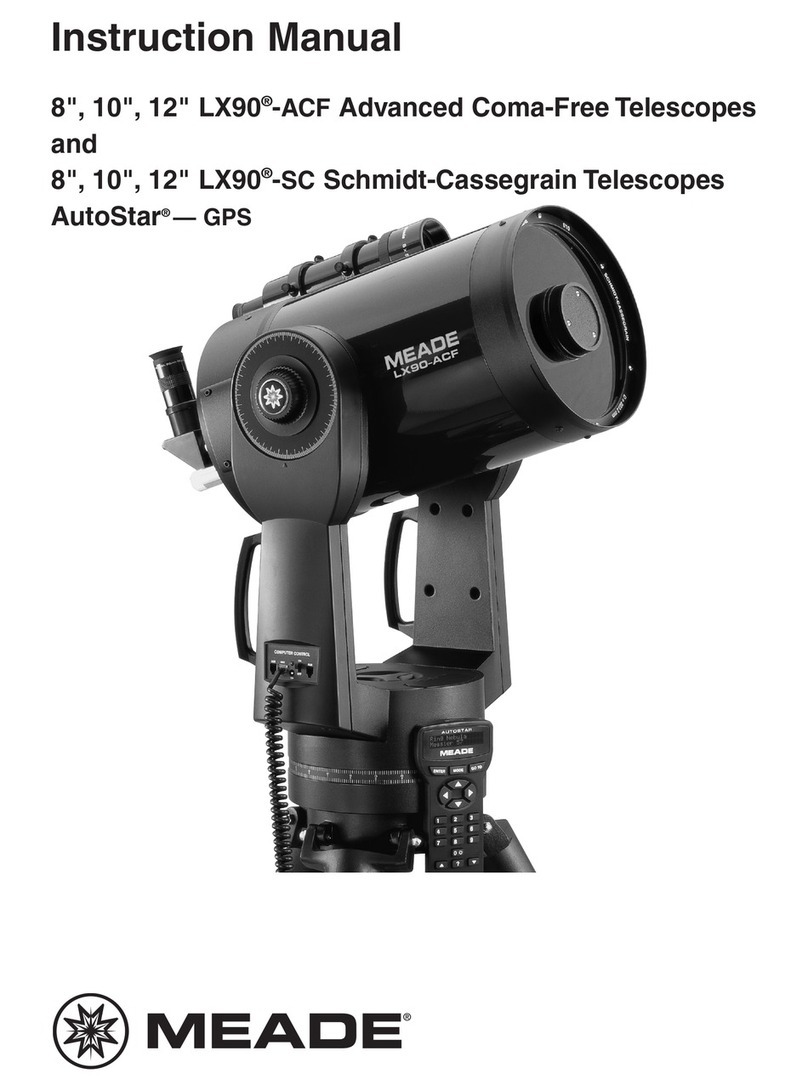
Meade 2080/LX6 Wiring diagram

Meade

Meade 2080/LX6 Wiring diagram

Meade 80EQ-AR User manual

Meade

Meade 80EQ-AR User manual

Meade 4500 User manual

Meade

Meade 4500 User manual

Meade 6600 User manual

Meade

Meade 6600 User manual

Meade Coronado SolarMax III 70 User manual

Meade

Meade Coronado SolarMax III 70 User manual

Meade LS6 User manual

Meade

Meade LS6 User manual

Meade Polaris 60EQ-D User manual

Meade

Meade Polaris 60EQ-D User manual

Meade LX80 User manual

Meade

Meade LX80 User manual

Meade LX200 CLASSIC User manual

Meade

Meade LX200 CLASSIC User manual

Meade Infinity 76 User manual

Meade

Meade Infinity 76 User manual

Meade LT ACF Series User manual

Meade

Meade LT ACF Series User manual

Meade LX200 CLASSIC User manual

Meade

Meade LX200 CLASSIC User manual

Meade 10" & 12.5" Starfinder User manual

Meade

Meade 10" & 12.5" Starfinder User manual

Meade 114 EQ-DS User manual

Meade

Meade 114 EQ-DS User manual

Meade LT ACF Series User manual

Meade

Meade LT ACF Series User manual

Meade Starfinder 16 User manual

Meade

Meade Starfinder 16 User manual

Meade RB-60 User manual

Meade

Meade RB-60 User manual

Meade 395 User manual

Meade

Meade 395 User manual

Meade ETX-70EC User manual

Meade

Meade ETX-70EC User manual

Meade AstroFinder 60 User manual

Meade

Meade AstroFinder 60 User manual

Meade Infinity AZ 80 User manual

Meade

Meade Infinity AZ 80 User manual

Popular Telescope manuals by other brands

Explore One STAR50APP instruction manual

Explore One

Explore One STAR50APP instruction manual

Celestron TRAVEL SCOPE 70 DX Quick setup guide

Celestron

Celestron TRAVEL SCOPE 70 DX Quick setup guide

Celestron NexStar 8 instruction manual

Celestron

Celestron NexStar 8 instruction manual

Orion Premium 102mm f/7.0 ED Refractor instruction manual

Orion

Orion Premium 102mm f/7.0 ED Refractor instruction manual

Celestron StarHopper 10 instruction manual

Celestron

Celestron StarHopper 10 instruction manual

Celestron C10-N Instruction manual addendum

Celestron

Celestron C10-N Instruction manual addendum

ORION TELESCOPES & BINOCULARS StarSeeker 130 II instruction manual

ORION TELESCOPES & BINOCULARS

ORION TELESCOPES & BINOCULARS StarSeeker 130 II instruction manual

Vixen Starbook-S user guide

Vixen

Vixen Starbook-S user guide

Orion SkyView 4.5" instruction manual

Orion

Orion SkyView 4.5" instruction manual

Celestron StarSense Explorer DOB instruction manual

Celestron

Celestron StarSense Explorer DOB instruction manual

National Geographic 50/360 operating instructions

National Geographic

National Geographic 50/360 operating instructions

Orion 7382 manual

Orion

Orion 7382 manual

National Geographic CF700mm manual

National Geographic

National Geographic CF700mm manual

Orion OBSERVER 70MM AZ manual

Orion

Orion OBSERVER 70MM AZ manual

iOptron Solar 60 instruction manual

iOptron

iOptron Solar 60 instruction manual

ORION TELESCOPES & BINOCULARS EON 10383 instruction manual

ORION TELESCOPES & BINOCULARS

ORION TELESCOPES & BINOCULARS EON 10383 instruction manual

TAS 30-050312 owner's manual

TAS

TAS 30-050312 owner's manual

Barska 60050 Starwatcher manual

Barska

Barska 60050 Starwatcher manual

manuals.online logo
manuals.online logoBrands
  • About & Mission
  • Contact us
  • Privacy Policy
  • Terms and Conditions

Copyright 2025 Manuals.Online. All Rights Reserved.