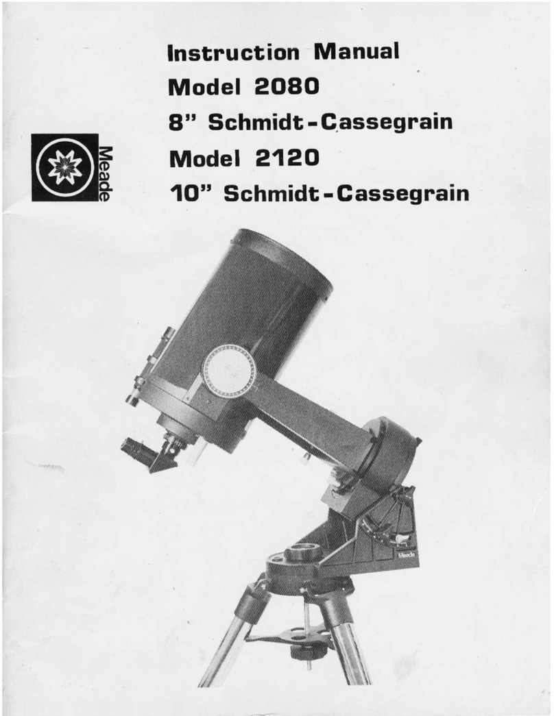
Meade 2080 User manual

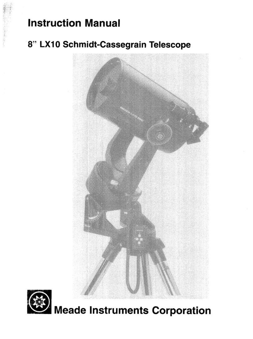
Instruction Manual
Model 20BO
B" Schmidt -Cassegrain
Model 2120
10" Schmid~ -- Cassegrain

CONTENTS
Introduction 5
The Basic Model 2080 Telescope: Standard Equipment 5
The Basic Model 2120 Telescope: Standard Equipment 6
Setting Up the Model 2080 6
Assembly and Set-up of the Model 2120 8
Telescope Op~ration: Your First Observations 10
Focusing 12
Magnifications 12
Viewfinder: Model 2080 15
Viewfinder: Model 2120 16
Field Tripod 17
Equatorial Wedge 20
Mounting the Telescope onto the Wedge 23
Celestial Coordinates 24
Lining Up with the Celestial Pole 25
Precise Polar Alignment . 28
Polar Alignment at Low Latitudes 30
Electric Motor Drive 30
Setting Circles _31
Observing with the Telescope 32
Optional Accessories and Systems
Eyepieces (l~flO.D.) 34
Eyepieces (2" O.D.) 34
Barlow Lenses 34
2" Diagonal Mirror 35
Thread-in Color Filters 35
Series -6 Color Filters 37
Erecting Prism 39
8 x 50mm Right-Angle Viewfinder for Model~ 2080 39
Nebular Filters 39
Solar Filters 40
Wide-Field Adapter System (WFAS) 41
Dew Shield 41
Accessory Shelf 42
Altazimuth Adapter 42
Photographic Accessories
T-Adapter 44
Tele-Extender 47
Guided Astrophotography 48
Piggyback Camera Bracket 49
Off-Axis Guider 50
Telecompressor- 51
Tube Balance Weight System 52
Cleaning the Optics 52
Alignment (Collimation) of the Optical System 54
Dewing of the Correcting Plate 56
Adjusting the Right-Ascension Lock 57
Adjusting the Declination Lock 57
A Note on the "Flashlight" Test 58
Factory Servicing and Repairs 58
Basic Specifications: Model 2080 58
Basic Specifications: Model 2120 60
Optical Reference Information 61

NOTE
Instructions for the use of the following optional
accessories and systems are not included in this
manual, but are shipped with the respective items:
Table Tripod for Model 2080
Model 46 VariGuide Dual-Axis Drive Corrector
Models 2047, 2048 4" Schmidt-Cassegrain Photo-Guide
Telescopes
Models 2066, 2068 4" f/2.64 Schmidt Cameras
Models 41 and 43 R.A. Drive Correctors
THE SYSTEM 2000 SCHMIm:cASSEGAAlN OPTICAL SYSTEM
(Diagram not to scale.)
F
(2)
In the Schmidt-Cassegrain design of the Meade &-inch
Model 2080 shown. tight enters from the right. passes
through a thin lens with 2-stded aspheric correction (1)
rcorrecting plate1. proceeds to a spherical primary (2)
and then to a convex aspheric secondary mirror (3). The
convex secondary mirror multiplies the effective focal
length of the primary mirror and results in a focus at F.
with light passing through a central perforation in the
primary mirror.
The 8-inch Mode12080 telescope includes an over-
size 8.25-inch diameter primary mirror. yielding a fulty it.
luminated fieId-of-view significantly wider than is possible
with a standard 8-inch diameter primary. Because the
Schmidt correcting plate near its edge acts. in effect. as a
negative lens. ighI impinging near the circurnferenceof the
correcting plate is lost unless the primary mirror size c0m-
pensates for this light diverging from the corrector. (Note in
the diagram lhallight rays A1and A2would be lost except
for the oversize primary mirror.) In fact. the oversize primary
of the Model 2080 results in about 6 percent more &ght
reaching the focal surface of the telescope. The optical
design of the 4. Model 2040 is almost identical but does not
include an oversize primary. since the effect in this case is
small.

-5-
MEADE MODELS 2080 and 2120
8" and 10" SCHMIDT-CASSEGRAIN TELESCOPES
PRECAUTIONARY WARNING! Be .sure to read this manual, or at
minimum the introductory assembly and operational proced-
ures contained herein (pages 5 to 15) before attempting to
use your Model 2080 or 2120.
INTRODUCTION
The Meade Model 2080 8" Schmidt-Cassegrain Telescope and
Model 2120 10" Schmidt-Cassegrain Telescope are.instruments
of advanced mirror-lens design for astronomical and terres-
trial applications. Optically and mechanically, the Models
2080 and 2120 are perhaps the most sophisticated and precisely-
manufactured telescopes ever made available to the serious
amateur. The Mode.ls 2080 and 2120 enable the visual astronomer
to reach out for detailed observations of the Solar System
(the planets: Jupiter, Saturn, Mars) and beyond to distant
nebulae, star clusters, galaxies. The astrophotographer will
find a virtually limitless range of possibilities since, with
the precision Meade worm-gear motor .drive system, long ex-
posure guided photography becomes not a distant goal, but
an achievable reality. The capabilities of the instrument
are essentially ~imited not by the telescope, but by the
acquired skills of the observer and photographer. Do take
the time to read this manual thoroughly, so that you will
be fully acquainted with the many important features of the
telescope, as well as with the auxiliary equipment arid
accessories.available for advanced applications.
The Models 2080 and 2120 are, with the exceptions of a few
assembly operations and features, almost identical operational-
ly. Most stapdard ~nd optional accessories are interchange-
able between the two telescopes. As such, the instructions
in this manual generally apply to both telesco~es; when ex-
ceptions to this rule occur, they are clearly pointed out in
the following.
THE BASIC MODEL 2080 TELESCOPE: STANDARD EQUIPMENT
The Meade Model 2080 Telescope is packed in a urethane-foam-
lined carrying case.. If the telescope was shipped to you,
this carrying case was in turn placed in a thick-wall corru-
gated carton, lined on all 6 sides with styrofoam sheets.
(NOTE: We recommend that you keep all packing materials
for either the Model 2080 or Model 2120; if it is ever
;..:,-~.

-6-
necessary for you to return your telescope to the Meade
factory for servicing, these materials will help to assure
that no shipping dam~ge will occur.)
Packed in the carrying case are the complete basic Model
20aO, consisting of the a" Schmidt-Cassegrain optical
tube assembly and fork mount. Accessories included as
standard equipment are normally also packed within the
carrying case.
The Model 20aO (or foreign Model 20aOF) includes the follow-
ing standard equipment:
a."Schmidt-Cassegrain optical tube
and Fork Mount with Motor Drive
2 Eyepieces (l~" O.D.): MA 9mm (222X)
MA 25mm (aOX)
Eyepiece-Holder (l~'.)
.Diagonal Prism (1\,") ~~
6 x 30mm viewfinder witti rac~~t .
.Dust Covers: One for rear-c~ pen1ng
~~One for correcting plate
3-Knob sc~ for attach~ng Model 2080
T to Equator1alWedge
Hex wrench set (3 pes.)
Carrying Case
Power Cord
THE BASIC MODEL 2120 TELESCOPE: STANDARD EQUIPMENT
The Model 2120 is packed for shipment in 2 cartons: Carton
No. 1 includes the complete 10'. Optical Tube Assembly with
fork arms attached; Carton No. 2 includes the Motor Drive
base (and 4 bolts for attachment of the Motor Drive base
to the fork arms), viewfinder, viewfindex bracket, accessories,
power cord, and hardware package, all packed within the
carrying case.
The Model 2120 (or foreign Model 2l20F) includes the following
standard equipment:
10" Schmidt-Cassegrain optical tube and Fork
Mount with Motor Drive
2 Eyepieces (l~" O.D.): MA 9mrn (27aX)
MA 2Smm (lOOX)
Eyepiece-Holder (l~n)
Diagonal pr ism (l~'.)
a x 50mm viewfinder with bracket
Dust Covers: One for rear-cell opening
One for correcting plate
3-Socket capscrews for attaching Model 2120
Telescope to the Equatorial Wedge

-7-
Fig. 1: Meade Models 2080 and 2120. (1) Viewfinder;
(2) Declination Lock; (3) Declination Setting Circle;
(4) Declination Slow-Motion Control; (5) R.A. Lock;
(6) R.A. Slow-Motion Control; (7) Eyepiece-Holder;
(8) Diagonal Prism; (9) Eyepiece; (10) Focus Knob;
(II) Drive Base; (12) R.A. Setting Circle.

-8-
Hex wrench set (5 pes.)
Carrying -C~se
Power Cord
- - - .
Note to For.eignUsers:'S" and 10" Schmidt-Cassegrain...models
supplied to countries'ou'tside-thet,J.S.A.;: -are identical in
all respects.to the telescopes offered domestically,-except
that the powe.rcord and-the'electrica1'connector (located
in the base 'ofthe.telescope fork mount) are different. The
power cord'plugs directly into th~ base of the .telescope
.(see "The Motor Drive"), but you -'may-have to s1ipply your own
adapter in order-.-to 'plug into your loca.l. electric~l outlet.
In this case be sure that the adapter is of a "3-prong" type
so that the .telescope is'proper ly .grounded'a-t. all times
during operation. .-
SETTING UP THE-MODEL 2080
The basic-Model 2080. telescope is shipped as a completely
assembled ins.trument~-For safety in shipment the 6 x 30mm
Viewfinder is_packed separately. (See "The Viewfinder,."
below.) After removing the telescope from j,ts shipping
carton and carrying case, famili~rize yourself with the
various control~,and accessories; see Fig. .1.
The eyepiece-holder threads directly onto the rear-cell
thread of the Models 20S0 and 2120. The diagonal prism slides
into the eyepiece-holder and in turn accepts either of the
supplied l~" O.D. eyepieces. For astronomica-l observations
the diagonal prism generally provides a more comfortable
right-angle viewing position. Alternately, an' eyepiece may
be inserted directly into the Eyepiece-Holder for straight-
through observations.- Note in this case, however, that
the image will app~a'r inverted and reversed left-for-right.
with the Diagonal Prism, telescopic images appear correctly
oriented up-and-down, but still reversed left-for-right. For
terrestrial applications,: where a,fullycorrected image
orientation is desired,'-both up-and-down and left-for-right,
the optional =1924 Erecting Prism :(l~" O.D.) should be ordered
separately._ (See the Meade General' Catalog for details.)
Eyepieces and the Diagonal Prism are held in their respec-
tive places on- the telescope by a.moderate tightening of the
thumb-screws on the Diagonal Prism and Eyepiece-Holder.
ASSEMBLY AND SET-UP OF THE MODEL 2120
The basic Model 2120 telescope is shipped with the optical
tube assembly (with fork ar~s attached) in one carton,
and with the motor drive base in a separate carton. The
only assembly operations required are the following:

-9-
1. Attaching the fork arms to the motor drive base.
2. Attaching the viewfinder and viewfinder bracket
to the optical tube.
'. :
To -remove-theoptical tube-from the shipping carton, (1) lift
off the lid of the carton; (2) place the carton on end with
the eyepiece-end- at the bottom; (3) remove packing material
from the top of the carton; (4) pull the tube assembly
toward you and out-of the carton.
To attach the fork arms'to the motor drive base: (1) Place
the optical tube flat on a carpeted-floor. (2) Remove
the threaded metal rod that has been used to tie the fork
arms-together for safety in shipment (this rod may be set
as.idefor re-use;
-in case of future commercial shipment).
:(3) Remove the, 4 bolts (2 on. each side) from ~he flat
sides of the motor d~ive base (these bolts will be used to
attach"the fork arms to the drive base). .(4) Note that the
flat surfaces at the bottoms of the fork arms are numbered;
these~numbers will aid you in joining the correct.fork arm
to the -correct side of the drive base. Thus, join the No. 1
fork_'arm to.the No. I-side of the drive base, and the No.2
'fOrk arm to the No.2-side of the drive base. (5) Thr~ad
-in:,by hand the 4 attachingbolts (2 througheach fork arm)
through'the fork arms and into the drive base, to get the
bolts,well started. Then use the long-arm of the hex wrench
,pr.ovided,to screw in the bolts the rest of the way. For
final tightening use the short arm of the hex wrench. These
bolts should be tightened to a good firm tightness. Once
attached, the fork arms may be left permanently attached to
the drive base and the complete optical tube/fork mount/drive
base system may be stored as an assembled unit in the carry-
ing case. '(The only exception to this statement is in"ship-
ment of the telescope by commercial freight carrier, in
which case the drive base should be removed, and the telescope
shipped exactly in the'manner in which you received it.)
To store.your telescope in its carrying case you may find the
following procedure most convenient:
1. Stand the case on end with the lid open.
2. Place -the telescope inside the case wi:ththe
flat side of the drive base at bottom.
3. If the 8 x 50 viewfinder (see liTheViewfin~er:
Model 2120", below.) is mounted on the tele-
s90pe you will note that it will prohibit your
closing the lid of the case. Therefore,
'4. Push the fork arm on the side of the viewfinder
towards the back (or bottom) of the case. You
will note that the viewfinder is now far enough
back so that the-lid, when closed, will not touch
the viewfinder.

- ----
-- --
-10-
5. Tuck in the 2 pieces gf blue foam (provided with
shipment) along .the base of each fork arm so that
the instrument will not move inside the case. You
can now store the instrument or place it in your
car for transport to an observing site.
CAUTION
DO'NOT ATTEMPT TO TURN THE FOCUSER KNOB OF THE OPTICAL TUBE
UNTIL YOU HAVE READ THIS NOTICE!
Next to the base of the focuse~ knob you will see a red-
colored slotted bolt head. This bolt is used only for safety
in shipment. Remove this bolt before attempting to turn the
focuser knob. In-its place insert the rubber plug provided
as a dust protector (this rubber plug is included with your
hardware package).
Your.focuser is now operational.
WARNING! The Mode~ 2120 should never be commercially shipped
without this red~colored-head bolt secured in place. .This is
essential during commercial transport where rough handling
may occur. For your:personal transport and storage you will
never need to use this bolt again.
TO COMMERCIALLY RE-SHIP THE MODEL 2120 BE SURE TO FOLLOW
THIS PROCEDURE:
1. Turn the focuser knob clockwise continuously
until.it stops. This will bring the primary
mirror all.the way back in the tube.
2. Remove the rubber plug and insert the red-headed
bolt. Thread it in to a firm snug feel.~ Do not
over-tighten. (If you have misplaced the 'red-
head bolt you may use any other bolt that is
~-20xl" long).
Please note that commercial shipment of the Model 2120 tele-
scope without this safety bolt in place is done at owner IS
risk and your freight insurance may be voided if shipping
damage results.
TELESCOPE OPERATION:
MODEL 2080 OR 2120
!
YOUR FIRST OBSERVATIONS THROUGH THE
with the telescope standing upright on its motor drive
base, as shown in -Fig. 1, and with the Diagonal Prism/and
MA 25mm eyepiece in place, you are ready to make observations
through the telescope. (Because the viewfinder has not yet
been attached to the telescope, be sure to use the MA 25mm
eyepiece, which yields 80 power on the Model 2080 (IOOX on
the Model 2120), and not the higher power MA 9mm eyepiece.

-11-
Even without the-viewfinder, terrestrial objects will be
fairly easy to locate and center in the telescope's field
of view with the lower-power eyepiece, simply by "gun-
sighting" along the side of the main telescope tube.)
IMPORTANT NOTE: NEVER POINT THE TELESCOPE DIRECTLY AT THE
SUN, OR ATTEMPT TO OBSERVE.THE SUN, EITHER THROUGH THE
MAIN TELESCOPE.OR THE VIEWFINDER, WITHOUT PROPER PROFESSION-
AL EQUIPMENT. INSTANT AND IRREVERSIBLEDAMAGE TO YOUR EYE
MAY OTHERWISE RESULT! (SEE "SOLAR FILTERS" IN THIS MANUAL.)
By unlocking the.R.A. lock (5), Fig. 1, the te"lescope may
be turned rapidly through wide angles in Right Ascension
(R.A.). (The reason for the terminology."Right Ascension"
and its complementary term "Declination" will be made clear
further on in this manual. For now, "Right Ascension" I
simply means "h.orizontal" and "Declination" means "vertical.")
Fine-adjustmen.ts inR.A-. are made by turning the R.A. control
knob (6), Fig. 1, while the R.A. lock is in the "unlocked"
position.
DO NOT ATTEMPT TO MOVE THE TELESCOPE MANUALLY IN A HORIZONTAL
DIRECTION WHEN THE R.A. LOCK IS IN THE "LOCKED" POSITI'ON.
The R.A. control knob may be turned, if desired, with the
R.A. IO.ckin a "partially locked" position. In this way a
comfortable "drag" in R.A. is created. But do not attempt
to operate the R.A. control knob with the telescope fully
locked in R.A., as such operation may result in damage to
the internal gear system.
-Releasing the Declination lock (2), Fig. 1, permits sweep-
ingthe telescope rapidly through wide angles in Declination.
DO NOT ATTEMPT TO MOVE THE TELESCOPE.MANUALLY IN A VERTICAL
-DIRECTIONWHENTHE DECLINATION LOCK IS IN THE "LOCKED"
POSITION.
To use the Declination fine-adjust, or slow-motion, control,
lock the telescope in Declination using the Declination lock
(2), Fig. 1, and turn the Declination slow-motion knob (4).
NOTE THAT THIS DECLINATION SLOW-MOTION CONTROL HAS A F.IXED
TRAVEL LENGTH, LIMITED BY THE MOTION OF A TANGENT ARM
(LOCATED INSIDE THE FORK TINE). DO NOT FORCE THE DECLINATION
SLOW-MOTION KNOB WHEN THE TANGENT ARM HAS REACHED THE END
OF ITS T.RAVEL. IN THIS CASE TURN THE DEC. KNOB TO RETURN THE
.TANGENT ARM TO THE MID-POINT IN ITS TRAVEL RANGE, UNLOCK
THE DECLINATION LOCK, AND RE-CENTER THE TELESCOPE TUBE MANUALLY.
With above mechanical .operations in mind, select an easy-to-
find terrestrial object as your first telescope subject--for
example, 'ahouse or building perhaps one-half mile distant.

-12-
Unlock the Dec. lock (2), Fig. 1, and R.A. lock (5),
center the ~bject in the telescopic field of view, and then
re-lock the Dec. and R.A~ locks. Precise image centering is
accomplished by using the Dec. and R.A. slow motion controls,
(4 ) and (6) .
FOCUSING
The focusing knob (10), Fig. 1, is located at the "4 o'clock"
position as you face the rear cell of the telescope. Focus-
ing is accomplished internally by a precise motion of the
telescope primary mirror, so that, as you turn the focus knob
there are no externally moving parts.
Focusing the telescope from its nearest possible focus point
(on an object about 25 ft. away with the Model 2080, or
about SO ft. with the Model 2120) to an object at infinity
requires a fairly large number of rotations of the focus knob.
The focuser is designed to provide an extremely sensitive
means of bringing an object into precise, sharp focus. After
a specific object has been brought into focus, closer ob-
jects require turning the focus knob clockwise; more distant
objects require turning the focus knob counterclockwise.
It is possible that you may notice a slight shifting of
the image as you focus, particularly at high powers. This
image shift is caused by very small lateral motions of the
primary mirror as it moves toward or away from the secondary
mirror during the focusing procedure.
MAGNIFICATIONS
The magnification, or power, of the telescope depends on
two optical characteristics: the focal length of the main
telescope and the focal length of the eyepiece used during
a particular observation. The focal length of the main Model
2080 telescope is fixed at 2000mmi the focal length of the
main Model 2120 telescope is fixed at 2500mm. To calculate
the power in use with a particular eyepiece, divide the .
focal length of the eyepiece into the focal length of the
main telescope. For example, using the MA 25mm eyepiece
supplied with the Model 2080, the power is calculated as
follows:
Power =2000mm =80X
25mm
Similarly, with the MA 9mm eyepiece, a magnifying pow~r
of 2000mm/9mm, or 222X, results. The ~of eyepiece
(whether "MA" Modified Achromatic, "OR" Orthoscopic, "ER"
Erfle, etc.) has no bearing on magnifying power, but does

-13-
affect such optical characteristics as field of view,
flatness of field, and color correction.
The table below lists the operating powers of ~he Models
2080 and.2120 telescopes, when the in,strumentis used with
eyepieces of varying focal lengths.
Eyepiece
Focal .Length
40mm
32mm
28mm
25mm
20mm
l8mrn
l6.8mm
lS.5mrn
12.4mm
10.5riun
9rnm
7mrn
6rnm
4rnrn
Magnifying Power
When Used with Model 2080 Magnifying Power
When Used with Model 2120
sox
63X
7lX
80X
lOOX
lllX
ll9X
129X
l61X
190X
222X
286X
333X
SOOX
63X
78X
89X
lOOX
12SX
l39X
149X
161X
202X
238X
27'8X
357X
4l7X
625X
Because of certain characteristics of the human eye (in
particular, eye pupil diameter) and because of optical
considerations inherent in the design of a telescope, there
exist minimum practical power levels also~ Generally

-14-
Fiq. 2A: 6 x 30mm Viewfinder
for Model 2080. (1) Mounting
Screw; (2) Objective Lens Cell;
(3) Knurled Collar; (4) Colli-
mation Screw; (5) Eyepiece.
Fiq. 3: Field Tripod. (1) Head;
(2) Threaded Rod; (3) Tension
Knob; (4) Spreader Bar; (5) Lock
Knobs; (6) Extension Strut;
(7) Hub.
Fiq. 2B: 8 x 50mm View-
finder for Model 2120.
(1) Mounting Screw; (2)
Objective Lens Cell: (3)
Collimation Screws:
(4) Focuser; (5) Eyepiece.
Fiq. 4: Field Tripod
(collapsed)

-15-
speaking, the lowest usable power is approximately 4X per
inch of telescope aperture, or about 32X in the case of the
8" aperture Model 2080, about 40X in the case of the 10"
Model 2120.' During the daytime, when human eye pupil diameter
is reduced, the minimum practical power with the Model 2080
is increased .to about 60X, or to about 75X with the Model
2120; .powerslower than this level should be avoided during
daytime observations. A reasonable.magnification range for
daytime terrestrial observations through the Model 2080 is
from about SOX to 190Xi through the Model 2120, from about
100X to 200X.
Accessories are available both to increase and decrease the
operating eyepiece power of the telescope. See the sections
of this manual on "The Barlow Lens" and "Wide Field Adapter
S.ys tem. "
THE VIEWFINDER: MODEL 2080
The standard 6 x 30mm Viewfinder is shipped in its mounting
bracket with each Model 2080 telescope. Mounting screws for
-theviewfinder bracket have been threaded into the top of
the main telescope's rear cell, at the hole-positions where
the viewfinder bracket will be seated. S~e Fig. 2A.
{
I
\
!
!.
j
To attach the viewfinder, remove the 2 viewfinder mounting
screws from the rear-cell, using one of the he~ wrenches
provided with the telescope; place the viewfinder-with-
bracket over these mounting holes, and then replace the 2
mounting sc.rewsto securely attach the viewfinder bracket
to the rear-cell. Tightening these mounting screws to a
"firm feel" is sufficient; avoid over-tightening, which
might cause the rear-cell threads to strip.
WARNING: Never use set 'screws on any part of the optical
tube assembly, except those factory-supplied set screws
included with the basic telescope or with optional acces-
sories.. Longer, ~on-standard set screws may protrude too
far into the optical tube and cause serious damage to the
primary mirror.
The 6 x 30mm Viewfinder has been factory pre-focused at
infinity. Should this focusing need adjustment for your
eyes, loosen the knurled collar at the objective lens-end
of the viewfinder (see (3), Fig. 2A), enabling rotation
of the objective lens cell, forward or backward, for precise
focusing. Then tighten down the knurled collar against the
objective lens cell, to lock the focus in place. Note that
no focusing is possible, or necessary, at the eyepiece-end
of the viewfinder.

-16-
The optional 6 x 30mm Right-Ang~e Viewfinder fits into the
same mounting bracket as the standard 6 x 30mm Viewfinder.
To insert the"6 x 30mm Right-Angle finder into the bracket,
first unthread the objective lens cell and knurled ring from
the finder, insert the finder tube into the bracket, and re-
attach the knurled ring and objective -lenscell. Focusing
may be fixed following the same procedure outlined in the
preceding paragraph.
The viewfinder will require alignment, or collimation, tp
the main telescope. using the 25mm eyepiece, point the main
telescope at some easy-to-find land object (e.g., the top of
a telephone pole or corner of a building) at least 200 yards
distant. Center a well-defined object in the main telescope.
Then, using one of the hex wrenches provided, tighten or
loosen, as appropriate, the viewfinder's 3 collimation
screws (see (4), Fig. 2A) until the crosshairs of the view-
finder are precisely centered on the object already centered
in the main telescope. With this collimation accomplished,
objects located first in the wide-field viewfinder will then
be centered in the main telescope's field of view.
Once attached, the viewfinder may be le"ftpermanently mounted
onto the telescope's- rear-cell~ The viewfinder need not be
removed when storing the telescope in its carrying case.
THE VIEWFINDER: MODEL 2120
Each Model 2120 is supplied as standard equipment with an
8.x SOmrnstraight-through viewfinder. The bracket for this
viewfinder is packed separately from the finder itself, and
6 nylon thumbscrews for collimation are pre-threaded into
the viewfinder bracket. Mounting screws for attachment of
the finder bracket to the main telescope have been threaded
into the top of the main telescope's rear cell, at the hole
positions where the viewfinder bracket will be seated. See
Fig. 2B.
To attach the viewfinder, remove the 2 viewfinder mounting
screws from the rear-cell, using one of the hex wrenches
provided with the telescope; place the viewfinder-with-
bracket over these mounting holes, and then rep1ace the 2
mounting screws to securely attach the viewfinder bracket
to the rear-cell. Tightening these mounting screws to a
"firm feel" is sufficient; avoid over--tightening, which might
cause the rear-cell threads to strip.
WARNING: Never -use set screws on any part of the optical
tube assembly, except those factory-supplied set screws
included with the basic telescope or with optional accessories.
Longer, non-standard set screws may protrude too far into
the optical tube and cause serious damage to the primary
mirror.
Focusing the finder is accomplished with the helicoid mech-
anism located near the finder's eyepiece. Note: if the

-17-
eyepiece is ever removed from the finder, be careful not
to touch in any way the crosshairs of the eyepiece, which
are exposed at the barrel-end of the eyepiece!
Collimation, or alignment, of the Model 2120's viewfinder
is accomplished in the same way as described above for the
Model 2080, except.that no ..hexwrench is required: simply
turn the 6 nylon thumbscrews to achi~ve correct alignment.
Once attached, the viewfinder may be left permanently mount-
ed onto the telescope's rear-cell: the viewfinder need not
be removed when storing the telescope in its carrying case,
if the procedure described above (see "Assembly and Set-up.
of the Model 2l20~')1s employed.
THE FIELD TRIPOD
.\.
The.Field Tr'ipods for the Meade Models 2080 and 2120 tele-
scopes are supplied as completely assembled units, except for
6 lock-knobs (2 knobs for each of the 3 tripod legs) used to
adjust the h~igbt'of the tripod. These knobs are packed
separately'forsa:fetyin shipment. .
Note that, except for ,6 additional threaded holes located
on the top surface of the Model 2120's Field Tripod, the
Field Tripods for Models 2080 and 2120 are identical. These
threaded holes serve as additional mounting points when the
Equatorial Wedge of the Model 2120 is attached to the Field
Tripod. This function will be made clear below.
For terrestrial observations the base of the Model 2080's
fork mount may be attached to the Field Tripod, using the
optional Altazimuth Adapter. (Because of the additional
weight of the Model 2120, we do not normally recommend use
of the Model 2120 with the Altazimuth Adapter.) The Model
2080 telescope in .this way is mounted in an "altazimuth"
("a1titude-azimuth,"or "vertical-horizontal") format, ideal
for non-astronomical applications. The tele.scope in this
set-up moves along.vertical and horizontal axes, correspond-
ing respectively to the Declination and Right Ascension axes
in.an astronomical observing mode. _~he telescope may of
course be used for.'as.tronomicalobservations when set-up in
the altazimuth mode, but.the electric motor drive will in
this case be non-functional from a practical point of view.
Alternately, the Field Tripod of the Model 2080 or 2120 is
normally used in conjunction with the appropriate Equatorial
Wedge (see next. .section) .for serious astronomical applica-
tions. The:"Equatorial Wedge permits alignment of the tele-
scope's Polar Axis with -th~Celestial Pole, so that the
electric motor. drive becomes operational.

-18-
Fiq. 5: The Model 2080 Mounted on Equatorial
Wedge and Field Tripod.
Fig. 6: Field Tripod Head. (1) Threaded
Holes (Model 2120 Tripods only); (2) Threaded
Rod.

-19-
After removing the Field Tripod from its shipping carton,
stand the tripod vertically, with the tripod feet down,
and ~ith the tripod still fully cOllapsed. Grasp two of
the tripod legs 'and, with the full weight of the-tripod
on the third leg, gently pull the legs apart to a fully
open position.
Thread in the'6 lock-knobs (2 on each tripod leg) near the
foot of each tripod leg. Refer to Fig. 3. These lock-
knobs are ,used to fix the height of the inner, extendable
tripod leg 'sections. ~: "Firm feel" tightening is
sufficient; over-tightening may result in stripping of the,
knob threads,_
Unthr.ead the Tension 'Knob ,(see (3), Fig. 3) sufficiently
,to allow the 'Spre~der-Bar (4) to rotate. The Spreader Bar
should be rota.ted 'about 600 from its shipping position
unti~>~he 3 -atms of the Spreader Bar are lined up with the
3 tripod legs. Then, turn the Threaded Rod (2) so that
.,..' .-abou't.l~" of its length protrudes up through the Head (1)
'of the Field Tripod.
Underneath the Head (1) of the Field Tripod is a hex lock-
nut, which should be.tightened to fix the position of the
Threaded Rod.
Re-tighten the Tension. Knob (3). Firm tightening of the
Tension Knob is sufficient to result in rigid positioning
'of the .tripod legs. It is not necessary to'use extreme force
~n t~ghtening t,his,knob.
The Field Tripod is. now ready to accept the Equatorial-Wedge.
To vary the ,tripod height, loosen the 6 lock-knobs and
'slide the 3 inner tripod leg sections out to the desired
height.
To collapse the tripod for storage, follow these steps:
(1) Loosen the Tension Knob (see (3), Fig. 3)
sufficiently to,allow the Spreader Bar (4) to
rotate 600 from its assembled position, so
that one Spreader Bar arm is located between
€ach adjacent pair of tripod,legs.
(2) Leave'the Tension Knob near the bottom end of
the Threaded Rod (2), with the Spreader Bar
resting on the Tension Knob.
(3) At the base -of the tripod is a 3-vane extension
strut system, with a circular hub at its center.
To collapse the tripod, grasp the tripod head
(1) with one hand, and, with the other hand,

-20-
pull directly "up" on the central hub of the
extension strut system. This operation will
cause the tripod legs to move inward to a
coll'apsed posi tion-. .
PRECAUTIONARY NOTES
(1) If the tripod does not seem to extend or col-
lapse easi.ly,do not force the tripod legs in
or out. By following the instructions above
the tripod will function properly, but if you
are unclear on the proper procedure, forcing
the tripod into an incorrect position may damage
the extension strut system.
(2) Do not overtighten the 6 lock-knobs used to fix
the inner tripod leg sections at various heights.
"Firm feel" tightening is sufficient.
THE EQUATORIAL WEDGE
The Equatorial Wedge permits use of the Model 2080 or 2120
telescope in an astronomical or "equatorial" mode. The
wedge fits onto the Field Tripod, described above, and
accepts the base of the Model 2080 or 2120 fork mount. See
Fig. 5.
NOTE: The Meade Equatorial Wedge is designed solely for
use in"conjunction with the Meade Field Tripod. The wedge
should never be used without the Field Tripod, e.g. by
placing the wedge alone on a table top, and then mounting
the telescope on the wedge. The Model 2080 or 2120 tele-
scope, placed onto the Equatorial Wedge alone, without the
Field Tripod attached to the wedge, may become' seriously
imbalanced, to the point where the telescope may actually
tip over.
Except for the tilt plate (Fig. 8) appropriate to each
model, the Equatorial Wedges for the Models 2080 and 2120-
are otherwise identical.
The Equatorial Wedges appropriate to either the Model 2080
or 2120 are of modern d~sign, with several important features
incorporated to simplify and facilitate telescope operation.
After using the wedge for your telescope, you'will find that
the functional design features included are of very signifi-
cant value in routine telescope operations. Some of these
features include:
1. Attachment of the wedge to the field tripod by
means of only one manual knob. (For photographic
applications with the Model 2120 where extreme
steadiness is required, 3 additional hex-head
screws are provided.)

-21-
Fig. 7A: Equatorial Wedge for 2080.
(I) Tilt-Plate; (2) Attachment Knob;
(3) Latitude Scale; (4) Wedge Body;
(5) Tilt Angle Adjustment Knob;
(6) Fine Latitude Adjustment Mech-
anism; (7) Bubble Lev~l.
Fiq. 7B: Equatorial Wedge for 2120.
(1) Tilt-Plate; (2) Attachment Screw;
(3")Latitude Scale; (4) Wedge Body;
(5) Tilt Angle Adjustment Screw;
(6) Fine Latitude Adjustment Mech-
anism; (7) Bubble Level.
Fig. 8: Placing the Telescope
on the Wedge.
(1) Tilt-Plate.
(2) Apertu~e for Power Cord.
(3) Wedge Body-to-Tilt Plate
Attachment Knob.
(4) Tilt Angle Adjustment Knob..
(5) Knob for attaching Telescope
to Tilt-Plate.
(6) Drive Base. .
(7) Slot for Knob (5).
(8) Holes for additional a~tach-
ment knobs.
(9) Bubble Level.
(10) Manual Knob for attaching
Wedge to Field Tripod.
This manual suits for next models
1
Table of contents
Other Meade Telescope manuals

Meade
Meade RCX400 User manual

Meade
Meade pmn User manual

Meade
Meade LXD 500A User manual

Meade
Meade Adventure Scope Series User manual

Meade
Meade Coronado SolarMax III 70 User manual

Meade
Meade LX-90 User manual

Meade
Meade NG70-SM User manual

Meade
Meade NG User manual

Meade
Meade DSX User manual

Meade
Meade MAX-ACF User manual

Meade
Meade 70AZ-T User manual

Meade
Meade ETX series AutoStar User manual

Meade
Meade POLARIS SERIES User manual

Meade
Meade ETX Premier User manual

Meade
Meade ETX-70EC User manual

Meade
Meade 6600 User manual

Meade
Meade LT ACF Series User manual

Meade
Meade ETX-AT User manual

Meade
Meade AudioStar User manual

Meade
Meade TELESTAR RB-70 User manual