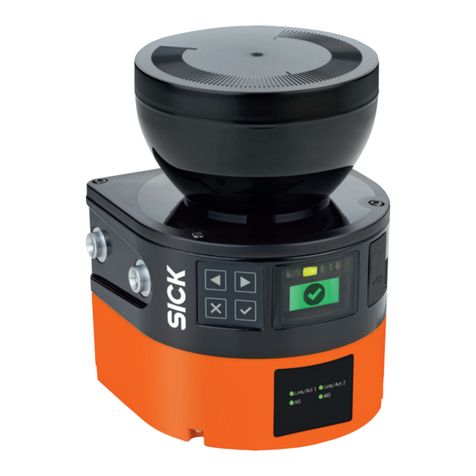
MEDA MD-6000P User manual

MEDA Co., Ltd
www.meda.com.cn
MD-6000P
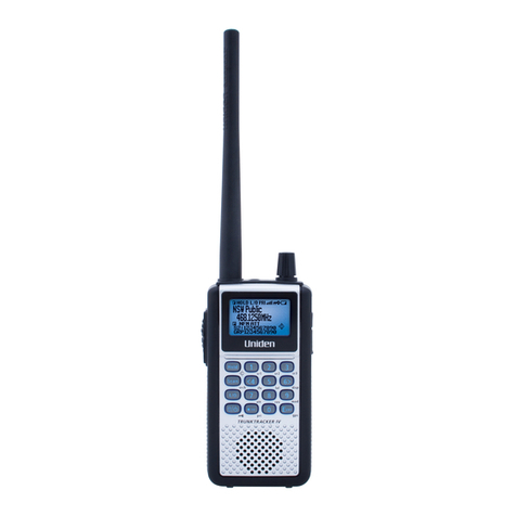
Bladder Scanner
USER MANUAL

MEDA Co., Ltd.
F2C, F3D, F4C, F5, F6C, Building C2, Xinmao Science Skill Park, Huayuan Industry
Development Area, Tianjin 300384, PEOPLE’S REPUBLIC OF CHINA
Tel: +86-22-83713808 Fax: +86-22-83713880
URL: http://www.meda.com.cn E-mail: export@meda.com.cn
Shanghai International Holding Corp. GmbH (Europe)
Eiffestrasse 80, 20537 Hamburg, GERMANY
Tel: +49-40-2513175 Fax: +49-40-255726
US Service Center: APM INC.
12 Cinnamon Court, Holmdel, NJ 07733, U.S.A.
Tel: +908-461-7750

CONTENTS
- I -
CONTENTS
FCC STATEMENT .............................................................................................................................................IV
PRECAUTIONS AND WARNINGS...................................................................................................................V
LABELS AND INDICATORS..........................................................................................................................VII
EXPLANATION OF LABELS AND SYMBOLS ON THE PACKINGBOX.............................................VIII
CHAPTER 1 INTRODUCTION.......................................................................................................................1
1.1 GENERAL DESCRIPTION ...............................................................................................................................1
1.2 MAIN FEATURES ..........................................................................................................................................1
1.3 INTENDED USE.............................................................................................................................................1
1.4 INTENDED CONDITIONS OF USE ...................................................................................................................1
1.5 CONTRAINDICATIONS...................................................................................................................................1
1.6 SOFTWARE VERSION ....................................................................................................................................1
CHAPTER 2 SPECIFICATIONS.....................................................................................................................2
2.1 WORKING CONDITIONS................................................................................................................................2
2.2 SPECIFICATIONS ...........................................................................................................................................2
2.3 SAFETY........................................................................................................................................................2
2.4 STORAGE AND TRANSPORTATION .................................................................................................................2
2.5 PRODUCT CLASSIFICATION...........................................................................................................................3
2.6 LI-ION BATTERY...........................................................................................................................................3
CHAPTER 3 INSTALLATION.........................................................................................................................4
3.1 STRUCTURE .................................................................................................................................................4
3.2 ENVIRONMENTAL REQUIREMENT.................................................................................................................6
3.3 CONNECTION ...............................................................................................................................................6
3.3.1 Charging .............................................................................................................................................6
3.3.2 Using Together with Tablet PC............................................................................................................7
CHAPTER 4 OPERATION...............................................................................................................................9
4.1 START-UPAND SHUT-DOWN..........................................................................................................................9
4.1.1 Check-up before Start-up ....................................................................................................................9
4.1.2 Start-up................................................................................................................................................9
4.1.3 Check-up before use............................................................................................................................9
4.1.4 Shut-down............................................................................................................................................9
4.1.5 Shut-down of the Tablet PC.................................................................................................................9
4.2 INTRODUCTION OF THE FUNCTION MODULE..........................................................................................10
4.2.1 Main Interface..................................................................................................................................10
4.2.2 System Parameter Setting................................................................................................................. 11
4.2.3 Patient Selection...................................................................................................................................15
4.2.4 Scanning...............................................................................................................................................16
4.2.5 Recommended Operation Procedure....................................................................................................22
4.3 OPERATION INSTRUCTIONS FOR THE JOINTLY-USED TABLET PC ..................................................................23

CONTENTS
- II -
4.3.1 Start-up and Shut-down of the Tablet PC.............................................................................................23
4.3.1.1 Check-up before Start-up ..................................................................................................................23
4.3.1.2 Start-up...........................................................................................................................................23
4.3.1.3 Check-up before use.......................................................................................................................23
4.3.1.4 Shut-down of the Tablet PC............................................................................................................23
4.3.2 Configuration of the Tablet PC and Software Installation Instructions...............................................23
4.3.3 Main Interface......................................................................................................................................24
4.3.4 Main Unit Connection..........................................................................................................................27
4.3.5 Patient Information Interface...............................................................................................................28
4.3.7 3D Scanning Mode............................................................................................................................30
4.3.8 Bladder Projection Image....................................................................................................................30
4.3.9 Save......................................................................................................................................................31
4.3.10 Case Report........................................................................................................................................31
4.3.11 Patient Case Management..................................................................................................................32
4.3.12 System Parameter Setting...................................................................................................................33
4.3.13 Name of Medical Institution...............................................................................................................34
4.3.14 Operator List......................................................................................................................................34
4.3.15 Patient List.........................................................................................................................................35
4.3.16 Pair Key.............................................................................................................................................37
4.3.17 Automatic Connection Switch ............................................................................................................37
4.3.18 Main Unit Time Setting......................................................................................................................37
4.3.19 About..................................................................................................................................................37
4.4 PRESET CASE LIST MODE.............................................................................................................................38
4.4.1 Patient List Preset................................................................................................................................38
4.4.2 Medical Record Saving and Loading...................................................................................................38
4.4.3 Medical Record Uploading..................................................................................................................38
CHAPTER 5 CLEANINGAND DISINFECTION........................................................................................39
5.1 CLEANING OF MAIN UNIT......................................................................................................................39
5.2 CLEANING OF PROBE COVER .....................................................................................................................39
5.2.1 Protection against Ingress of Liquid ....................................................................................................39
5.2.2 Clean-Up..............................................................................................................................................40
5.3 DISINFECTION OF PROBE COVER................................................................................................................40
CHAPTER 6 MAINTENANCE AND TROUBLESHOOTING...................................................................41
6.1 MAINTENANCE AND ATTENTIONS ..............................................................................................................41
6.2 MAINTENANCE AND ATTENTIONS OF BUILT-IN BATTERY ...........................................................................41
6.2.1 Recommended Use............................................................................................................................42
6.2.2 Hazard Warning ................................................................................................................................42
6.2.3 Warnings ...........................................................................................................................................43
6.2.4 Cautions............................................................................................................................................44
6.3 MAINTENANCE AND ATTENTIONS OF THE MAIN UNIT................................................................................44
6.4 MAINTENANCE OF SCREEN ........................................................................................................................45
6.5 TROUBLESHOOTING ...................................................................................................................................45

CONTENTS
- III -
6.6 DISPOSAL OF DEVICE AFTER ITS LIFE-CYCLE.............................................................................................46
CHAPTER 7 SERVICEAND SUPPORT INFORMATION........................................................................47
7.1 WARRANTY................................................................................................................................................47
7.2 ACCESSORIES AND CONSUMABLES ............................................................................................................47
7.2.1 Accessory ..........................................................................................................................................47
7.2.2 Optional Accessory ...........................................................................................................................47
7.2.3 Consumable.......................................................................................................................................48
ANNEX A. CONSERVATION CONCEPT DECLARATION.........................................................................49
A.1 DECLARATION...........................................................................................................................................49
A.2 ALARA....................................................................................................................................................49
ANNEX B. ACOUSTIC OUTPUT REPORTING TABLE..............................................................................50
ACCORDINGTO UD2-2004AND FDA GUIDE FOR TRACK 1..................................................................50
ANNEX C. GUIDANCEAND MANUFACTURER’S DECLARATION.......................................................51
ANNEX D. MAIN SPECIFICATION OFWIRELESS WI-FI........................................................................52
ANNEX E. REFERENCES ........................................................................................................................... - 53 -

FCC STATEMENT
- IV -
FCC Statement
This device complies with part 15 of the FCC Rules. Operation is subject to the condition that this
device does not cause harmful interference (1) this device may not cause harmful interference,
and (2) this device must accept any interference received, including interference that may cause
undesired operation.
Changes or modifications not expressly approved by the party responsible for compliance could
void the user's authority to operate the equipment.
NOTE: This equipment has been tested and found to comply with the limits for a Class B digital
device, pursuant to Part 15 of the FCC Rules. These limits are designed to provide reasonable
protection against harmful interference in a residential installation.
This equipment generates, uses and can radiate radio frequency energy and, if not installed and
used in accordance with the instructions, may cause harmful interference to radio communications.
However, there is no guarantee that interference will not occur in a particular installation.
If this equipment does cause harmful interference to radio or television reception, which can be
determined by turning the equipment off and on, the user is encouraged to try to correct the
interference by one or more of the following measures:
-- Reorient or relocate the receiving antenna.
-- Increase the separation between the equipment and receiver.
-- Connect the equipment into an outlet on a circuit different from that to which the receiver is
connected.
-- Consult the dealer or an experienced radio/TV technician for help.
The device has been evaluated to meet general RF exposure requirement. The device can be
used in portable exposure condition without restriction.
Changes or modifications made to this equipment not expressly approved by MEDA may void the
FCC authorization to operate this equipment.
FCC ID: 2ARUOMD-6000P

PRECAUTIONS AND WARNINGS
- V -
Precautions and Warnings
Precautions
The device should be operated by trained professionals.
Please read the User Manual carefully before operation.
Please use the device according to the requirements of the User Manual; otherwise it will
affect the essential performance.
Please read the User Manual (§6.2 Maintenance and Attentions of Built-in Battery)
carefully before using the battery.
Please refer to Chapter 6 and Chapter 7 for maintenance details.
Warnings
Do not make any modification to the device without authorization.
MEDA Co., Ltd. (hereinafter referred to as “the manufacturer”) will not be responsible for any
damage or injury caused by any failure to follow the instructions in the User Manual.
The device is driven by a rechargeable battery; the charger must be disconnected and stop
charging when operation.
If the battery is found hot, odoriferous, discolored, deformed, leaking, or unable to be charged
or has other anomalies during using, charging or storage, stop using it and contact your local
distributor or the manufacturer for service.
If the Main Unit is accidentally broken, stop using it and contact your local distributor or the
manufacturer for service.
The device is not used for therapy.
The charger has obtained the medical electronic device safety qualification. If it is lost or
damaged, please contact the manufacturer to purchase a new one; use of charger other than
that is provided by the manufacturer may cause increased electromagnetic emissions or
decreased electromagnetic immunity of this device and result in abnormal operation and
undesirable impact on product safety. The manufacturer shall not be responsible for any
consequences arising therefrom.
Portable RF communications equipment (including peripherals such as antenna cables and
external antennas) should be used no closer than 30 cm (12 inches) to any part of MD-6000P.
Otherwise, degradation of the performance of MD-6000P could result.
Use of MD-6000P adjacent to or stacked with other equipment should be avoided because it
could result in improper operation. If such use is necessary, MD-6000P and the other
equipment should be observed to verify that they are operating normally.

PRECAUTIONS AND WARNINGS
- VI -
When the battery is charged with AC power, it is prohibited to connect other devices onto the
same AC power socket.
Although the device complies with the requirements of electromagnetic immunity in IEC
60601-1-2, it should be kept away from strong interference sources, such as high-frequency
electric knife, magnetic resonance imaging equipment, microwave therapy instruments and
other RF treatment equipment.
According to FDA laws, the device is a prescription device and is to be used by or under the
supervision of a licensed physician.
The manufacturer reserves the rights to modify the device characteristics without previous
notice under FDA Laws and MDD (93/42/EEC).
Without written consent of the manufacturer, no individual or organization is allowed to copy,
modify or translate any part of the User Manual.
Do not scratch the surface of the probe cover.
Keep the original package properly. All detachable accessories should be put into the original
package before transportation.
For any question, please contact your local distributor.
Cautions
Federal (US) Law restricts this device to sale by or on the order of a physician.
How to prevent cross-infection:
Between uses on different patients, the probe cover must be cleaned to avoid cross-infection.
The manufacturer advocates a preventive action and a cleaning procedure in the Chapter 5
Cleaning and Disinfection.
Tissue exposure to ultrasound energy:
The device is designed for use in bladder scanning only.
The manufacturer is not aware of any reports of adverse effects from using bladder scan,
even at FDA pre-enactment levels; no other use is intended or implied.
For the acoustic output parameters, please refer to Annex B of the User Manual.
No control of ultrasound energy is available to the user other than the duration of exposure,
considering the current concern for possible unknown hazards, and despite the extremely low
output intensities used in this ultrasound system.
The manufacturer suggests that patient exposure time during measurement be minimized. In
other words, the principle of ALARA (As Low As Reasonably Achievable) should be
implemented to perform ultrasound procedure.

Labels and Indicators
- VII -
Labels and Indicators
Serial Number
"Type BF" Applied Part
CAUTION! Important information that
operator must read carefully.
Please Refer to User Manual
Manufacturer
Logo of Manufacturer
“ON”or “OFF”
Charger Interface
CE Conformity Marking
Authorized Representative in the European
Community
The battery meets RoHS requirements.
Dispose it according to the local law.
Disposal of the product after its life-cycle
should comply with the relevant local
environmental protection regulations.

Labels and Indicators
- VIII -
Explanation of Labels and Symbols on the Packing Box
This Way Up
Fragile, Handle with Care
Keep Dry
Stacking Limit by 4
Temperature Limit
Humidity limitation

Chapter 1 Introduction
- 1 -
Chapter 1 Introduction
1.1 General Description
MD-6000P Bladder Scanner (hereinafter referred to as “the device”) is a hand-held device which
utilizes ultrasonic distance measuring principle to calculate urine volume in the bladder. It
integrates a 2.5MHz B-mode 3D mechanical sector scan probe, a 1.3-inch OLED screen and a
Li-ion battery, and comes with a charger.
1.2 Main Features
1. The device utilizes ultrasonic distance measuring principle; it takes mechanical sector scan by
2.5MHz ultrasonic waves and recognizes the reflected waves of the front and back walls of
bladder to get the area of bladder section. It makes 12 scans at an interval of 15°, and
calculates the urine volume in the bladder with volume integral algorithm.
2. The hand-held design structure offers convenience to users.
3. The device has a pre-scan positioning function, which can locate the real-time position of the
bladder through scanning bladder positioning algorithms, and directly guide users to adjust
the scanning direction of the device for the convenience of accurate positioning.
4. After measurement, the projection of bladder can be displayed with one-click.
5. Rechargeable battery-driven offers great convenience for use in hospital wards.
6. It can be used together with Tablet PC through Wi-Fi connection, in order to achieve data
transmission, case information management, medical report printing and other functions.
1.3 Intended Use
It is intended to measure the urine volume in human bladder.
1.4 Intended Conditions of Use
The device is intended to be used in medical and nursing care institutions.
It should be operated by trained professionals.
The probe cover should be cleaned and disinfected according to the requirements in Chapter 5 of
this User Manual.
1.5 Contraindications
It is not intended for use on pregnant women.
It can not be used on wounded skin.
1.6 Software Version
MD60P V1.0

Chapter 2 Specifications
- 2 -
Chapter 2 Specifications
2.1 Working Conditions
Ambient temperature: 5 ℃~40 ℃
Relative Humidity: ≤80%
Atmospheric Pressure: 70-106kPa
Power Supply:
—Main Unit (internal power supply): rating voltage: DC7.2V; 2,040mAh rechargeable Li-ion
battery.
—AC/DC Adaptor (Charger): AC 100~240V, 50/60Hz, 0.5A max.
2.2 Specifications
Nominal Ultrasound Frequency: 2.5 MHz
Volume Display Resolution: 1ml
Number of sections in one calculation: 12 sections with an interval of 15 °
Operation Time: the continuous operation time is not less than 6 hours for normal work when
the Main Unit is fully charged.
Measuring Range: 0 ml - 999 ml
Measuring Accuracy: ±15% or ±15ml (take the maximum value)
2.3 Safety
1. Basic safety and essential performance: the device meets the requirements of IEC60601-1,
IEC60601-2-37 and IEC60601-1-2.
2. See Annex B for the acoustic output parameters.
2.4 Storage and Transportation
Storage Condition
It must be fully packed and stored in a room at
Temperature: -20 ℃~55 ℃
Relative humidity: ≤80%
Atmospheric Pressure: 70-106kPa
Free of corrosive gas, and well-ventilated
Transportation Condition
General transportation is allowed when the device is packed.Avoid severe impact and crash,
rain and snow. Transportation temperature: -20 ℃~55 ℃.

Chapter 2 Specifications
- 3 -
Note: The detachable parts, such as the charger, should be packed into the original
package before transportation.
2.5 Product Classification
1. According to the type of protection against electric shock:
Internally powered (working); Class II (charging)
2. According to the degree of protection against electric shock: Type-BF Applied Part
3. According to the degree of protection against harmful ingress of water or particulate matter:
The Main Unit: IPX1
The Probe Cover: IPX7 (See Fig. 3.1a)
4. According to the method of disinfection recommended by the manufacturer:
See §5. Cleaning and Disinfection.
5. According to the degree of safety of application in the presence of flammable anesthetic
mixture with oxygen or nitrous oxide: not belong to categoryAP andAPG equipment
6. According to the mode of operation: continuous operation.
2.6 Li-ion Battery
1. Nominal Voltage: DC 7.2 V
2. Nominal Capacity: 2,040 mAh
3. Charging Voltage: 8.4 V ±0.1 V
4. Charging Time: 2~3 hours (standard charging)
5. End of Discharging Voltage: 6.5 V
6. Overcharging Protection Voltage: 8.4 V
7. Cycle Life: no less than 300 cycles

Chapter 3 Installation
- 4 -
Chapter 3 Installation
3.1 Structure
MD-6000P Bladder Scanner is a hand-held device consisting of Main Unit and Charger, which can
be used together with Tablet PC.
①
②
③
④
⑤
⑥
⑦
⑧
⑨
(a): Main Unit
(b): Main Unit Charger
Fig. 3.1 External Structure
①OLED Screen
②Menu Key
③Power Indicator
④Function Key
⑤Anti-Drop Lanyard Hole
⑥Probe Cover
⑦Scan Button
⑧Power Switch of Main Unit
⑨Charging Port
①Charger Output Connector
②Power Supply Plug
③Charging Indicator

Chapter 3 Installation
- 5 -
a) Main Unit
1. OLED Screen
For displaying interface information.
2. Menu Key
The Menu Key is mainly used for screen switching. Please refer to §4 Operation for details.
3. Power Indicator
The power indicator lights up when the device is turned on.
The power indicator goes out when the device is turned off.
4. Function Key
The Function Key is mainly used to select sub-functions. Please refer to §4 Operation for
details.
5. Anti-Drop Lanyard Hole
The Anti-Drop Lanyard can be inserted into the Anti-Drop Lanyard Hole; and the operator may
hang the lanyard around the wrist, so that the Main Unit will not drop.
6. Probe Cover
The probe cover is the part through the top of which ultrasound signals are transmitted.
7. Scan Button
Press the Scan Button and hold it to access the Pre-scan Positioning Mode;
Release the Scan Button under the Pre-scan Positioning to access the 3D Scanning Mode;
Press the Scan Button and release it immediately to access the 3D Scanning Mode. See
§4.2.4 Main Unit Scanning for detailed operation.
8. Power Switch of Main Unit
Power on: Press the button for 1-2 seconds and release it, the Main Unit starts running and
the power indicator lights up.
Shutdown: Press the button for 3-4 seconds and release it, the Main Unit turns off and the
power indicator goes out.
9. Charging Interface
Charging interface (DC input socket of the charger): used to charge the built-in Li-ion battery.
b) Main Unit Charger
1. Charger Output Connector
For connection to the Main Unit.
2. Power Supply Plug
For connection to the mains power.

Chapter 3 Installation
- 6 -
Notes:
①
Please connect the device to the mains power only when it is off.
②
The device shall not be positioned where it’s difficult to disconnect while
charging.
3. Charging Indicator
The charging indicator lights up in red during charging.
The charging indicator lights up in green when the battery is fully charged.
The charging indicator goes out when the charger is disconnected from the mains power.
3.2 Environmental Requirement
The device should be operated in a clean room, preferably one with an air-conditioner, in order to
work stably.
Don’t place the device near heat sources or cover it for a long time to avoid affecting heat
dissipation.
Do not use the device in locations with intense electric or magnetic fields (e.g. RF therapeutic
equipment). Avoid excessive shock and direct exposure to sunlight.
3.3 Connection
3.3.1 Charging
As shown in Fig. 3.1(b), connect the DC output of the charger to the charging socket of the device,
and connect the other end of the charger to the mains socket. The charging indicator is in red
during charging. When the charging indicator turns green, it indicates that the battery is fully
charged and the operator shall disconnect the charger from the mains socket.
The Main Unit will stop working while charging and the text of “Charging…” is shown on the
charging prompt interface to inform the user that the Main Unit is being charged; a white charging
progress bar under the text shows the progress of charging and the length of the charging
progress bar represents the battery power, as shown in Fig. 3.2a. Meanwhile, the charging
indicator is red.
When the device is fully charged, the length of the charging progress bar is equal to the width of
the screen, as shown in Fig. 3.2b. Meanwhile, the charging indicator is green.
Charging...
Charging...
Fig. 3.2a Charging Prompt Interface Fig. 3.2b Fully Charged

Chapter 3 Installation
- 7 -
3.3.2 Using Together with Tablet PC
The tablet PC can be used as a supporting accessory. It uses an Android operating system with a
bladder scan App. It can be used together with the Main Unit.
3.3.2.1 Structure of the Tablet PC
There is no electrical connection between the tablet PC and the Main Unit. Through Wi-Fi
connection, data transmission and application management can be realized. The recommended
Tablet PC is Lenovo YT3-850F, for specific operation, see §4.3 Instructions for Jointly-Used
Tablet PC. The structure of the Tablet PC is shown in Fig. 3.3. For other models of Tablet PC,
please refer to its user manual for the structure and operation instructions.
②
③
①
Fig. 3.1 Structure of Tablet PC
①Screen
②Micro USB Port
③Power Switch of the Tablet PC

Chapter 3 Installation
- 8 -
1. Screen
The display area of the Tablet PC and user interaction area. The screen presents information
to users and users can click the screen to enter the information.
2. Micro USB Port
This port can be used for charging and data transmission.
Tablet PC charging: plug the Tablet PC charger plug into the port, it can be charged.
Tablet PC data transmission: insert a flash drive that supports USB On-The-Go (OTG)
function for data transmission; you can also insert a data cable to connect the Tablet PC to
the computer.
3. Power Switch Button of the Tablet PC
Power on: Press and hold the power switch until the OLED screen is on.
Shutdown: Press and hold the power switch for 3 seconds, then touch the shutdown option
on the screen lightly.
Reboot: Long-press the power switch for about 10 seconds.
Close the screen / light up the screen: Click the power switch.

Chapter 4 Operation
- 9 -
Chapter 4 Operation
4.1 Start-up and Shut-down
4.1.1 Check-up before Start-up
1. Environment
Check whether there is nearby equipment that may emit disturbing radiation.
2. Appearance
Check whether there are cracks on the enclosure of the device and the OLED screen.
3. Check whether the device has leakage, deformation, smell, discoloring and so on.
4. Above check-ups should be done before you start up the device.
4.1.2 Start-up
Press the power switch button on the end of the Main Unit for 1-2 seconds and release, the Main
Unit starts working. Right now, the power indicator lights up and the Main Interface is displayed on
the screen.
4.1.3 Check-up before use
Please do the following routine check-ups after the device is started and before use.
1. Whether the power indicator lights up;
2. Whether the touch screen works properly;
3. Whether the keys work;
4. Press the Scan button and hold it to check whether it initiates a pre-scan. Release the Scan
button to check whether it takes a 3D-scan. Please refer to §4.2.4 Scanning for details.
5. Whether the device gets enough battery power.
6. Check the system setup. Please refer to §4.2.2 System Setup for details.
7. Clean up and disinfect the Main Unit according to §5 Cleaning and Disinfection.
4.1.4 Shut-down
Press the power switch button on the end of the Main Unit for 3-4 seconds to shut the device
down.
If the device has been idle for a preset time, it will be turned off automatically by the energy-saver
mode. Please refer to §4.2.2.4 Automatic Shut-down.
4.1.5 Shut-down of the Tablet PC
Please refer to §4.3 Instructions for the Jointly Used Tablet PC for the shut-down operation of
the jointly-used Tablet PC.

Chapter 4 Operation
- 10 -
4.2 Introduction of the Function Module
4.2.1 Main Interface
Press the power switch button to start up the Main Unit. The screen displays patient information (if
it is used together with the Tablet PC), battery power and volume value, and the initial value of the
volume is 0 ml, as shown in Fig. 4.1.
<New>
Patient Name
M 0 ml
①
⑥
④②
⑦
⑤
③
Fig. 4.1 Main Interface
Introduction of Display Area:
①Wireless Connectivity
Wireless connectivity should be used together with the Tablet PC. When the device is connected
successfully with the Tablet PC via Wi-Fi connection, the icon of Wi-Fi is displayed in this area,
otherwise, the icon will not be displayed, see §4.3.4 Main Unit Connection.
②Group Number
The group number of the current measuring case is displayed when it is used together with the
Tablet PC.
③Scanning State
This area displays the scanning state: when the device is scanning, “S” is displayed and there is
no display, when the device is not scanning.
④Battery Power
The remaining battery power is displayed in this area by bars; four bars represent full battery
power, as shown in Fig. 4.2a. As the Main Unit consumes the battery power, the indicator bars will
become fewer and when the battery power is almost exhausted, there’s no indicator bar, as shown
in Fig. 4.2b; please complete the operation as soon as possible and turn off the power. Charge the
①Wireless Connection
②Group Number
③Scanning State
④Battery Capacity
⑤Patient Name
⑥Volume value
⑦Patient Measurement Mode
Table of contents
