MEDO LA-28B User manual


Printed in Thailand
For Maintenance Operators
LA type Medo Compressor for Septic Tank (blower),
Spare Parts Replacement Manual
/$$/$%/$(/$$/$%/$(+(0/$%
CAUTION Please read this manual carefully and fully understand the contents
before maintenance and management.
Manufacturer : NITTO KOHKI CO., LTD.
9-4, Nakaikegami 2-Chome, Ohta-ku,
Tokyo, 146-8555, Japan
Tel : 81-3-3755-1111
Fax : 81-3-3753-8791
URL : http://www.nitto-kohki.co.jp/e/
Distributor : U.S.A :
NITTO KOHKI U.S.A., INC.
46 CHANCELLOR DRIVE,
ROSELLE, ILLINOIS 60172, U.S.A.
Tel : +1-630-924-8811
Fax : +1-630-924-0808
www.nittokohki.com
Europe :
NITTO KOHKI EUROPE GMBH
GOTTLIEB-DAIMLER-STR. 10,
71144 STEINENBRONN,
GERMANY
Tel : +49-7157-989555-0
Fax : +49-7157-989555-40
www.nitto-kohki.eu/
NITTO KOHKI EUROPE GMBH UK Branch
UNITA5, LANGHAM PARK
INDUSTRIAL ESTATE, MAPLE ROAD,
CASTLE DONINGTON,
DERBYSHIRE, DE74 2UT,
UNITED KINGDOM
Tel : +44-1332-653800
Fax : +44-1332-987273
www.nitto-kohki.eu/
Safety Caution Be sure to observe the following
Description of pictorial indication (term and indications)
Be aware that the term (caution) used in this manual indicates danger as follows:
Term Level of danger indicated by the term
CAUTION This term indicates the supposed possibility of injury or property damage
if an operation is performed in disregard of this caution or a wrong
RSHUDWLRQLVSHUIRUPHGZLWKRXWVXI¿FLHQWXQGHUVWDQGLQJRIWKLVFDXWLRQ
Be aware that the symbols used in this manual are described as follows:
Symbol Indication of symbol
This symbol informs you that there is a description to call attention to a hazard (danger /
warning included). The detailed contents (general caution in the case at left) are described
in or near this symbol with a picture, a term, a directive statement, or the like.
This symbol informs you of (prohibited) acts to avoid danger. The detailed prohibited
acts (general prohibited act in the case at left) are described in or near this symbol with a
picture, a directive statement, or the like.
This symbol informs you of (compulsory) acts to be surely required to avoid danger.
The detailed acts to be surely required (general compulsory act in the case at left) are
described in or near this symbol with a picture, a directive statement, or the like.
Items requiring extra attention
CAUTION Prevention of electrical shock and ignition accident
①Do not install the blower where there is a risk that the blower is submerged or covered
with snow.
②For the blower power supply, use a waterproof electric outlet.
③For the power supply, use 100 VAC with a ground fault interrupter and an overcurrent
circuit breaker equipped.
④The electric work must always be conducted by an expert engineer.
⑤Do not place anything within approximately 50 cm from the blower.
⑥Do not put anything on the power cord.
⑦Be sure to disconnect the power plug from the electric outlet before disassembling the
blower.
⑧Be sure to put the removed top cover back after inspecting the blower.
⑨%HVXUHWRSXWWKHUHPRYHG¿OWHUFRYHUEDFNDIWHULQVSHFWLQJWKHEORZHU
)DLOXUHWRREVHUYHWKHVHFDXWLRQVPD\FDXVHDQHOHFWULFVKRFNDFFLGHQWRUD¿UH
⑩Be sure to wear working gloves or the like at disassembly or repair.
Failure to observe this may cause a burn.
Be sure to observe the following to prevent a malfunction or an accident with the blower.
Structure of spare
Model Part No. Part name Q’ty Model Part No. Part name Q’ty
LA-60A
LA-60B
LA-60E
LA-80A
LA-80B
LA-80E
HEMLA-80B
LB03132 Piston ASSY 2 LA-60A
LA-60B
LA-80E LP30585 Spring 18.1×49 2
LP12155 Spring seat 2
LQ02730 Filter element 1 LA-60E LP30620 Spring 18.1×48 2
LQ01043 Gasket A 2 LA-80A
LA-80B LQ02743 Spring 18×49.7 2
LQ01042 Gasket B 2
<60Hz ONLY>
LA-80A
LA-80B
HEMLA-80B
LQ05425 Spring 18.1×49.7 2
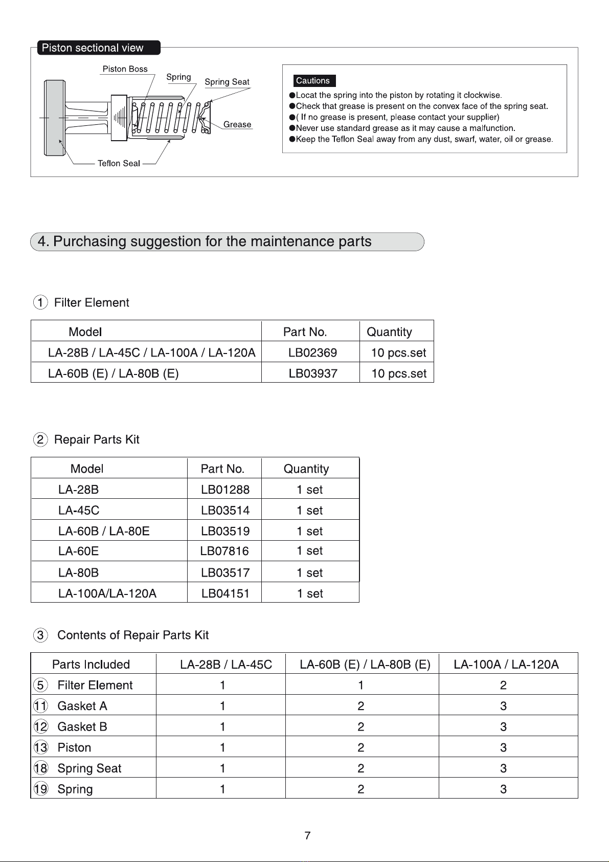
Piston cross-sectional view
Sliding part (black)
Grease
Spring Seat
Spring
Piston Boss CAUTION
●Fix the spring into the piston by rotating
it clockwise.
●Check that grease is present on the
convex face of the spring seat.
(If no grease is present, please contact
your supplier)
●Never use standard grease as it may
cause a malfunction.
●Keep the Sliding part away from dust,
swarf, water, oil or grease.
1. Precautions
(1) Our blower is an oil-free type; therefore, never lubricate the blower.
(2) The main unit of the blower is precisely adjusted; therefore, never disassemble the unit.
(Never loosen the eight hexagonal-head bolts on the rear of the main unit.)
&OHDQLQJDQGUHSODFHPHQWRI¿OWHUHOHPHQW
(1) Be sure to perform cleaning or replacement after disconnecting the power plug from the electric
outlet.
(2) Loosen the
①Bind screw, and remove the ③Filter cover.
(3) Take out the ④Filter element from the ⑤Upper Case, replace the element with new one or
FOHDQWKHHOHPHQW$WWKLVPRPHQWZLSHGXVWRIIWKH¿OWHUHOHPHQWPRXQWLQJIDFHDQGVXFWLRQ
port of the ⑤Upper Case with a cloth or the like.
(4) Clean the
④Filter element as follows
(a) Beat the ④)LOWHUHOHPHQWWRGURSGXVWVXI¿FLHQWO\
(b) If the element is severely dirty, use a neutral detergent to wash it, rinse it well, and dry it in the
shade.
&RQ¿UPWKDWWKH②Filter Cover Gasket is attached to the ③Filter cover.
(6) Be sure to mount the ③Filter cover, and secure it with the ①Bind screw.
:KHQUHSODFLQJWKH¿OWHUHOHPHQWEHVXUHWRXVHDJHQXLQH¿OWHUHOHPHQW)DLOXUHWRREVHUYH
this may cause a malfunction.
+RZWRUHSODFHWKHSLVWRQ
(1) Be sure to perform replacement after disconnecting the power plug from the electric outlet.
(2) Remove the
⑤Upper Case, loosen the ⑧Hexagonal-head bolts using a box wrench, and
remove the ⑨Head Cover. If the gasket is glued too tightly to remove the cylinder cover, insert
DÀDWEODGHVFUHZGULYHULQWRWKHJURRYHIRUÀDWEODGHVFUHZGULYHURIWKH⑨Head Cover and
gently separate them.
(3) Pull out the ⑮3LVWRQVHW¿OWHUHOHPHQWDVIROORZV
(4) Replace the
⑮Piston set, ⑩Gasket A, and ⑪Gasket B with new ones. Be absolutely careful
not to let dirt, oil, or other foreign matter attach to the sliding part (black part) of the ⑫Piston
assembly. Do not touch the moving parts as much as possible. (For the ⑮Piston set re-
placement, be sure to replace two sets of the assemblies at the same time.)
(5) Insert the
⑮Piston set into the ⑯Blower main unit, mount the ⑩Gasket A on the ⑨Head
Cover, mount the ⑪Gasket B on the ⑯Blower main unit without displacement, and tighten
the ⑨Head Cover with the ⑧Hexagonal-head bolts. When tightening the ⑧Hexagonal-head
EROWVWLJKWHQWKHPXQLIRUPO\ELWE\ELWDQGWLJKWHQWKHP¿UPO\DWWKHHQG
(6) For LA-60A and 80A, lightly press the ⑨Head Cover of the ⑯Blower main unit.
(This operation is performed to ensure the ⑰Nozzle seal and discharge port peripheral seal.)
$IWHUDVVHPEO\FRQQHFWWKHSRZHUSOXJWRWKHHOHFWULFRXWOHWDQGRSHUDWHWKHSURGXFW&RQ¿UP
that there is no air leakage from the ⑨Head Cover, ⑰Nozzle seal, and other areas while
EORFNLQJWKHGLVFKDUJHQLSSOHZLWK\RXU¿QJHU,IDLUOHDNDJHLVIRXQGWLJKWHQWKH⑧Hexagonal-
head bolts uniformly again, or check to see whether the ⑩Gasket A and ⑪Gasket B are
appro-priately placed.
(8) If there is no problem, put the ⑤Upper Case on the ⑯Blower main unit and tighten six pieces
of the ⑥%LQGVFUHZVXQLIRUPO\ELWE\ELWDIWHUFRQ¿UPLQJWKDWWKH⑦Gasket C is securely placed.
([SORGHG9LHZ/$$/$$
⑯Blower
Main Unit
Never loosen these eight(8) Hex.
Bolts on the Endcap.
Air Outlet
Bottom Case
Slot for screwdriver
Outlet Port
⑰Nozzle Seal
⑫Piston ASSY
⑬Spring
⑭Spring Seat ⑮Piston Set
⑩Gasket A
⑪Gasket B
⑦Gasket C
⑧Hexagonal-Head Bolts
⑨Head Cover
②Filter Cover Gasket
④Filter Element
⑤Upper Case
①Bind Screw
⑥Bind Screws
③Filter Cover
([SORGHG9LHZ/$%/$(/$%/$(
①Bind Screw
③Filter Cover
④Filter Element
⑥Bind Screws
⑦Gasket C
⑧Hexagonal-Head Bolts
⑩Gasket A
⑪Gasket B ⑫Piston ASSY
⑬Spring
⑭Spring Seat ⑮Piston Set
⑯Blower
Main Unit
Never loosen these eight(8) Hex.
Bolts on the Endcap.
Air Outlet
Slot for screwdriver
Bottom Case
⑨Head Cover
②Filter Cover Gasket
⑤Upper Case
Outlet Port
Other manuals for LA-28B
1
This manual suits for next models
7
Table of contents
Other MEDO Blower manuals


