Kenmore 2335994690 Operating instructions

Downdraft Blower
Use & Care /Installation Manual
Ventilador de tiro descendente
Manual de uso y cuidado /instalaci6n
Models
Modelos 233.5994090
233.5994690
rtl
Z
C)
!--
-I-
rrl
t.n
"O
Z_
O
r-"
99042589K Sears, Roebuck and Co., Hoffman Estates, IL 60179 U.S.A. www.sears.com

SECTION ..................................................................... PAGE
Warranty .............................................................................. 2
Safety Instructions ............................................................... 2
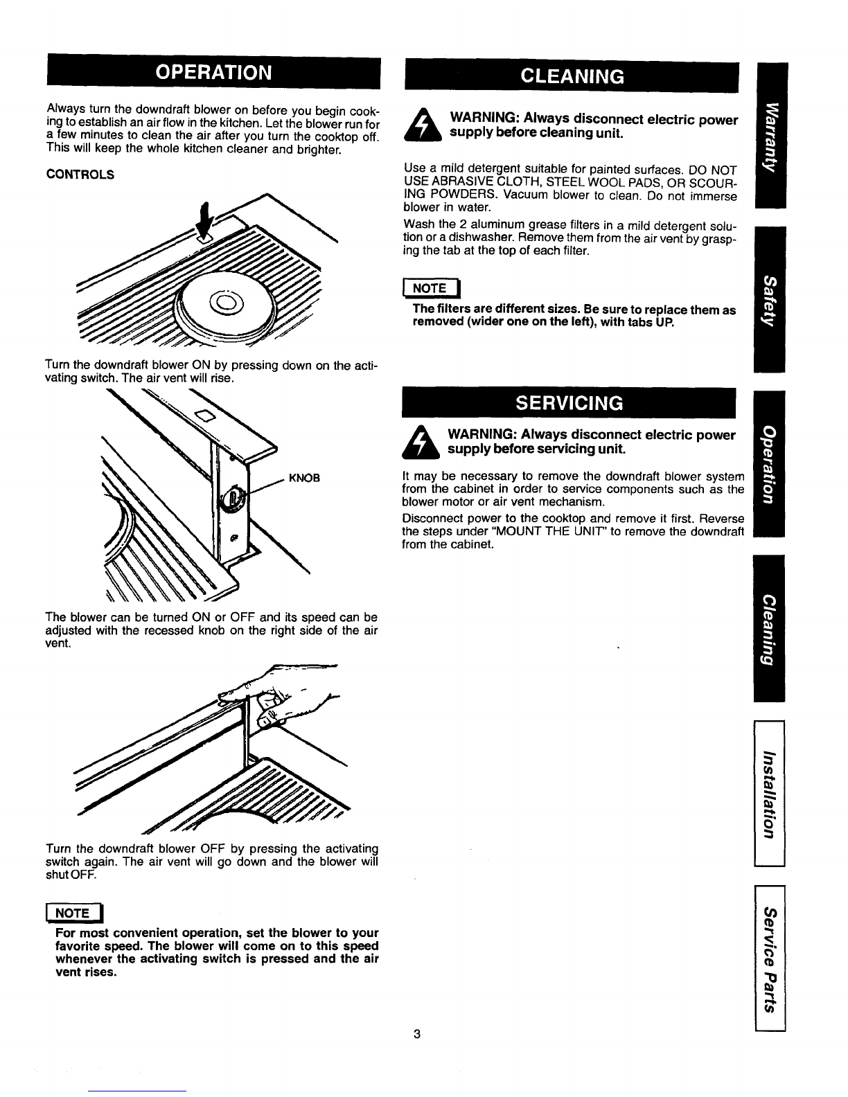
Operation ............................................................................. 3
Cleaning, Servicing ............................................................ 3
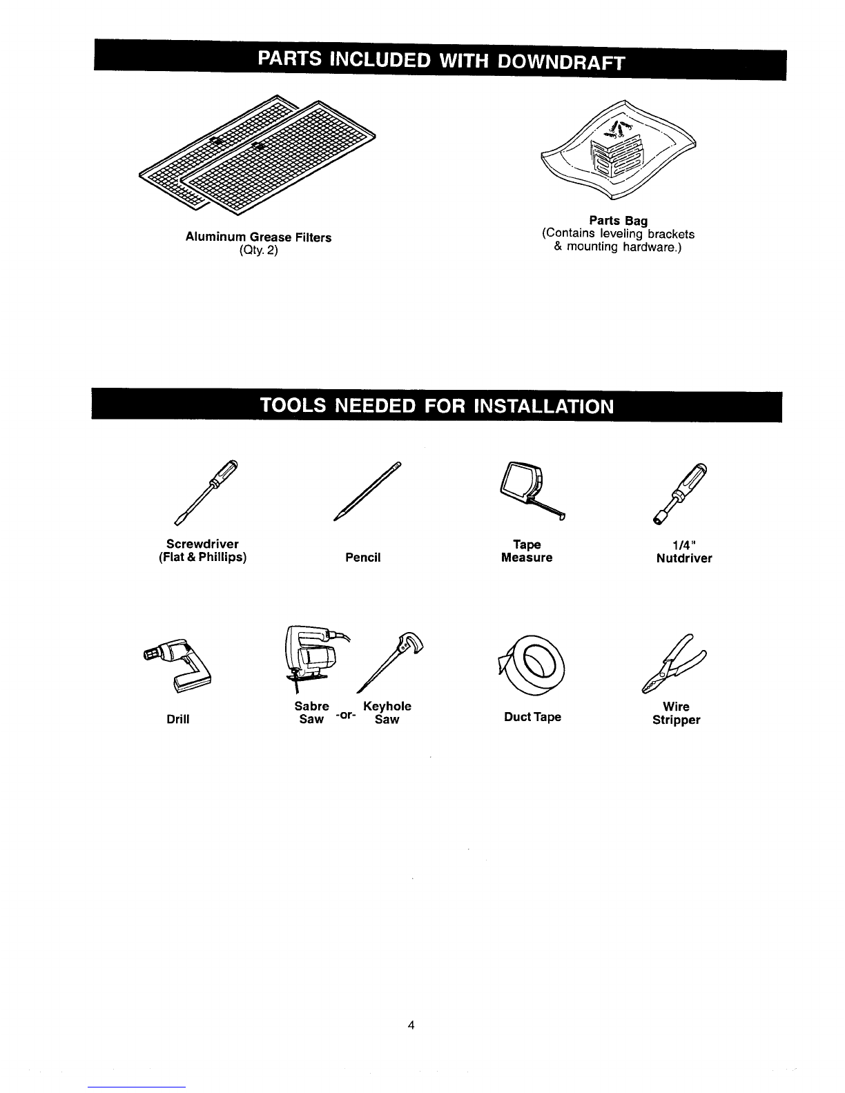
Parts Included With Downdraff ........................................... 4
Tools Needed For Installation ............................................ 4
Equivalent Duct Length Chart ............................................ 5
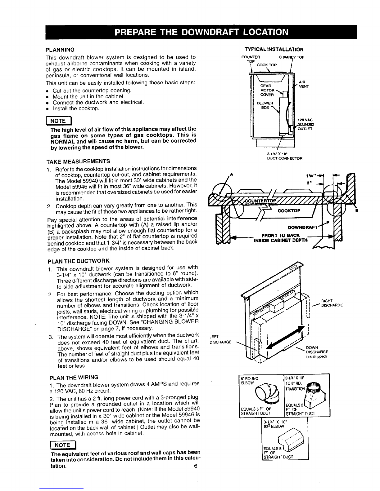
Prepare The Downdraft Location ......................... _.............. 6
Prepare The Downdraft ...................................................... 7
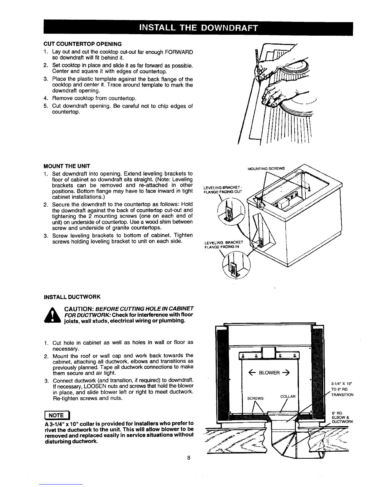
Install The Downdraft .......................................................... 8
Connect The Wiring ............................................................ 9
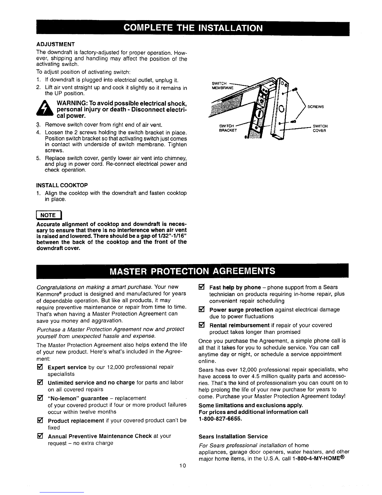
Complete The Installation ................................................. 10
Master Protection Agreements ........................................ 10
Service Parts ..................................................................... 11
If within 1 year from the date of installation, any part of this
downdraft fails to function properly due to a defect in material
or workmanship, Sears will repair the part or furnish and
install a new part, free of charge.
FULL 30-DAY WARRANTY ON FINISH ON PAINTED OR
BRIGHT METAL PARTS
Ifwithin 30 days from the date ofinstallation,the finishon any
)ainted or brightmetal parts of this downdraft is defective in
material or workmanship, Sears will furnish and install a new
part, free of charge.
WARRANTY SERVICE IS AVAILABLE BY CONTACTING
THE NEAREST SEARS SEVICE CENTER/DEPARTMENT
IN THE UNITED STATES.
This warranty applies only while this product is in use in the
United States. This warranty gives you specific legal rights
and you may have other rights which vary from state to state.
Sears, Roebuck and Co., Dept 81";WA, Hoffman Estates,
IL 60179
INTENDED FOR DOMESTIC COOKING ONLY A
WARNING Z'_
TO REDUCE THE RISK OF FIRE, ELECTRIC SHOCK, OR
INJURY TO PERSONS, OBSERVE THE FOLLOWING:
1. Use this unit only in the manner intended by the
manufacturer. If you have questions, contact the
manufacturer at the address listed in the warranty.
2. Before servicing or cleaning unit, switch power off at
service panel and lock the service disconnecting means
to prevent power from being switched on accidentally.
When the service disconnecting means cannot be locked,
securely fasten a prominent warning device, such as a
tag, to the service panel.
3. Installation work and electrical wiring must be done by a
qualified person(s) in accordance with all applicable codes
and standards, including fire-rated codes and standards.
4. Sufficient air is needed for proper combustion and
exhausting of gases through the flue (chimney) of fuel
burning equipment to prevent backdrafting. Follow the
heating equipment manufacturer's guideline and safety
standards such as those published by the National Fire
Protection Association (NFPA), and the American Society
for Heating, Refrigeration and Air Conditioning Engineers
(ASHRAE), and the local code authorities.
5. When cutting or drilling into wall or ceiling, do not damage
electrical wiring and other hidden utilities.
6. Do not use this unit with an additional speed control device.
7. Ducted fans must always be vented to the outdoors.
8. To reduce the risk of fire, use only metal ductwork.
9. Do not install this product with the activating switch directly
behind a burner or element. Minimum distance between
the switch and the edge of the burner should be 4 inches.
10. Loose-fitting or hanging clothing should never be worn
when operating this appliance. They may be ignited by
burners/elements on cooktop.
11.Children should not be left alone or unattended in the
area where this appliance is in use.
12. This unit must be grounded.
2
WARNING Z'i z_
TO REDUCE THE RISK OF A RANGE TOP GREASE FIRE:
1. Never leave surface units unattended at high settings.
Boilovers cause smoking and greasy spillovers that may
ignite. Heat oils slowly on low or medium settings.
2. Always turn hood ON when cooking at high heat or when
cooking flaming foods.
3. Clean ventilating fans frequently. Grease should not be
allowed to accumulate on fan or filter.
4. Use proper pan size. Always use cookware appropriate
for the size of the surface element.
TO REDUCE THE RISK OF INJURY TO PERSONS IN THE
EVENT OF A RANGE TOP GREASE FIRE, OBSERVE THE
FOLLOWING:*
1. SMOTHER FLAMES wit6 a close-fitting lid, cookie sheet,
or metal tray, then turn off the burner. BE CAREFUL TO
PREVENT BURNS. If the flames do not go out immediately,
EVACUATE AND CALL THE FIRE DEPARTMENT.
2. NEVER PICK UP A FLAMING PAN -You may be burned.
3. DO NOT USE WATER, including wet dishcloths or towels
- a violent steam explosion will result.
4. Use an extinguisher ONLY if:
A. You know you have a Class ABC extinguisher and you
already know how to operate it.
B. The fire is small and contained in the area where it
started.
C. The fire department is being called.
D. You can fight the fire with your back to an exit.
* Based on "Kitchen Firesafety Tips" published by NFPA.
CAUTION
1. For general ventilating use only. Do not use to exhaust
hazardous or explosive materials and vapors.
2. To avoid motor bearing damage and noisy and/or
unbalanced impellers, keep drywall spray, construction
dust, etc. off power unit.
3. Clean filters and grease-laden surfaces frequently.
4. Do not repair or replace any part of this appliance unless
specifically recommended in this manual. All other servicing
should be done by a qualified technician.
5. Please read specification label on product for further
information and requirements.

Alwaysturnthedowndraftbloweronbeforeyoubegincook-
ingtoestablishanairflowinthekitchen.Lettheblowerrunfor
afewminutestocleantheairafteryouturnthecooktopoff.
Thiswillkeepthewholekitchencleanerandbrighter.
CONTROLS
_ARNING: Always disconnect electric power
supply before cleaning unit.
Use amild detergent suitable for painted surfaces. DO NOT
USE ABRASIVE CLOTH, STEEL WOOL PADS, OR SCOUR-
ING POWDERS. Vacuum blower to clean. Do not immerse
blower in water.
Wash the 2 aluminum grease filters in a mild detergent solu-
tion or a dishwasher. Remove them from the air vent by grasp-
ing the tab at the top of each filter.
I NOTE J
The filters are different sizes. Be sure to replace them as
removed (wider one on the left), with tabs UP.
Turn the downdraft blower ON by pressing down on the acti-
vating switch. The air vent will rise.
KNOB
WARNING: Always disconnect electric power
supply before servicing unit.
It may be necessary to remove the downdraft blower system
from the cabinet in order to service components such as the
blower motor or air vent mechanism.
Disconnect power to the cooktop and remove it first. Reverse
the steps under "MOUNT THE UNIT" to remove the downdraft
from the cabinet.
The blower can be turned ON or OFF and its speed can be
adjusted with the recessed knob on the right side of the air
vent.
Turn the downdraft blower OFF by pressing the activating
switch again. The air vent will go down and the blower will
shut OFF.
5"
I
I NOTE I
For most convenient operation, set the blower to your
favorite speed. The blower will come on to this speed
whenever the activating switch is pressed and the air
vent rises.
rB ;
=-. i
"-t
3

Aluminum Grease Filters
(Qty.2)
Parts Bag
(Contains leveling brackets
& mounting hardware.)
/
Screwdriver
(Flat & Phillips)
/
Pencil
qL
Tape
Measure
/114"
Nutdriver
,%
Drill Sabre Keyhole
Saw -or- Saw Duct Tape Wire
Stripper

Kenmore range hoods are designed to perform efficiently when attached to long runs of duct. As a point of reference, this hood
will function at approximately 80% of its rated air flow when 200 equivalent feet of 7" round ductwork is attached. Use this chart
to calculate the equivalent duct length of your system.
Broan Model 401
Straight Duct
3V4-in. x 10-in. x 2-ft. long
Equivalent length
2ft. 0
Broan Model 406
Straight Duct
6-in. round x 2-ft. long
Equivalent length
2ft. O
Broan Model 407
Straight Duct
7-in. round x 2-ft. long
Equivalent length
2ft.
Broan Model 419
6-in. Round Elbow
Equivalent length
8ft.
Broan Model 415
7-in. Round Elbow
Equivalent length
8ft.
Sears Model 59581
31/4-in.x 10-in. to
6-in. Round Transition
Equivalent length
5.5 ft.
Broan Model 412H
31/,-in. x 10-in. to
7-in. Round
Transition
Equivalent length
5.5 ft.
Broan Model 428
3Y4-in. x 10-in.
Right-angle Elbow
Equivalent length
8.5 ft.
Broan Model 429
31/4-in.x 10-in.
Right-angle Flat Elbow
Equivalent length
24ft.
Broan Model 430
31,_-in.x 10-in.
Right-angle
Short
Eave Elbow
Equivalent length
15ft.
Broan Model 431
31/4-in.x 10-in.
Right-angle
Long
Eave Elbow
Equivalent length
15ft.
_ Sears Model 59691
6-in. Round
Wall Cap
Equivalent length
34 ft.
(6-ft. w/o damper)
(_ Broan Model 647
7-in. Round
Wall Cap
Equivalent length
34 ft.
(6-ft. w/o damper)
Sears Model
59391
31/4-in.x
10-in.
Wall Cap
Equivalent
length
45 ft.
(7-ft. w/o damper)
Sears
Model 59091
Roof Cap
(accepts 7-in. round
or 31/4-in.x 10-in. duct)
Equivalent length
30 ft. (7-ft. w/e damper)
Sears Model "Ducting Accessories" available by calling Sears at
1-800-4-MY-HOME ®
Broan Model "Ducting Accessories" available by calling:
1-800-558-1711.
i
i.
!
tb

PLANNING
This downdraft blower system is designed to be used to
exhaust airborne contaminants when cooking with avariety
of gas or electric cooktops. It can be mounted in island,
peninsula, or conventional wall locations.
This unit can be easily installed following these basic steps:
• Cut out the countertop opening.
• Mount the unit in the cabinet.
• Connect the ductwork and electrical.
• Install the cooktop.
INOTE
The high level of air flow of this appliance may affect the
gas flame on some types of gas cooktops. This is
NORMAL and will cause no harm, but can be corrected
by lowering the speed of the blower.
TAKE MEASUREMENTS
1. Refer to the cooktop installation instructions for dimensions
of cooktop, countertop cut-out, and cabinet requirements.
The Model 59940 will fit in most 30" wide cabinets and the
Model 59946 willfit in most 36" wide cabinets. However, it
is recommended that oversized cabinets be used for easier
installation.
2. Cooktop depth can vary greatly from one to another. This
may cause the fit of these two appliances to be rather tight.
Pay special attention to the areas of potential interference
highlighted above. A countertop with (A) a raised lip and/or
(B) a backsplash may not allow enough flat countertop for a
proper installation. Note that 2" of flat countertop is required
behind cooktop and that 1-3/4" is necessary between the back
edge of the cool<top and the inside of cabinet back.
TYPICAL INSTALLATION
COUNTER CHIM N_Y "lOP
TOP _'
1 "°" I
GEAR
MOTOR "_ f'-I
COVER .._
BLOWER
BOX
f,
i
AiR
/VENT
f20 VAC
3,1t4" X 10"
DUCT CONNECTOR
FRONT TO BACK
INSIDE CABINET DEPTH
PLAN THE DUCTWORK
1. This downdraft blower system is designed for use with
3-1/4" x 10" ductwork (can be transitioned to 6" round)•
Three different discharge directions are available with side-
to-side adjustment for accurate alignment of ductwork.
2. For best performance: Choose the ducting option which
allows the shortest length of ductwork and a minimum
number of elbows and transitions. Check location of floor
joists, wall studs, electrical wiring or plumbing for possible
interference. NOTE: The unit is shipped with the 3-1/4" x
10" discharge facing DOWN. See "CHANGING BLOWER
DISCHARGE" on page 7, if necessary.
3. The system will operate most efficiently when the ductwork
does not exceed 40 feet of equivalent duct• The chart,
above, shows equivalent feet of elbows and transitions.
The number of feet of straight duct plus the equivalent feet
of transitions and/or elbows to be used should equal 40
feet or less.
LEFT
DISCHARGE
• °.o..
/J!i1-o,sc.A.
i.!
,4.=-
PLAN THE WIRING
1. The downdraft blower system draws 4 AMPS and requires
a 120 VAC, 60 Hz circuit.
2. The unit has a 2 ft. long power cord with a3-pronged plug•
Plan to provide a grounded outlet in a location which will
allow the unit's power cord to reach. (Note: If the Model 59940
is being installed in a 30" wide cabinet or the Model 59946 is
being installed in a 36" wide cabinet, the outlet cannot be
located on the back wall of cabinet.) Outlet may also be wall-
mounted, with access hole in cabinet.
I NOTE I
The equivalent feet of various roof and wall caps has been
taken into consideration. Do not include them in this calcu-
lation, 6
6" ROLIN0 13-1/4" X10"
TRANSITI
[eQUALS2L._/
FQUALS 6 FT OF IFT. OF
STRAIGHT OUCT ISTRAIGHT DUCT
3-'_/4"X 10'
900ELBOW
QUALS_
OF
PbMGFITDUCT

CHANGING BLOWER DISCHARGE (Optional)
The blower is shipped with its discharge facing DOWN. Fol-
low these steps ONLY if:
•the positionof the blower discharge needs tobe moved
so ductwork does not interfere with floor.joists, plumb-
ing or wiring below.
•it is necessary to rotate the blower discharge to the
RIGHT or LEFT.
Place the uniton its back on a table or work surface.
DOWN DISCHARGE - MOVING BLOWER LEFT OR RIGHT
1. Loosen the 4 nuts and 2 clamp channels.
2. Slide blower to desired position.
3. Use supplied cover plate to close open space (if any).
4. Tighten nuts to secure top of blower and use sheet metal
screws through bottom flange to secure bottom of blower.
LEFT OR RIGHT DISCHARGE
1. Remove the 4 nuts and 2 clamp channels.
2. Carefully lift blower and disconnect motor plug if necessary.
Reposition blower and RECONNECT MOTOR PLUG.
3. Use supplied cover plate to close open space (if any).
4. Replace clamp channels and use nuts to secure the blower
in its new position.
5. Use sheet metal screws through bottom flange to secure
bottom of blower.
SHEET
NUT
BOTTOM
FLANGE
S8LOWE R
_.__ ,,,/,_ _.
= _ /Y/ MOTOR
jVVl I-- SHEE_
- _ T -"METAL
L-- ",,,, /
_COVER PLATE
2
0
m
J
.
r_l
I
I
J
7

CUT COUNTERTOP OPENING
1. Lay outand cut the cooktop cut-out far enough FORWARD
so downdraft will fit behind it.
2. Set cooktop in place and slide itas far forward as possible.
Center and square it with edges of countertop.
3. Place the plastic template against the back flange of the
cooktop and center it. Trace around template to mark the
downdraft opening.
4. Remove cooktop from countertop.
5. Cut downdraff opening. Be careful not to chip edges of
countertop.
MOUNT THE UNIT
1. Set downdraft into opening. Extend leveling brackets to
floor of cabinet so downdraff sits straight. (Note: Leveling
brackets can be removed and re-attached in other
positions. Bottom flange may have to face inward in tight
cabinet installations.)
2. Secure the downdraft to the countertop as follows: Hold
the downdraft against the back of countertop cut-out and
tightening the 2 mounting screws (one on each end of
unit) on underside of countertop.Use awood shim between
screw and underside of granite countertops.
3. Screw leveling brackets to bottom of cabinet. Tighten
screws holding leveling bracket to unit on each side.
fvIOLINTING SCREWS
FLANGI_ FACING OUT
LEVF_.LINQ BRACKET I._"'"
FLANGE FACING IN
INSTALL DUCTWORK
_liL CAUTION: BEFORE CUTTING HOLE IN CABINET
FOR DUCTWORK: Check for interference with floor
joists, wall studs, electrical wiring or plumbing.
1. Cut hole in cabinet as well as holes in wall or floor as
necessary.
2. Mount the roof or wall cap and work back towards the
cabinet, attaching all ductwork, elbows and transitions as
previously planned. Tape all ductwork connections to make
them secure and air tight.
3. Connect ductwork (and transition, if required) to downdraft.
If necessary, LOOSEN nuts and screws that hold the blower
in place, and slide blower left or right to meet ductwork.
Re-tighten screws and nuts.
INOTE I
A 3-1/4" x 10" collar is provided for installers who prefer to
rivet the ductwork to the unit. This will allow blower to be
removed and replaced easily in service situations without
disturbing ductwork.
i
C
(--BLOWER--->
SCREWS COLLAR
J S-
3-1/4" X 10"
TO 6" RD.
6" RD,
ELBOW &
DUCTWORK
_.._.-'.;"
-.-_.

INSTALL ELECTRICAL WIRING
1. Mount a standard wiring box, with 3-pronged receptacle,
inside the cabinet. Make sure the downdraft's power cord
can easily reach it.
2. Run appropriate power cable into cabinet and connect it
to receptacle.
3. Plug the downdraft's power cord into the outlet.
WIRING DIAGRAM
_._ vAc
/ ! _ _ .LK J
[_,,,= _- o-
/I _lt I_ _,, IN.U
_J
J
_t
,,,,,dl I
CD I
"DI
9

ADJUSTMENT
The downdraft is factory-adjusted for proper operation. How-
ever, shipping and handling may affect the position of the
activating switch.
To adjust position of activating switch:
I. If downdraft is plugged into electrical outlet, unplug it.
2. Lift air vent straight up and cock it slightly so it remains in
the UP position.
_WARNING: To avoid possible electrical shock,
personal injury or death - Disconnect electri-
cal power.
3. Remove switch cover from right end of air vent.
4. Loosen the 2 screws holding the switch bracket in place.
Position switch bracket so that activating switch just comes
in contact with underside of switch membrane. Tighten
screws.
5. Replace switch cover, gently lower air vent into chimney,
and plug in power cord. Re-connect electrical power and
check operation.
INSTALL COOKTOP
1. Align the cooktop with the downdraft and fasten cooktop
in place.
INOTE I
Accurate alignment of cooktop and downdraft is neces-
sary to ensure that there is no interference when air vent
is raised and lowered. There should be a gap of 1/32"-1/16"
between the back of the cooktop and the front of the
downdraft cover.
SWITCH
MEMBRANE
SCREWS
SWITCH
COVER
Congratulations on making a smart purchase. Your new
Kenmore ®product is designed and manufactured for years
of dependable operation. But like all products, it may
require preventive maintenance or repair from time to time.
That's when having a Master Protection Agreement can
save you money and aggravation.
Purchase a Master Protection Agreement now and protect
yourself from unexpected hassle and expense.
The Master Protection Agreement also helps extend the life
of your new product. Here's what's included in the Agree-
ment:
[] Expert service by our 12,000 professional repair
specialists
[] Unlimited service and no charge for parts and labor
on all covered repairs
[] "No-lemon" guarantee - replacement
of your covered product if four or more product failures
occur within twelve months
[] Product replacement if your covered product can't be
fixed
[] Annual Preventive Maintenance Check at your
request - no extra charge
10
[] Fast: help by phone - phone support from a Sears
technician on products requiring in-home repair, plus
convenient repair scheduling
[] Power surge protection against electrical damage
due to power fluctuations
[] Rental reimbursement if repair of your covered
product takes longer than promised
Once you purchase the Agreement, a simple phone call is
all that it takes for you to schedule service. You can call
anytime day or night, or schedule a service appointment
online.
Sears has over 12,000 professional repair specialists, who
have acc'ess to over 4.5 million quality parts and accesso-
ries. That's the kind of professionalism you can count on to
help prolong the life of your new purchase for years to
come. P_rchase your Master Protection Agreement today!
Some limitations and exclusions apply.
For prices and additional information call
1-800-8;).7-6655.
Sears Installation Service
For Sears professiona/ insta//ation of home
appliances, garage door openers, water heaters, and other
major home items, in the U.S.A. call 1-800-4-MY-HOME®

KEY
NO.
1
2
3
4
5
6
7
8
9
10
11
12
16
17
18
19
2O
21
22
23
24
26
27
28
29
30
31
32
33
45
45
47
49
5O
51
52
53
54
55
23 71
/12
54
PART
NO.
93400038
994OO061
99400024
93470012
97011238
97010714
9926O491
99360165
99100492
97009972
97011 293
97010993
98007642
98007780
98008168
97011325
97011326
99080362
99020247
98008167
9971 OO32
97O13944
97011445
97011446
97013941
97013942
97013943
97017025
97011443
97010994
97010992
98008150
98008157
97009786
97009787
99090905
99080590
99110850
99170245
99150471
99150491
99150488
98008158
98008185
99260488
98008144
98008169
DESCRIPTION QTY.
Bushing, 7/8"
Bushing, Split Heyco, 5/8"
Bushing, Heyco, 1/2"
Roller
Switch Assembly, Up/Down
Wire Harness, Speed Control
Nut, 3/8-32
Knob
Motor Isolator
Lower Switch Bracket Assembly
Green Ground Wire
Wire Harness
Back-up Plate
Crank
Switch Cover
Chimney Assembly with Slide (Model 59940)
Chimney Assembly with Slide (Model 59946)
Motor (with Capacitor-Key No. 73)
Blower Wheel
Scroll Box Extension
Spacer
Top Bracket Assembly, RH & LH
30" Top, Stainless (Model 59940)
36" Top, Stainless (Model 59946)
End Cap, Black (2 provided)
End Cap, White (2 provided)
End Cap, Almond (2 provided)
Scroll Box Assembly
Gear Motor Cover Assembly
Air Box Assembly (Model 59940)
Air Box Assembly (Model 59946)
Scroll Box Cover
Capacitor Strap
Filter Kit (Model 59940) (contains 2 filters)
Filter Kit (Model 59946) (contains 2 filters)
End Cap
Gearmotor
Slide Strip
Screw, #8-18 x .375 SLT HX WS HD
Screw, #10-32 x .500 HX WS BDRH
Screw, #8-18 x .375SR
Screw, #8-18 x 500 No. 5 PH Tnm
Cover, Air Box Opening (Model 59940)
Cover, Air Box Opening (Model 59946)
Nut, Whiz 0-24
Air Box Cover (Model 59940
Air Box Cover (Model 59946)
1
1
1
1
1
1
1
1
3
1
1
1
1
1
1
1
1
1
1
1
2
1
1
1
2
1
1
1
1
1
1
1
1
1
1
3
19
2
6
2
1
1
4
1
1
25
3
26
19
"71
45
71
84
22 31
KEY PART
NO. NO.
56 97011500
57 98008159
58 99150536
60 99150479
61 99160356
62 99160361
64 99260437
65 99260477
66 99380633
67 99400048
68 93260447
70 98008415
71 93270493
73 99271000
74 99160384
75 99150415
83 99420551
84 99100503
99100504
"97011311
97011320
970i 1321
DESCRIPTION QTY.
Gearmotor Bracket Assembly 1
Leg Support 2
Screw, 1/4-20 x 5/16 5
Screw, #8-32 x 1/2 PH HD MS 4
Screw, #10-24 x 3/8 SH WH LOCK 1
Screw, #10-24 x 3/8 PH FL HD LD 1
Nut, 10-24 HEX KEPS 7
Nut, 1/4-20 WHIZ LOCK 3
U-Bolt, 10-24 1
Strain Relief 1
Nut, Hex Flange 1
Wire Channel Clamp 2
Wire Tie 3
Capacitor 1
Screw, 1/4-20 x 2.000 Hex. Hd. 2
#8-18 x .250 PH TR HD BPT
Plastic Clip 1
Foam Seal (59940) 1
Foam Seal (59946) 1
Blower Assembly, Complete (Includes Key
Nos. 2, 9, 20, 21, 22, 28, 31, 32, 49, 58,
64, 65, & 73)
Chimney Assembly, Complete (Model
59940) (Includes Key Nos. 5, 8, 19, 45, 51,
52, & 71)
Chimney Assembly, Complete (Model
59946 (includes Key Nos. 5, 8, 19, 45, 51,
52, &71)
* Standard Hardware May be purchased locally
*_ Service Assembl,' -Contains numerous parts
MODEL NO. DESCRIPTION
59941 Optional Door Kit, 30" White
59942 Optional Door Kit, 30" Black
59944 Optional Door Kit, 30" Biscuit
59947 Optional Door Kit, 36" White
59948 Optional Door Kit, 36" Black
59945 Optional Door Kit, 36" Biscuit
.___J
Cnl
m
2
O
m
m
m
m
5"
O
::3
11

SECCION ................................................................. PAGINA
Garantia ............................................................................. 12
Instrucciones de seguridad .............................................. 12
Operaci6n .......................................................................... 13
Limpieza y servicio ........................................................... 13
Plazas incluidas con del ventilador de tiro
descendente ._..._............................................................... 14
Herramientas necesarias para la instalaci6n ................... 14
Cuadro de longitudes equivalentes de ducto ................... 15
Prepare la ubicaci6n del ventilador de tiro
descendente ..................................................................... 16
Prepare el ventilador de tiro descendente ....................... 17
Instale el ventilador de tiro descendente .......................... 18
Haga las conexiones electricas ........................................ 19
T_rmine '.a instalaci6n ........................................................ 20
Acuerdos de Protecci6n Maestros .................................... 20
Piezas de servicio ........................................................... 21
Si dentro de 1 a_o de la fecha de la instalaci6n, cualquier parte de este
ventilador de tiro descendente deja de funcionar en forma apropiada
debido a defeoto en el material o mano de obra, Sears reparard la pieza
afectade o pn:_veer8 einstalara una pieza nueva sin cargo.
GARANTiA COMPLETA DE 30 DIAS EN EL ACABADO DE PIEZAS
PINTADAS O DE METAL LUSTROSO
Si dentro de los 30 dfas de la fecha de instalacion, el acabado de
cualquier pieza pintada o de metal lustroso de esta campana de
cocina presenta defecto de material omano de obra, Sears proveera
e instal__ra una pieza nueva sin cargo.
EL SERVICI,O DE GARANT[A SE OBTIENE PONIENDOSE EN
CONTACTO CON EL CENTRO DE SERVICIO O DEPARTAMENTO
SEARS MAS CERCANO EN LOS ESTADOS UNIDOS.
Esta garantfa es vdifda 0nicamente sieste producto se encuentra en
uso dentro de los Estados Unidos. Esta garantia le confiere derechos
legales especificos y Ud. puede tener adema.s otros derechos qua
varian de estado a estado.
Sears, Roebuck and Co., Dept 817WA, Hoffman Estates, IL 60179
PREVISTO PARA COClNAR DI_MSTICO SOLAMENTE.
ADVERTENCIA Z'_ _._ ADVERTENCIA Z'_
PARA REDUCIR EL RIESGO DE INCENDIO, CHOQUE ELI_CTRICO
O LESIONES A PERSONAS, CUMPLA CON LAS SIGUIENTES
INDICACIONES:
1. Utilice esta unidad solo en la manera prescrita pot el fabricante.
Para cualquier pregunta, pbngase en contacto con el fabdcante en
la direccibn o al t@lefono indicados en la garantia.
2. Antes de efectuar alg0n servicio o limpieza, desconecte la corriente
electrica en el tablero de servicio y cierre con Ilave el medio de
desconexi6n del servicio para evitar que la corriente sea conectada
accidentalmente. Cuando el medio de desconexi6n del servicio no
pueda cerrarse con Ilave, ponga en el tablero de servicio un dispositivo
de advertencia muy visible, como por ejemplo, una etiqueta.
3. Todo trabajo de instalacion y cableado el@ctrico debeser realizado
por personal calificado y de acuerdo con todos los c6digos y normas
pertinentes, incluyendo los c6digos y normas relacionados con la
construccibn clasificada para inoendio.
4. Se necesita de la cantidad suficiente de aire :para la adecuada
combusti6n y evacuaci6n de gases por la chimenea de la unidad y
para evitar que se formen corrientes gaseosas de tiro invertido. Siga
las instrucciones y medidas de seguddad del fabdcante del equipo,
tales como las publicadas por la National Fire Protection Association
(NFPA) y la American Society for Heating, Refrigeration and Air
Conditioning Engineers (ASHRAE) y las autoridades locales de
codigos de seguridad.
5. AI cortar o perforar la pared o el techo, tenga cuidado para no daSar
el cableado electrico u otros servicios peblicos ocultos.
6. No utilice en esta unidad otros dispositivos de control de velocidad
adicionales.
7. Los ventiladores canalizados deber_.n siempre descargarse hacia
el exterior.
8. Para reducir el riesgo de incendio, use solo ductos de metal.
9. Cuando instale este producto, tenga cuidado de que que el
interruptor de activacibn no quede directamente encima de ning0n
elemento u hornilla. La distancia minima qua debe existir entre el
interruptor y la orilla de una homilla debe ser de al menos 10 cm
(4 pulg.).
10. Nunca use accesorios sueltos ni ropa holgada cuando haga uso de
este aparato. Las hornillas/elementos de la superficie de la estufa
pueden hacer que se incendien.
11. Cuando este utilizando este aparato nunca deje a los ni_os solos o
sin vigilar en el _.rea donde este se encuentra.
12, Esta unidad se debe instalar con conexidn a tierra.
12
PARA REDUCIR EL RIESGO DE UN INCENDIO POR GRASA EN LA
ESTUFA:
1. Nunca deje las unidades de superficie sin supervisi6n cuando tengan
ajustes altos. Los reboses pueden provocar humo y derrames
grasosos que se pueden incendiar. Caliente lentamente el aceite
en un ajuslEe bajo o medio.
2. Siempre ENCtENDA la campana cuando cocine con alta temperatura
o cuando (;ocine alimentos que se puedan incendiar.
3. Limpie con frecuencia los ventiladores. No debe permitir que la
grasa se aoumule en el ventilador ni en el filtro.
4. Utilice un .,;aden de tamaSo adecuado. Siempre utilice el utensilio
adecuado al tamano del elemento de superficie.
PARA REDUCIR EL RIESGO DE LESIONES A PERSONAS EN
CASO DE INCFNDIO DE LA GRASA DE LA ESTUFA, OBEDEZCA
LAS SIGUIENTE INDICACIONES*:
1. SOFOQUE LAS LLAMAS usando una'tapa ajustada, una plancha
para galletitas o una charola meta.lica, y luego apague la homilla.
TENGA CUIDADO PARA EVITAR Q UEMADURAS. Si las llamas no
se apagan de inmediato, EVACUE EL LUGAR Y LLAME AL
DEPARTAIVlENTO DE BOMBEROS.
2. NUNCA LEVANTE UNA SARTC:N QUE ESTI_ EN LLAMAS - Ya que
podria quemarse,
3. NO UTILICE AGUA, esto incluye toallas o trapos de cocina mojados
- puede provocarse una violenta explosibn de vapor.
4. Utilice un e,xtintor SOLAMENTE si:
A. Usted sabe que tiene un extintor de clase ABC y ya sabe
utilizarlo.
B. El incendio es pequeSo y esta. confinado dentro del ,_rea donde
se inici6.
C. Se dio aviso al departamento de bomberos.
D. Puede combatir el incendio siempre que detras de usted haya
una salida.
Basado en "Consejos de Seguridad Contra Incendios en la Cocina"
publicados por la NFPA.
PRECAUCIbN _,
1. Solamente para ventilaci6n de uso general. No utilice para evacuar
materiales peligrosos o explosivos ni vapores.
2. Para evitar da_os a los cojinetes del motor y evitar que las paletas
del ventilador emitan mucho ruido o estdn desbalanceadas,
mantenga el motor libre de pelusa, polvo, etc.
3. Limpie con reguladdad los filtros y las superficies donde se acumulen
grasas.
4. No repare ni cambie ninguna pieza de este aparato a menos que
este manual Io recomiende de manera especffica. Todos los demds
servicios deben ser realizados por un t_=cnico calificado.
5. Por favor, para m_.s informaci6n y requisitos, lea la etiqueta de
especificaciones adherida al producto.

Siempre encienda el ventilador de tiro descendente antes de
comenzar a cocinar, para establecer un flujo de aire en la
cocina. Despu4s de apagar la estufa deje que el ventilador
funcione unos minutos mas para limpiar el aire. Esto
mantendrb, toda la cocina mas limpia y brillante.
CONTROLES
Encienda el ventiiador de tiro descendente (posiciSn ON)
oprimiendo el interruptor de activaci6n. La ventila de aire se
levantard.
' _ PERILLA
Usted puede encender o apagar el ventilador (posiciones
ON y OFF) y con la perilla empotrada en el lado derecho de la
ventila de aire puede ajustar su velocidad.
,_ ADVERTENCIA: Siempre desconecte el
suministro de energia eldctrica antes de limpiar
la unidad.
Utilice un detergente suave adecuado para superficies
pintadas. NO UTI'LICE TELAABRASIVA, FIBRA MET,_LICA O
POLVOS DESENGRASANTES. Limpie el ventilador con una
aspiradora. No sumerja el ventilador en agua.
Lave los 2 filtros de aluminio para grasa en una soluci6n de
detergente suave o en una lavaplatos. Quffelos de la ventila
de aire sujetandolos de la lengLieta que esta en la parte
superior de cada filtro.
I NOTA I
Los filtros son de diferente tamafio. Asegdrese de
colocarlos igual que como fueron retirados (el mds ancho
a la izquierda) y con las lengi_etas hacia ARRIBA.
_ADVERTENCIA: Siempre desconecte el
suministro de energia eldctrica antes darle
servicio a la unidad,
Es posible que sea necesario sacar del mueble al sistema
ventilador de tiro descendente para que se de servicio a
componentes tales como el motor del ventilador o el
mecanismo de la ventila de aire.
En primer lugar desconecte la energia el_ctrica de la superficie
de la estufa y ret/rela. Para quitar el ventilador de tiro
descendente del rnueble invierta los pasos que se describen
en "MONTAJE DE:LA UNIDAD".
Apague el ventilador de tiro descendente (posici6n OFF'.)
oprimiendo de nuevo el interruptor de activacion. La ventila
de aire descendera y el ventilador se apagarb_.
INOTA I
Para la operacidn mds adecuada, ajuste el ventilador en
la velocidad de su preferencia. El ventilador funcionard a
esta velocidad cada vez que se oprima el interruptor de
activacibn y se levante la ventila de aire.
13
€3 I
"O
0_
Q.
u_
"t
(3

Filtros de aluminio para grasa
(Cantidad 2)
Bolsa con piezas
(Contiene las escuadras de nivelaci6n
y los accesorios para el montaje)
/Q/
Destornillador Cinta mdtrica 114"
(chato y Phillips) Ldpiz Ajustador de
tuercas
Perforadora Sierra de Serrucho
punta "O" de punta Pelador de
Cinta adhesiva
para conductos cable
14

Las campanas de cocina Kenmore fueron diseSadas para su desempeSo eficiente cuando se las sujeta a largos recorridos de conducto.
Como punto de referencia, esta campana funcionara a apro×imadamente el 80% de su flujo de aire nominal cuando se le sujeta 61 m (200 pies)
equivalentes de conducto redondo de 17.8 cm (7"). Utilice esta cuadro para calcu{ar el largo equivalente de conducto de su sistema.
Broan Modelo 401
Conducto recto
3¼-pulg. x 10-pulg. x 2-pies de
largo
Largo equivalente
0.61 m (2 pies)
Broan Modelo 406
Conducto recto
6-pulg. alrededor x 2 pies de largo
Largo equivalente
0.61 m (2 pies)
0
Broan Modelo 407
Conducto recto
7-pulg. alrededor x 2 pies de largo
Largo equivalente
0.61 m (2 pies)
_) Broan Modelo 419
Acodado redondo
de 6 pulg.
Largo equivalente
2.4 m (8 pies)
Broan Modelo 415
Acodado redondo
de 7 pulg.
Largo equivalente
2.4 m (8 pies)
Sears Modelo 59581
31/4-pulg. x 10-pulg.
a 6-pulg.
Transici6n redondo
Largo equivalente
1.7 m (5.5 pies)
Broan Modelo 412H
31/4-pulg. x lO-pulg.
a 7-pulg,
Transici6n redondo
Largo equivalente
1.7 m (5.5 pies)
Broan Modelo 428
31/4-pulg, x 10-pulg.
Acodado con dngulo
a ia derecha
Largo equivalente
2.6 m (8.5 pies)
Broan Modelo 429
31/4-pulg. x 10-pulg.
Acodado piano con
-_ngulo a la derecha
Largo equivalente
7.3 m (24 pies)
Broan Modelo 430
31/,-pulg. x 10-pulg.
Acodado
con alero corto
ydngulo a la
derecha
Largo equivalente
4,6 m (15 pies)
Broan Modelo 431
3¼-pulg. x 10-pulg.
Acodado
on alero largo
ydngulo a la
derecha
argo equivalente
m (15 pies)
(_ Sears Modelo 59691
6-pulg. Tapdn de
pared redondo
Largo equivalente
10 m (34 pies)
(1.8 m [6-pies] sin
regulador de tiro)
(_ Broan Modelo 647
7-pulg. Tap6n de pared
redondo
Largo equivalente
10 m (34 pies)
(1.6 m[6-pies] sin
regulador de tiro)
Sears Modelo
59391
3¼-pulg. x
10-pulg.
pbn de pared
rgo equivalente
m (45 pies)
(2.1 m[7-pies] sin
regulador de tiro)
Sears
Modelo 59091
Tap6n de techo
(acepta ducto de
7-pulg, redondo o
de 31/4-pulg. x 10-pulg.)
Largo equivalente
9.1 m (30 pies)
(2.1 m[7-pies] sin
regulador de tiro)
"Accesorios para conductos" modelo Sears disponibles Ilamando a Sears en
1-800-4-MY HOME®
"Accesorios para conductos" modelo Broan disponibles Ilamando a:
1-800-558-1711.
15
C_
:3
v,,mI
o.
=}
o.
2
i== I
O,
:3
I'-
m
"o
m
I%1
Dt
u
N
O,
<:
(1
it,
O

PLANEACION
El disefio de este sistema ventilador de tiro descendente permite que
se utilice para evacuar los contaminantes transportados por el aire
cuando cocina con una variedad de cubiertas de estufa el_ctricas o
de gas. El montaje puede ser de tipo isla, peninsula o en una pared
convencional.
Esta unidad puede ser facilmente instalada stguiendo estos pasos
b,_sicos:
• Corte una abertura en la cubierta.
• Monte la unidad en el mueble.
• Conecte los ductos y los cables electricos.
• Instale la superficie de la estufa.
JNOTA I
El nivel alto en el flujo de aire de este aparato puede afectar la
llama en algunos tipos de superficies de estufas de gas, Esto
es NORMAL y no ocasiona ning_n perjui¢io, aunque puede
corregirse disminuyendo la velocidad del ventilador.
MIDA
1. Consulte en las instrucciones de instalaci6n las dimensiones de
la superficie de la estufa, del corte en la cublerta y los requisitos
del mueble. El Modelo 59940 ajustara en la mayoria de los muebles
de 76.2 cm (30 pulg.) de ancho y el Modelo 59946 ajustar_, en la
mayoria de los muebles de 91.4 cm (36 pulg.) de ancho. No
obstante, para facilitar la instalacion se recomienda realizarla en
muebles de mayor tamafio.
2. La profundidad de la superficie de la estufa puede variar mucho
de un tamafio a otro. Esto puede provocar que el ajuste de estos
dos aparatos sea muy apretado.
Ponga especial atenci6n en las areas de interferencia potencial
mencionadas arriba. Es posible que una cubierta que tenga un labio
levantado (A) y/o un tablero de protecci6n contra salpicaduras (B)
no sea Io suficientemente plana para permitir una instalaci6n
adecuada. Observe que detra.s de la superficie die la estufa se
necesitan 2 pulg. de la cubierta plana y que entre el borde posterior
de la superficie de la estufa y el interior de la parte posterior del
mueble se necesitan 1 3/4 pulg.
PLANEE EL SISTEMA DE DUCTOS
1. Este sistema ventilador de tiro descendente est,. disefiado para
usarlo con ductos de 3 1/4 pulg. x 10 pulg. (aunque puede
ponerse una transici6n a ducto redondo de 6 pulg.). Se cuenta
con tres diferentes direcciones de descarga con ajuste de lado
con lado para la precisa alineaci6n del sistema de ductos.
2. Para el mejor desempefio: Elija la opci6n del sistema de ductos
que tenga la menor Iongitud y el menor n_rnero de codos y
transiciones. Verifique la ubicacion de vigas de piso, montantes
de pared, canalizaciones electrica o de plomeria para evitar
posibles interferencias. NOTA: La unidad sale de fabrica con la
descarga de 3 1/4 pulg. x 10 pulg. orientada hacia abajo. En caso
necesario, vea "CAMBIO DE LA DESCARGA DEL VENTILADOR"
en ia pagina 17.
3. El funcionamiento mas eficiente del sistema se obtiene cuando el
sistema de ductos no excede una tongitud equivalente de 12.2 m
(40 pies). El cuadro de arriba muestra la Iongitud equivalente de
codos y transiciones. El n0mero de metros (o de pies) de ducto
recto m,_s la Iongitud equivalente de codos y/o transiciones
utilizados debe ser menor o igual a 12.2 m (40 pies).
PLANEE LA INSTALACION ELI_CTRICA
1. El sistema ventilador de tiro descendente consume 4 amp y
necesita un circuito de 120 VCA y 60 Hz.
2. La unidad tiene un cable de alimentaci6n de 0.61 m (2 pies) y una
clavija de 3 puntas. Planee colocar una toma de corriente aterrizada
en un lugar que permita tener acceso al cable de alimentacion de la
unidad. (Nota: En caso de que el Modelo 59940 se instale en un
mueble de 76.2 cm (30 pulg.) de ancho o el Modelo 59946 se instale
en un mueble de 91.4 cm (36 pulg.), el enchufe no debe ubicarse en
la pared posterior del mueble.) El enchufe o toma de corriente tambien
puede montarse en la pared, a traves de un orificio de acceso en el
mueble.
INOTA I
Se ha tornado en cuenta la Iongitud equivalente tie los diversos
tapones de techo y de pared. No los incluya en este cdlculo.
16
INSTALACION TIPICA
PARTE SUPERIOR
DE LA CHIMENEA
CUBIERTA SUPERFIClE ,t
VENTILA
CUBIERTA DEL "" DE AIRE
MOTORRED_ fO
lENCHUFE
ATERRIZADO
K DE 120 VCA
CONECTOR DE DUCTO
DE 8.25 x 25,4 cm
(3-1/4" x10")
DE
TI R(
PROFUNDIDAD INTERNA DEL
MUEBLE DEL FRENTE HACIA ATR.i'.S
>
"// _ _ " = I DESCARGA
I
DESCARGA J
ILQUIERDA_ .T.i_'_DESCA'_RGA HACIA ABAJO
(tal como sale de f_ibrica)
Icoeo REDONDO TRANSlCIONRECTANGULAR
DE 15.2 cm OE 8.25x 25.4 cm
(6") _(31/4"x10")A_)(s.)DECIRCULAR15.2CITI U
IEQUIVALE A 1.8 m EQU]VALEA'_._ f
I (6 pies) DE DUCTO o61 m(2 pies)
|RECTO DE OUCTO RECTO
[DCODO DE 90" F_ECTANGULAR I
E8.25 x 25.4 cm I
(3 114" x 10") |
"..._. //
24 m (S pies) I
_E DUCTO RECTO li

CAMBIO DE LA DESCARGA DEL VENTILADOR
(Opcional)
El ventilador sale de f_.bricacon la descarga orientada
hacia abajo. Siga estos pasos SOLAMENTE en el caso
de que:
•se necesite cambiar la posici6n de la descarga
del ventilador, de modo que el sistema de ductos
no interfiera con las vigas del piso o con las
canalizaciones el_ctrica o de plomerfa que estdn
debajo.
•sea necesario girar la descarga del ventilador
hacia la DERECHA o la IZQUIERDA.
Ponga la unidad apoyada sobre su parte posterior
encima de una mesa o superficie de trabajo.
DESCARGA HACIA ABAJO -DESpLACE I_L
VENTILADOR A LA IZQUIERDA O A LA DERECHA
1, Afloje las 4 tuercas y los 2 canales de abrazadera.
2. Deslice el ventilador hacia la posici6n deseada.
3. Utilice la placa de cubierta suministrada para cerrar
el espacio abierto (en caso de que haya alguno).
4. Apriete las tuercas para asegurar la parte superior
del ventilador y use tomillos para Idmina a travds de
la pestafia inferior para asegurar la parte inferior del
ventilador.
DESCARGA IZQUIERDA O DERECHA
1. Quite las 4 tuercas y los 2 canales de abrazadera.
2. Levante con cuidado el ventilador y, en caso
necesario, desconecte la clavija del motor. Vuelva a
colocar el ventilador y ACONECTAR I_A CLAVIJA
DEL MOTOR.
3. Utilice la placa de cubierta suministrada para cerrar
el espacio abierto (en caso de que haya alguno).
4. Vuelva a colocar los canales de abrazadera y utilice
las tuercas para asegurar al ventilador en su nueva
posici6n.
5. Use tornillos para lamina a travds de la pestafia
inferior para asegurar la parte inferior del ventilador.
TUERCAS
CANAL DE
ABRAZADERA
TUERCA
VENTILADOR
TORNILLO
PARA
LAMINA I'
PESTAI_IA
INFERIOR
VENTILADOR
_CLAVIJA DEL
MOTOR
1 _TORNILLO
PARA LAMINA
PLACA DE CUBIERTA
==
t_
o.
m
2
(b
m
n
p.
ftl
Ut
17
i
i L'B
m
i i.-
i .=l,
i

CORTE LA ABERTURA EN LA CUBIERTA
1. Distribuya y haga el corte en la superficie de la estufa Io
suficientemente alejado HACIA EL FRENTI--, de modo que
el ventilador de tiro descendente quede detras del mismo.
2. Ponga la superficie de la estufa en su lugar y deslicela Io
ma_s que pueda hacia el frente. Centrela y pongala a
escuadra con los bordes de la cubierta.
3. Ponga la plantilla de pl&stico contra la pestafia posterior
de la superficie de la estufa y centrela. Trace el contorno
de la plantilla para rnarcar la abertura del ventilador.
4. Quite la superficie de la estufa de la cubierta.
5. Corte la abertura para el ventilador. Tenga cuidado de
que no se despostillen los bordes de la cubierta.
MONTAJE DE LA UNIDAD
1. Ponga el ventilador de tiro descendente dentro de la
abertura. Extienda las escuadras de nivelaci6n hasta el
piso del mueble, de modo que el ventilador asiente en
forma recta. (Nora: Las escuadras de nivelaci6n pueden
quitarse y volver a colocarse en otras posiciones. La
pestafia inferior puede estar orientada hacia adentro en
instalaciones apretadas en el mueble.)
2. Asegure el ventilador de tire descendente en la cubierta
de la siguiente forma: Sostenga el ventilador de tiro
descendente contra la parte posterior del corte de la
cubierta y apriete los 2 tornillos de montaje (uno en cada
extremo de la unidad) per el lado inferior de la cubierta.
Use una calza de madera entre el tornillo y el lado inferior
de cubiertas de granito.
3. Atornille las escuadras de nivelaci6n en la parte inferrior
del mueble. Apriete a cada lado los torniilos que sostienen
a la escuadra de nivelaci6n en la unidad.
INSTALE EL SISTEMA DE DUCTOS
_PRECAUCION: ANTES DE QUE CORTE EN EL
MUEBLE EL AGUJERO PARA EL DUCTO: Verifique
que no haya interferencia con las vigas del piso,
los montantes de pared, las canalizaciones
el6ctrica o de plomeria.
ESCUADRADE
NIVELACION-
PESTANA ORIENTADA
HACIA AFUERA
\..
ESCUADRADE
NIVELACION-
PESTANAORIENTADA
HACIAADENTRO
TORNILLOS
DE MONTAJE
1. Corte el agujero en el mueble asi como los agujeros en
la pared o el piso segQn sea necesario.
2. Monte el tapon del techo o de la pared y trabaje en
sentido inverso hacia el mueble, conectando todos los
ductos, codos y transiciones conforme al plan previsto.
Ponga cinta en todas las uniones del sistema de ductos
para asegurarlas y hacerlas hermeticas al aire.
3. Conecte el sistema de ductos (y la transici6n, en caso
de que se necesite) al ventilador de tiro descendente.
En caso necesario, AFLOJE las tuercas y los tornillos
que sostienen al ventilador en su lugar y deslicelo hacia
la izquierda o la derecha para conectarlo con el sistema
de ductos. Vuelva a apretar los tornillos y Ilas tuercas.
INOTA
Para los que prefieran remachar el ducto a la unidad, se
proporciona un collarin de 8.25 x 25.4 cm (3P/4"x 10"). Esto
permitir_ que el ventilador se quite y se vuelva a colocar
f_cilmente para darle servicio sin que se alltere el sistema
de ductos. 18
TRANSICION
RECTANGULAR
DE 8.25 x 25.4 cm
(3 1/4" x 10")
A CIRCULAR DE
15.2 cm (6")
CODO REDONDO
DE 15.2 cm (6")
Y DUCTOS

INSTALE EL CABLEADO ELI_CTRICO
1. Dentro del mueble instale una caja de conexiones estdndar
con un receptaculo para 3 puntas. Asegurese de que el
cable de alimentaci6n del ventilador de tiro descendente
pueda alcanzarse facilmente.
2. Tienda en el mueble el cable de alimentaci6n adecuado
y conectelo en el recept__culo.
3. Concecte la clavija del cable de alimentaci6n del
ventilador de tiro descendente en el enchufe.
DIAGRAMA DE CONEXION EL#CTRICA
Y_L
INTERRUPTOR N C
GRN " _C
WHT _. Writ / ! |
II _ I-- --
LVELJ eLL_.UJ
GRN =VERDE
WHT = BLANCO
BLK = NEGRO
YEL = AMARILLO
RED = ROJO
BLU = AZUL
ORG = ANARANJADO
w
t_
O,.
2
ifb
p,,,
,_,b,
('b
N
19
'!=
('b
O

AJUSTE
El ventilador de tiro descendente se ajusta en la f_.bricapara un
funcionamiento adecuado. Sin embargo, el transporte y el manejo
podfian afectar la posicion del interruptor de activaci6n.
Para ajustar la posici6n del interruptorde activacion:
1. Encaso deque lacampana esteconectada a la tomaclecorriente
el_ctrica, desconectela,
2. Levanteverticalmentela ventila de aireeinclinela ligeramente de
manera que permanezca en la posicion hacia ARRIBA.
_DVERTENCIA:
Para evitar un posible choque eldctrico, lesiones
personales o la muerte -Desconecte la energia
eldctrica.
3. Retire ia cubiertadel interruptor desdeel extremoderecho de la
ventila de aire.
4, Afloje los 2 tornillos que sujetan la escuadra del interruptor en
su lugar. Coloque la abrazadera del interruptor de rnanera que
el interruptor de activaci6n se ponga en contacto con la parte
inferior de la membrana del interruptor.Apriete los torniilos.
5. Vuelvaa colocar la cubierta del interruptor,suavemente baje la
ventUade aire hacia e!interior dela chimenea y enchufe elcable
de alimentacion. Vuelva a conectar la corriente el6ctrica y
verifique la operaci6n.
INSTALE LA SUPERFICIE DE LA ESTUFA
1. Alinee la superficie de la estufa con el ventilador de tiro
descendente y sujeteen su lugar la superficiede la estufa.
Es necesaria la precisa alineaci6n de la superlicie de la
estufa y el ventilador de tiro descendente para asegurar
que no haya interferencia cuando la venti|a die aire se
levante y descienda. Debe existir una separaci6n de 1/
32"-1/16" entre la parte posterior de la superficie de la
estufa y el frente de la cubierta del ventilador de tiro
descendente.
MEMBRANA
INTERRUPTOR
INTERRUPTOR
_TORNILLOS
CUBIERTA DEL
INTERRUPTOR
Felicidades por hacer una compra inteligente, Su nuevo
producto Kenmore ® esta disefiado y fabricado para
ofrecerle afios de funcionamiento confiable. No obstante,
al igual que todos los productos, posiblemente necesite de
vez en cuanto del servicio de mantenimiento preventivo o
de alguna reparaci6n. Y cuando tiene un Acuerdo de
Protecci6n Maestro usted podrd ahorrar dinero !1evitarse
molestias.
Adquiera ahora un Acuerdo de Proteccidn Maestro y
protdjase contra gastos y problemas inesperados.
El Acuerdo de Protecci6n Maestro tambi_n ayuda a
prolongar la vida de su producto nuevo. El Acuerdo
incluye Io siguiente:
[] Servicio experto de parte de nuestros 12,000
especialistar en reparaciones profesionales
[] Servicio ilimitado y sin ¢osto en todas las piezas y la
mano de obra de todas las reparaciones incluidas
[] Garantia "Libre de defectos" - reemplazo
del producto cubierto si en el plazo de 12 meses
presenta cuatro o m_.s fallas
[] Reemplazo del producto en caso de que el producto
no tenga arreglo
[] Verificaci6n anual de mantenimiento preventivo a
solicitud suya - sin cargo adicional
[] Ayuda rdpida por telefono - apoyo telefOnico por
parte de un tecnico de Sears en productos que
necesiten repararse en casa, m_s la adecuada
programaci6n de la reparaci6n
20
[] Protecci6n contra sobrec.argas de energia protege
contra dafios eldctrices debidos a fluctuaciones en el
suministro de energia
[] Reembolso de rentas si la reparaci6n de su producto
cubierto se Ileva mas tiempo del prometido
Una vez que usted compra el Agreement, una simple
Ilamada telef6nica es todo Io que tiene que hacer para
programar un servicio. Usted puede Ilamar a cualquier
hora del dfa o de la noche o programar en Ifnea una cita
para servicie.
Sears tiene m_s de 12,000 especialistar en reparaeiones
prefesionales, quienes tienen acceso amas de 4.5 illones
de piezas yaccesorios de calidad, Ese es la clase de
profesionalismo con la que usted cuenta para ayudarle a
prolongar la vida de su nueva compra en los aries por
venir., iCompre hoy su Acuerdo de Protecci6n Maestro!
Se aplican algunas limitaciones y exclusiones.
Para preguntar precios y pedir informaci6n adicional,
Ilame al 1-800-827-6655.
Servicio de instalaci6n de Sears
Para contratar la instalaci6n profesional de Sears de
aparatos dom_sticos, motores para puertas de cocheras,
calentadores de agua y otros importantes artfculos para el
hogar, Ilame al 1-800-4-MY-HOME®
This manual suits for next models
1
Table of contents
Languages:
Other Kenmore Blower manuals