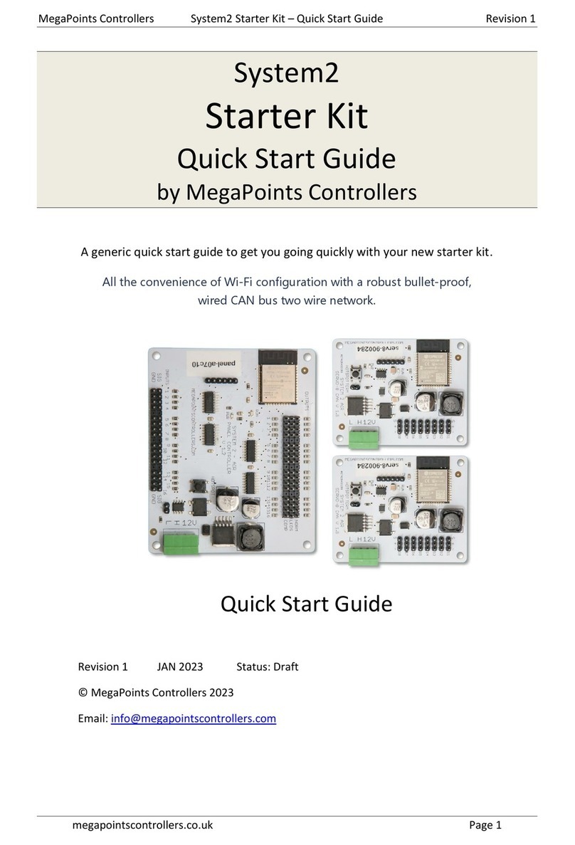
MegaPoints Controllers System2 Starter Kit Service manual

MegaPoints Controllers System2 Panel Controller User Reference Revision 1
megapointscontrollers.co.uk Page 1
System2
Panel Controller User
Reference
by MegaPoints Controllers
Sixteen input and sixteen output mimic panel controller for your model railway.
All the convenience of Wi-Fi configuration with a robust bullet-proof,
wired CAN bus two wire network.
User Guide
Revision 1 JAN 2023 Status: Draft
© MegaPoints Controllers 2023
Email: info@megapointscontrollers.com

MegaPoints Controllers System2 Panel Controller User Reference Revision 1
megapointscontrollers.co.uk Page 2
Table of contents
What is System2 Air? ..............................................................................................................................3
How to use this document......................................................................................................................3
System2 Panel Controller........................................................................................................................4
Introduction ........................................................................................................................................4
First use...............................................................................................................................................5
Network cabling..................................................................................................................................6
Getting your first board on your local Wi-Fi network.........................................................................7
Admin Interface ..................................................................................................................................9
Board Location..................................................................................................................................10
V-Ports...................................................................................................................................................12
Input Ports ........................................................................................................................................12
Input Type.........................................................................................................................................13
RGB Configuration.............................................................................................................................14
Output Ports .....................................................................................................................................14
Board level configuration......................................................................................................................14
EasyConfig setting.............................................................................................................................14
Locate Board .....................................................................................................................................16
CAN ID management.........................................................................................................................18
Wi-Fi credential sharing....................................................................................................................21
Actions ..................................................................................................................................................22
Reset to defaults...............................................................................................................................23
Save Changes ....................................................................................................................................24
Reload Values....................................................................................................................................24
Erase WiFi Credentials ......................................................................................................................25
Update Firmware..............................................................................................................................25
Reboot...............................................................................................................................................27
Reload Page.......................................................................................................................................28
Documentation .................................................................................................................................28
Network Monitor..............................................................................................................................28
Status area ............................................................................................................................................31
Board Type (1)...................................................................................................................................31
SW Rev (2).........................................................................................................................................32
Templates (3) ....................................................................................................................................32
IP Address (4) ....................................................................................................................................32
Board Name and serial (5) ................................................................................................................32
SSID(6)...............................................................................................................................................32
In conclusion .........................................................................................................................................32
Contacting us ........................................................................................................................................33

MegaPoints Controllers System2 Panel Controller User Reference Revision 1
megapointscontrollers.co.uk Page 3
What is System2 Air?
System2 is our new generation of model railway accessory bus products that feature our V-Port
protocol (virtual port) and can address up to 60,000 devices. You can scale an installation from a
single Servo-8 Controller (8 V-ports) right up to a huge layout as your needs grow. Flexibility is baked
in and as we announce new modules that will work right alongside other System2 modules.
The “Air” in System2 refers to how you configure the system. It’s done wirelessly using Wi-Fi. This
means you can configure a device using your PC, tablet or phone and replaces the need for buttons,
flashing lights and extension cables to reach under baseboard locations.
We use Wi-Fi for configuration and a CAN network for data. This offers high speed, low latency and
above all else reliability. You can even shut down the Wi-Fi network when your configuration is
complete making your system secure and robust. It’s not required for operation at all.
Software for all System2 Air modules can be updated over the air if your network allows Internet
access. A single button push is all that’s needed to download and install the latest version. This
means as new ideas and features are introduced everyone gets to benefit from them. You can even
see the changes that have been introduced since your last update and choose whether to install or
not. You won’t get nagging reminders to update. It’s flexible and entirely up to you when or if you
decide to do it.
System2 has been real world tested on some of the largest exhibition model railway layouts in the
UK for over a year before launching, so you can be confident it’s fit for your needs and fit for
purpose.
Each of our System2 boards has the administrative core baked in. You can connect to any board’s
admin web page and from there manage your entire network. There’s no central point of control (or
failure) as they are all peers in their own right.
We use standard web protocols for configuration so that your browser can connect and perform all
administrative tasks without requiring any special apps and app permissions. This leaves you in
control of your network.
System2 Air, for the smallest to the largest layouts and everything in between.
In order to use System2 you’ll need a Wi-Fi router configured for DHCP with optional Internet access.
This is the standard router configuration as supplied by your Internet Service Provider.
Designed and manufactured in Cheshire, England.
How to use this document
Treat this guide as a reference. All settings are documented and examples given where appropriate.
It is designed to accompany the System2 Air –Panel Controller video that will demonstrate all the
functions and use cases.

MegaPoints Controllers System2 Panel Controller User Reference Revision 1
megapointscontrollers.co.uk Page 4
System2 Panel Controller
Introduction
The System2 Panel Controller is a 16 input and 16 output device
primarily suited to driving mimic panels on System2 networks. It
features a Wi-Fi based intuitive configuration from the comfort of
your PC, tablet or phone.
Each input channel is individually configurable for:
oSwitch type
Push to make
Toggle
Block Detector
Points Position Sensor
oLatching time (delay)
oRGB colour
oInvert the switch logic
Each output channel can:
oDrive single and dual LEDs
oReverse its output
You will also need:
12 Volt DC regulated power supply.
o500 mA per Panel Controller.
Network cable (twisted pair).
oTelephone cable
oAlarm cable
oSuch as CW1109B/Y supplied by CPC/Farnell . See website for cable links. Non
twisted pair cable is OK for testing purposes, not for installation.
To use the network features of this board you will require:
A Wi-Fi Router that is configured for:
oDHCP (default enabled on most routers)
oAn active internet connection (only required for software updates).
A current browser that supports HTML5.
This is a 12 Volt device and
should be connected to a
minimum of 2 Amp
regulated power supply.
MegaPoints Controllers use
static sensitive components
that must be handled with
care.
Avoid touching any
components or the circuit
printed on the bottom of
the board.
Avoid placing the board on
any metallic surfaces
including track.
DO NOT connect any part
of this device directly to
your track bus.

MegaPoints Controllers System2 Panel Controller User Reference Revision 1
megapointscontrollers.co.uk Page 5
First use
See the image below for connection details.
Connect each board to a 12 Volt regulated power supply, minimum 500 mA per Panel
Controller.
Connect the network cable to the two screw terminals. Observe the ‘H’ and ‘L’ terminals.
Ensure all the ‘H’ and ‘L’ wires connect to each other respectively.
If your board was part of a starter kit it will be configured as EasyConfig board 1.
Connect an LED cable pair to output #1 ensuring the black lead is toward the outer edge.
Connect a button lead to input #1 ensuring the black lead is toward the outer edge.

MegaPoints Controllers System2 Panel Controller User Reference Revision 1
megapointscontrollers.co.uk Page 6
Network cabling
You can fit the termination jumpers to the first and last board on your network if not already fitted
(see above two diagrams).
See the above diagram for network cabling. All cables should be a twisted pair signal cable. Fit any
termination jumpers (supplied as part of a starter kit) to the boards at the ends of the network for a
maximum of two jumpers per network.
You can use droppers to a main bus much like DCC or connect boards to each other in daisy chain
fashion. Ensure the CAN-H and CAN-L connects to the same terminal in all cases.

MegaPoints Controllers System2 Panel Controller User Reference Revision 1
megapointscontrollers.co.uk Page 7
Getting your first board on your local Wi-Fi network
The very first board on from your System2 Air should be configured for your Wi-Fi. This will allow
you to connect and adjust the board settings and download future software. The examples below
are from a servo8 board. The hotspot for a panel controller will be “panel-xxxxxx” where the x’s are
your devices serial number.
Connect all boards of your starter kit to power and cable the CAN network prior to commencing.
Broadly speaking, here’s how to connect to your first board to Wi-Fi. Apply 12 VDC regulated power
to all starter kit System2 boards.
Observe the RUN LED flashing about once per second.
Press and hold the HOTSPOT button for 1 second; observe the RUN LED flash rate increase
to double.
From your phone, tablet or other Wi-Fi device scan for Wi-Fi networks and locate the
hotspot network for the panel controller (it will be the device name/serial number on the
sticker) such as “serv8-xxxxxx”. See above Servo-8 photo for example.
Connect to the devices hotspot network. You may receive a warning stating this network
does not connect to the Internet. This is normal.
Enter the address “192.168.4.1/admin” in your browser (screenshot below) on your phone
or tablet browser.
Enter the network name (SSID) and password for your local network. Note case sensitivity
(screenshot below). Note the IP Address field (1) is blank indicating no network connectivity.

MegaPoints Controllers System2 Panel Controller User Reference Revision 1
megapointscontrollers.co.uk Page 8
After saving (Submit button), reload the page and get the IP address (3). You may observe a
form resubmission confirmation (2). Select OK or Continue. Make a note of the IP address
(3). If you don’t see an IP address then the device has not connected to your network. Enter
the network name and password again and retry.
The IP address is assigned by your network and will probably be different from the example
here.
Revert your phone or table back to your own network.
On a computer or other device connected to your network direct your browser to the IP
address or hostname from the above step. You will see a web page similar to the example
below (next page).
You can now automatically connect every board on your network to your Wi-Fi by pressing the
“Share Wi-Fi credentials” button. YOU ONLY PERFORM THE ABOVE PROCESS ONCE ON YOUR FIRST
BOARD. All subsequent boards will pick up the Wi-Fi credentials from your first board.
Every board that is connected to your CAN bus will report in on the main status page. From there
you can see all boards IP addresses, board types and installed software versions.

MegaPoints Controllers System2 Panel Controller User Reference Revision 1
megapointscontrollers.co.uk Page 9
Admin Interface
The admin web page is shown on the page below. It is the place where you will change any settings
for the Panel Controller. Each board on the System2 network has its own management web page
and is unique to the board type and features.
From the main page you can see the following information:
Device name and serial number
Device picture

MegaPoints Controllers System2 Panel Controller User Reference Revision 1
megapointscontrollers.co.uk Page 10
User definable text description or location
Input port configuration including:
oV-Port
oPositive latch time (milliseconds)
oInput type
oInvert
oRGB settings for RGB LEDs (requires RGB output board)
Output port configuration
oV-Port
oInvert
EasyConfig (if selected)
Locate Board: Will cause the LED on the selected board to flash fast helping you to locate the
board if you have many.
Auto CAN ID. You can override the CAN ID if required.
Share and revoke Wi-Fi credentials with all boards on the network
Control buttons (shown in blue text) to:
oReset the board
oSave changes you’ve made
oReload changes (resyncs the web page with board)
oErase this boards Wi-Fi credentials (will immediately leave the network)
oSelect the firmware update (requires internet connection)
oReboot the board (throws out any unsaved changes if you made a mess)
oReload the web page
oLink to online documentation and support videos
oA CAN network monitor (for those who prefer watching network packets to trains).
The next line shows:
oProduct name (Panel Controller)
oSoftware version
oTemplates version (should usually match the software version)
oThe local IP address
oThe device network name and serial number
oThe Wi-Fi name you are connected to (SSID)
The last item is a status log (light yellow background). This provides a real time status such as
up to date software, or boards joining the network, whether you saved (or should) save your
changes etc.
Board Location
The board location field (top right) should be used to enter meaningful information to help you
locate a specific board. We are planning an update for this feature in a future release that will
display the first few characters as part of a report when you request all boards to report in (covered
later in this document).
We suggest you begin the text with the most meaningful information such as a baseboard number
or location for example:

MegaPoints Controllers System2 Panel Controller User Reference Revision 1
megapointscontrollers.co.uk Page 11
Suggested entry types
B2 Fiddle Yard
12 Station throat
A3 Scenic
Avoid
Baseboard B2
Main approach on the left
The location will be added to reports in a future software update. This will be truncated to the first
few characters (report formatting) so it’s much more useful to state a location such as “B2”or“C12”
than the word “Baseboard”.

MegaPoints Controllers System2 Panel Controller User Reference Revision 1
megapointscontrollers.co.uk Page 12
V-Ports
System2 is an event driven system. This means when a button is pressed an event is generated on
the network. This event is visible to all connected boards and will be acted on by those boards
listening for that event.
At the heart of the system is the “V-Port” or virtual port. The system will allow V-Ports in the range 1
–60,000 which should be big enough for the largest and most sophisticated layouts.
When you set a V-Port address under the “V-Port” column you are saying that the servo is to listen
for events on this V-Port and take commanded action if appropriate.
A corresponding V-Port should be configured on an output channel such as a Panel Controller, PC or
DCC interface.
Input Ports
Refer to the above diagram when reading this section.
Input ports (physical connections to the board such as a switch) are grouped on the leftmost
columns. Here is a description of the columns:

MegaPoints Controllers System2 Panel Controller User Reference Revision 1
megapointscontrollers.co.uk Page 13
Phys Port
Physical Port on the device. Matches the port numbers along the bottom of the
device.
V-Port
Virtual port the input is assigned to. If physical port 6 has a pushbutton attached
the above configuration will trigger an event on V-Port 6 as defined in the V-Port
column. Range is 1 –60,000.
Latch (ms)
Latch time in milliseconds. We use the latch time to denounce switch contacts or
sensors. The latch time locks a switch closed for the latching time. Default values
are automatically loaded (see next section for details). Range is 10 –60,000.
Input Type
This tells the panel controller the input type such as push to make button
(default), toggle switch, occupancy sensor, points position sensor. Detailed
examples in the next section.
Invert
Reverses the input logic. For push to make type it is ignored, for toggle switches
OFF becomes ON and vice versa. For sensors it reverses the input.
RGB
This will configure the input to send RGB values (Red, Green or Blue) to a V-Port
with RGB LEDs attached. See the release schedule on the System2 website for
release dates. More details on how this operates in the next section. Each RGB
value is from 0 –255.
Colour
This will display for RGB colour for the respective channel.
B/G
Background/foreground colour.
Input Type
You can select the input type by selecting it from the drop down box (below).
The right image (above) shows the default latch times for each of the input types. These may be
overridden with values in the range 10 –60000 ms (hundredth of a second to 60 seconds).
A little creativity with these parameters can yield interesting results. For example if a push to make
button is attached to physical port and its input type is set to toggle switch and the latch time set to
30000 you will create an event when the button is pressed (switch something on) and 30 seconds
after releasing it will automatically switch off. This effectively creates a timer function to a
pushbutton.

MegaPoints Controllers System2 Panel Controller User Reference Revision 1
megapointscontrollers.co.uk Page 14
You could also use on an occupancy sensor where an event is triggered when a train enters a block
and stopped a set interval after it leaves.
RGB Configuration
The RGB section requires an RGB output board (not available at time of writing).
Each Red, Green or Blue column can have the values from 0 –255. The Colour column will show the
colour of the RGB values entered.
Background colours are written underneath foreground colours. This allows you to illuminate a route
automatically as read from a points position sensor, say in white and then impose a foreground
colour on top from a block occupancy detector.
In the image above you can see physical port 2 is triggering V-Port 2 with a white background colour
from a points position sensor.
Physical port 3 is triggered by an occupancy sensor. The Red value is 255 (maximum brightness) and
is illustrated under the Colour column. The B/G column indicates this is a foreground colour (default)
and will overwrite the background colour when set on. When off the RGB LEDs will revert to the
background colour (if set) or off.
Output Ports
The Panel Controller can drive a pair of LEDs that will alternate with each colour. When one is on,
the other will be off. The intended use it to indicate the direction of a set of points. Single LEDs can
also be connected to the output ports and display track occupancy or any other V-Port status.
When used in conjunction with a slow acting System2 motor driver board such as a servo8 the LED
pairs can be set to flash when the motor is running. See the respective System2 motor driver board
documentation for details.
Board level configuration
This section is common to all System2 boards and features examples from the servo8 driver.
EasyConfig setting
The power of System2 allows individual adjustment of every channel including the V-Port ranges.
This allows for maximum flexibility when required. To speed installation we’ve pre mapped the first
10 Panel Controller boards for you into a logical address space on the input V-Port and output V-

MegaPoints Controllers System2 Panel Controller User Reference Revision 1
megapointscontrollers.co.uk Page 15
Ports. This will preselect compatible addresses with other starter kit driver boards and get you up
and running quickly.
Refer to the screen shot below for a detailed explanation. Numbers in red circles relate to paragraph
number of text.
3
To change the EasyConfig for this board, select the board from the drop down.
1,2
Upon mousing over the drop down box (3) you will observe the greyed out
values in the green highlighted areas. This shows the values that are about to
be changed.
4
The EasyConfig board number 1 –10.
5
The first V-Port address of the configuration.

MegaPoints Controllers System2 Panel Controller User Reference Revision 1
megapointscontrollers.co.uk Page 16
After selecting EasyConfig Board 44 (49) you will observe the following:
1,2
Values have been loaded and background returns to normal white.
3
EasyConfig board selection you just made.
All changes you have made are instantly live and useable, however not saved. This is great for testing
and trying things out before committing. If you make a mess of things or want to revert you can
select the “Reboot” option. This will revert to the last saved settings.
You may observe two horizontal grey lines separating the Port Configuration above the text and
below the EasyConfig. With the exception of the Locate Board tick box everything in this section
relates to individual port configuration.
Locate Board
The Locate Board check box will cause two actions when selected.

MegaPoints Controllers System2 Panel Controller User Reference Revision 1
megapointscontrollers.co.uk Page 17
First, it will cause the flashing LED indicator on that board to flash rapidly. This helps locate and
identify the board if you have multiple boards in one location.
Second, it will request that all CAN connected boards report in with their stats, assigned IP address,
CAN ID, Board Type and software version.
The blue IP address in the Status Log area is clickable and will take you to the management screen
for that board.
Any boards not connected to the Wi-Fi will show an IP address of “0.0.0.0”.
The above example shows three boards on the network in addition to the Servo-8 board we are
issuing the commands from. In summary we have:
The servo-8 board we are connected to via the web browser.
2 x Panel Controller, ID’s 493 and 340 with their respective IP addresses showing they are connected
to Wi-Fi.
1 x Relay Driver, ID 800 with an unassigned IP address (all zeroes) indicating this is not connected to
your Wi-Fi.
Clicking the Locate Board checkbox again will remove the tick and stop the boards rapid flashing.
This is reset upon reboot.

MegaPoints Controllers System2 Panel Controller User Reference Revision 1
megapointscontrollers.co.uk Page 18
CAN ID management
The next area down on the main configuration page concerns network parameters. Refer to the
screenshot below and explanation text for details.
1
Auto CAN ID –Normally left selected (default). This will allow the board to
automatically assign its CAN address and if a duplicate is detected may
automatically reassign to a vacant address.
2
The current boards CAN ID. Showed greyed out if auto enabled (default).
Automatic range: The automatic range for the CAN ID is 1 –9999. If a duplicate is detected and Auto
CAN ID is enabled either this or the other board with a duplicate ID will seek out a vacant CAN ID and
update its configuration. When Auto CAN ID is selected do not expect CAN IDs to be persistent as
they can change without notice. System2 is designed with this in mind and the board CAN ID is not
relevant to operation.
The CAN specification requires all boards to have a unique CAN ID as part of the collision detection
mechanism. Forcing duplicates is a bad idea and will lead to data errors.
Manual CAN ID selection: We must ask why? There’s no possible benefit we can think of, so it’s
included for edge use cases. Not recommended to change this. Manual range is 1000 –1999.

MegaPoints Controllers System2 Panel Controller User Reference Revision 1
megapointscontrollers.co.uk Page 19
When reselecting Auto CAN ID, the current setting will remain until a collision is detected;
whereupon the software will automatically reassign the ID (see below).
If a duplicate ID is detected and the address manually configured you will observe a message in the
Status Log (example below) warning of the duplicate address and that auto change is disabled You
need to manually reconfigure this.

MegaPoints Controllers System2 Panel Controller User Reference Revision 1
megapointscontrollers.co.uk Page 20
With Auto CAN ID enabled the message is slightly different (see below):
The CAN ID was automatically changed to an unused ID. When the board is rebooted or the web
page refreshed the CAN ID field will update to the new value.
Other manuals for System2 Starter Kit
2
Table of contents
Other MegaPoints Controllers Computer Hardware manuals
Popular Computer Hardware manuals by other brands
Panasonic
Panasonic TY-FB10HMD - Monitor Terminal Expansion... Dimensions
ST
ST X-NUCLEO-OUT02A1 user manual
Thermalright
Thermalright Turbo Right 240 installation guide

Help Tech
Help Tech Handy Tech Active Star user manual

Cromemco
Cromemco ZPU instruction manual
HighPoint
HighPoint R1508 Quick installation guide
