MEGAREVO REVO Series User manual
Hybrid Inverter User Manual

contents
contents
1. Notes on this Manual....................................................................................................................................1
1.1 Scope of Validity..................................................................................................................................1
1.2 Target Group........................................................................................................................................1
1.3 Symbols Used.......................................................................................................................................1
2. Safety ..................................................................................................................................................................2
2.1 Important Safety Instructions..........................................................................................................2
2.2 Notes on this Manual Explanation of Symbol...........................................................................6
2.3 CE Directives .........................................................................................................................................7
3. Introduction......................................................................................................................................................8
3.1 Basic features
......................................................................................................................................8
3.2 Work Modes ...................................................................................................................................... 10
3.3 Dimension...........................................................................................................................................11
3.4 Terminals of Hybrid inverter
.......................................................................................................12
4. Technical Data .............................................................................................................................................. 14
5. Installation......................................................................................................................................................17
5.1 Check for Physical Damage..........................................................................................................17
5.2 Packing List......................................................................................................................................... 17
5.3 Mounting ............................................................................................................................................18
6. Electrical Connection ..................................................................................................................................21
6.1 PV connection................................................................................................................................... 21
6.2 Grid Connection ...............................................................................................................................23
6.3 EPS Connection (apply to I Version and E Version only).................................................... 25
6.4 Battery Connection.......................................................................................................................... 29
6.5 CT Connection and Phase instruction.......................................................................................31
6.6 DRM Connection (Function temporarily retained)................................................................ 33
6.7 WiFi Connection(optional) ............................................................................................................34
6.8 GPRS Connection(optional).......................................................................................................... 35
6.9 Inverter Manipulation .....................................................................................................................36
7. Setting..............................................................................................................................................................37
7.1 Control Panel.....................................................................................................................................37
7.2 Instructions for LED Indicator ......................................................................................................38
7.3 Instructions for the use of three modes................................................................................... 39
8. LCD Operation.............................................................................................................................................. 41
8.1 LCD Interface.....................................................................................................................................41
8.2 Setting.................................................................................................................................................. 45
8.3 INQUIRE...............................................................................................................................................55
8.4 STATISTIC............................................................................................................................................57
9. Fault diagnosis and solutions ..................................................................................................................58

Notes on this Manual
1/ 61
1. Notes on this Manual
1.1 Scope of Validity
This manual is an integral part of REVO series hybrid inverter, It describes the assembly,
installation, commissioning, maintenance and failure of the product. Please read it
carefully before operating.
R6KH3
R8KH3
R10KH3
R12KH3
R15KH3
N
aming rules , For example:R8KH3
“R” means “REVO series”.
“8k” means “output power 8kW ”.
“H” means “Battery High Voltage”.
“3” means “Output three-phase .
Store this manual where it will be accessible at all times.
1.2Target Group
This manual is for qualified electricians. The tasks described in this manual only can be
performed by qualified electricians.
1.3Symbols Used
The following types of safety instructions and general information appear in this
document as described below:
“Danger” indicates a hazardous situation which, if not avoided, will result in death or serious injury.
“
Warning” indicates a hazardous situation which, if not avoided, could result in death or serious injury.
“Caution” indicates a hazardous situation which, if not avoided, could result in minor or moderate
injury.
Note!
“ Note” provides tips that are valuable for the optimal operation of our product.

Safety
2/ 61
2. Safety
2.1 Important Safety Instructions
Danger!
Danger to life due to high voltages in the inverter ! All work must be carried
out by qualified electrician
The appliance is not to be used by children or persons with reduced physical sensory or
mental capabilities, or lack of experience and knowledge, unless they have been given
supervision or instruction.
During operation, the upper of the enclosure and the enclosure body may become hot.
Only touch the lower enclosure lid during operation.
Do not stay closer than 20 cm to inverter for any length of time.
Note!
Comply with the local requirements for grounding the PV modules and the PV generator. It
is recommends connecting the generator frame and other electrically conductive surfaces in
a manner which ensures continuous conduction and ground these in order to have optimal
protection of system and persons.
Warning!
Ensure input DC voltage ≤Max. DC voltage .Over voltage may cause permanent damage to
inverter or other losses, which will not be included in warranty!
Warning!
Authorized service personnel must disconnect both AC and DC power from inverter before
attempting any maintenance or cleaning or working on any circuits connected to inverter.
Warning!
Safety
3/ 61
•Prior to the application, please read this section carefully to ensure correct and safe
application. Please keep the user manual properly.
•Accessories only together with the inverter shipment are recommend here .other- wise
may result in a risk of fire, electric shock, or injury to person.
•Make sure that existing wiring is in good condition and that wire is not undersized.
•Do not disassemble any parts of inverter which are not mentioned in installation guide. It
contains no user-serviceable parts. See Warranty for instructions on obtaining service.
Attempting to service the inverter yourself may result in a risk of electric shock or fire and
will void your warranty.
•Keep away from flammable, explosive materials to avoid fire disaster.
•The installation place should be away from humid or corrosive substance.
•Authorized service personnel must use insulated tools when installing or working with
this equipment.
•PV modules shall have an IEC 61730 class A rating.
•Never touch either the positive or negative pole of PV connecting device. Strictly prohibit
touching both of them at the same time.
•The unit contains capacitors that remain charged to a potentially lethal voltage after the
MAINS , battery and PV supply has been disconnected.
•Hazardous voltage will present for up to 5 minutes after disconnection from power supply.
•CAUTION-RISK of electric shock from energy stored in capacitor, Never operate on the
inverter couplers, the MAINS cables, Battery cables, PV cables or the PV generator when
power is applied. After switching offthe PV , battery and Mains, always wait for 5minutes
to let the intermediate circuit capacitors discharge before unplug DC ,battery plug and
MAINS couplers.
•When accessing the internal circuit of inverter, it is very important to wait 5 minutes before
operating the power circuit or demounting the electrolyte capacitors inside the device.
Do not open the device beforehand since the capacitors require time sufficiently
discharge!
•Measure the voltage between terminals UDC+ and UDC- with a multi-meter(impedance
at least 1Mohm) to ensure that the device is discharged before beginning work (35VDC)
inside the device.
Surge protection devices (SPDs) for PV installation
Lightning will cause a damage either from a direct strike or from surges due to a nearby
Warning!
Warning!
Over-voltage protection with surge arresters should be provided when the PV power
system is installed.
The grid connected inverter is not fitted with SPDs in both PV input side and MAINS
side.

Safety
4/ 61
strike.
•Induced surges are the most likely cause of lightning damage in majority or installations,
especially in rural areas where electricity is usually provided by long overhead lines. Surge
may be included on both the PV array conduction and the AC cables leading to the
building.
•Specialists in lightning protection should be consulted during the end use application.
•Using appropriate external lightning protection, the effect of a direct lightning strike into
a building can be mitigated in a controlled way, and the lightning current can be
discharged into the ground.
•Installation of SPDs to protect the inverter against mechanical damage and excessive
stress include a surge arrester in case of a building with external lightning protection
system (LPS) when separation distance is kept.
•To protect the DC system, surge suppression device (SPD type2) should be fitted at the
inverter end of the DC cabling and at the array located between the inverter and the PV
generator, if the voltage protection level (VP) of the surge arresters is greater than 1100V,
an additional SPD type 3 required for surge protection for electrical devices.
•To protect the AC system, surge suppression devices (SPD type2) should be fitted at the
main incoming point of AC supply (at the consumer’s cutout), located between the
inverter and the meter/distribution system; SPD (test impulse D1) for signal in according
l to EN 61632-1.
•All DC cables should be installed to provide as short a run as possible, and positive and
negative cables of the string or main DC supply should be bundled together. Avoiding
the creation of loops in the system.
•Spark gap devices are not suitable to be used in DC circuits once conducting, they won’t
stop conducting until the voltage across their terminals is typically more than 30 volts.
Anti-Islanding Effect
•Islanding effect is a special phenomenon that grid-connected PV system still supply
power to the nearby grid when the voltage loss is happened in the power system. It is
dangerous for maintenance personnel and the public. Revo-Hybrid series inverter
provide Active Frequency Drift(AFD) to prevent islanding effect.
PE Connection and Leakage Current
•The end-use application shall monitor the protective conductor by residual current
operated protective device (RCD) with rated fault current Ifn≤240mA which automatically
disconnects the device in case of a fault.
The device is intended to connect to a PV generator with a capacitance limit of about
700nf.
•
Incorrect grounding can cause physical injury, death or equipment malfunction and
increase electromagnetic.
•
Make sure that grounding conductor is adequately sized as required by safety
Warning!

Safety
5/ 61
regulations.
•
Do not connect the ground terminals of the unit in series in case of a multiple
installation. This product can cause current with a DC component, Where a residual
current operated protective (RCD) or monitoring (RCM) device is used for protection
in case of direct or indirect contact, only an RCD or RCM of type B is allowed on the
supply side of this product.
For United Kingdom
•
The installation that connects the equipment to the supply terminals shall comply with
the requirements of BS 7671.
•
Electrical installation of PV system shall comply with requirements of BS 7671 and IEC
60364-7-712.
•
No protection settings can be altered.
•
User shall ensure that equipment is so installed, designed and operated to maintain at
all times compliance with the requirements of ESQCR22(1)(a).
For Australia and New Zealand
•
Electrical installation and maintenance shall be conducted by licensed electrician and
shall comply with Australia National Wiring Rules.
Battery Safety Instructions
•
Revo hybrid Series inverter should be worked with high voltage battery, for the specific
parameters such as battery type, nominal voltage and nominal capacity etc., please
refer to section 4.
•
As accumulator batteries may contain potential electric shock and short-circuit current
danger, to avoid accidents that might be thus resulted, the following warnings should
be observed during battery replacement:
1: Do not wear watches, rings or similar metallic items.
2: Use insulated tools.
3: Put on rubber shoes and gloves.
4: Do not place metallic tools and similar metallic parts on the batteries.
5: Switch off load connected to the batteries before dismantling battery connection
terminals.
6: Only personal with proper expertise can carry out the maintenance of accumulator
batteries.
Safety
6/ 61
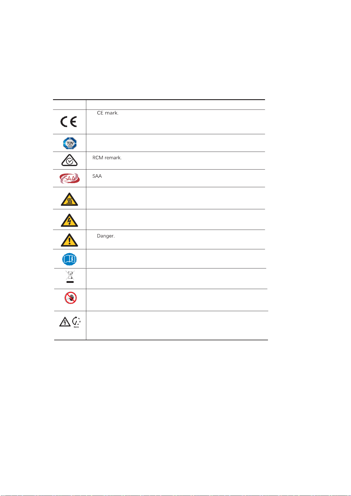
2.2 Notes on this Manual Explanation of Symbol
This section gives an explanation of all the symbols shown on the inverter and on the type
label.
Symbols on the Type Label
Symbol
Explanation
The inverter complies with the requirements of the applicable CE
TUV
certification.
Beware of hot surface.
The inverter can become hot during operation. Avoid contact during operation.
Danger of high voltages.
Danger to life due to high voltages in the inverter!
Risk of electric shock!
Observe enclosed documentation
The inverter can’t be disposed together with the household waste. Disposal
information can be found in the enclosed documentation
。
Do not operate this inverter until it is isolated from battery ,mains and on-site PV
generation suppliers.
Danger to life due to high voltage.
There is residual voltage existing in the inverter after powering off.
which needs 5 min to discharge.
Wait 5 min before you open the upper lid or the DC lid.

Safety
7/ 61
2.3 CE Directives
This chapter follows the requirements of the European low voltage directives,
which contains the safety instructions and conditions of acceptability for the
endues system, which you must follow when installing, operating and servicing
the unit. If ignored, physical injury or death may follow, or damage may occur
to the unit. Read this before you work on the unit. If you are unable to
understand the dangers, warnings, cautions or instructions please contact an
authorized service dealer before installing. Operating and servicing the unit.
The Grid connected inverter meets the requirement stipulated in Low Voltage
Directive (LVD) 2014/35/EU and Electromagnetic Compatibility (EMC) Directive
2014/30/EU. The unit is based on: EN 62109-1:2010; EN 62109-2:2011; IEC
62109-1(ed.1); IEC62109-2(ed.1); EN 61000-6-3:2007+A: 2011; EN 61000-6-
1:2007;
EN 61000-6-2:2005;
In case of installation in PV system, startup of the unit (i.e. start of designated
operation) is prohibited until it is determined that the full system meets the
requirements stipulated in EC Directive (2014/35/EU, 2014/30/EU, etc.),The
grid connected inverter leave the factory completely connecting device and
ready for connection to the mains and PV supply ,the unit shall be installed in
accordance with national wiring regulations. Compliance with safety
regulations depends upon installing and configuring system correctly,
including using the specified wires.
The system must be installed only by professional assemblers who are
familiar with requirements for safety and EMC. The assembler is responsible
for ensuring that the end system complies with all the relevant laws in the
country where it is to be used.
The individual subassembly of the system shall be interconnected by means
of the wiring methods outlined in national/international such as the national
electric code (NFPA) No.70 or VDE regulation 0107.
Introduction
8/ 61
3. Introduction
3.1 Basic features
Revo Hybrid Series is a high-quality inverter which can convert solar energy to AC energy
and store ene
rgy into battery.
The inverter can b
e used to optimize self-consumption, store in the battery for future
use or feed in to public grid. Work mode depends on PV energy and user’s preference. It
can provide power for emergency use during the grid lost by using the energy from
battery and inverter generated from PV.
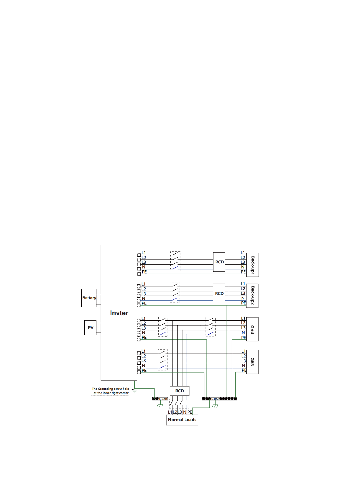
System Diagram
Revo Hybrid Series is designed with two EPS versions for customer to choose based on
the local rules.
E Version applies to the wiring rules that requires the Live line and N (Neutral) line of
EPS must be disconnected with the Live line and N (Neutral) line of grid (applies to
most countries).

Introduction
9/ 61
I Version applies tothe wiring rules that requires N (Neutral) line of alternative supply must
NOT be isolated or switched (applies to wiring rules AS/NZS_3000:2012 for Australia
and New Zealand).
Note!
Please control the home loads, and make sure it’s within the “EPS output rating” under
EPS mode, otherwise the inverter will Shut down with an “overload fault” warning.
Please confirm with the mains grid operator whether there is any special regulations for
grid connection.
The wiring diagram is for reference only, and the complete electrical connection shall
meet the requirements of local regulations.
Do not misconnect the phase sequence. Otherwise, the inverter cannot run normally.

Introduction
10 / 61
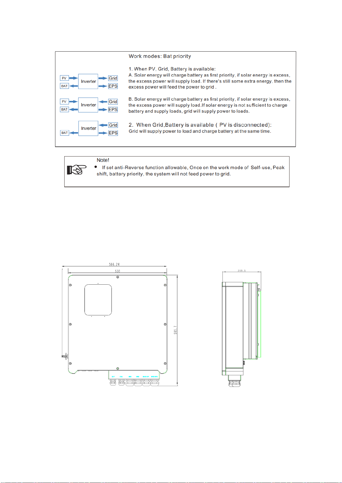
3.2 Work Modes
Inverter provides multiple work modes based on different requirements.
synonymy:Back-UP/EPS/LOAD
Introduction
11 / 61
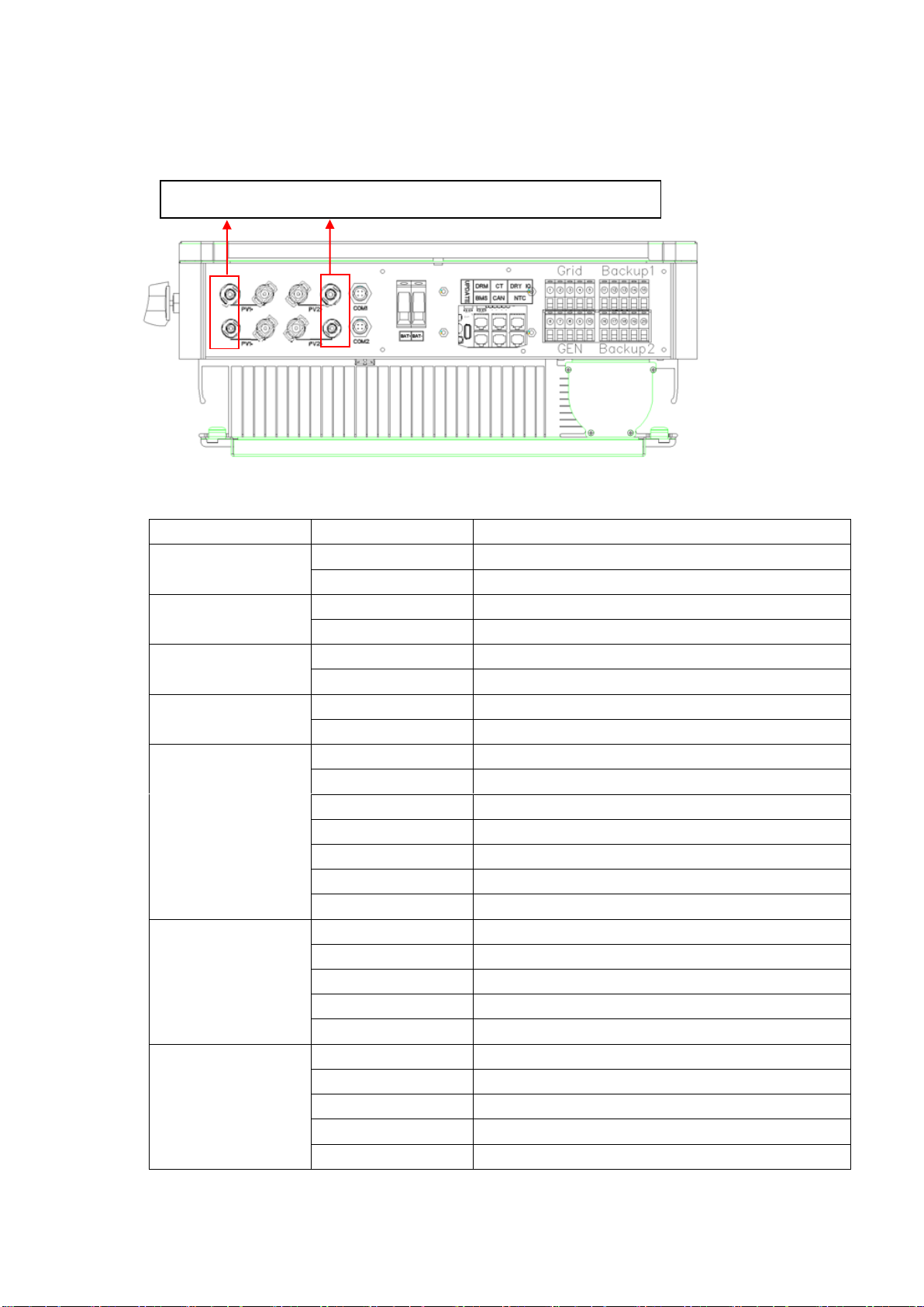
3.3 Dimension
Unit: mm
Introduction
12 / 61
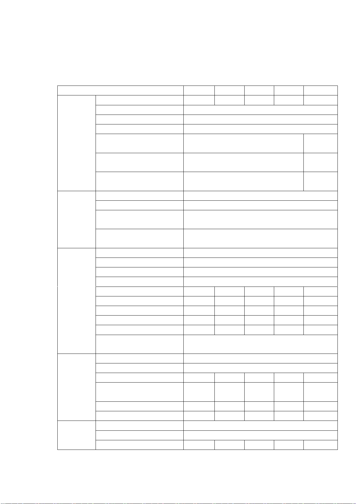
3.4 Terminals of Hybrid inverter
Function
label
Description
PV string 1 Input port
PV1+
PV string 1 positive input
PV1-
PV string 1 negative input
PV string 2 Input port
PV2+
PV string 2 positive input
PV2-
PV string 2 negative input
Communication interface
COM1
GPRS port(optional)
COM2
WIFI port (optional)
BAT Port
BAT+
Battery Positive input
BAT-
Battery negative input
signal line interface
UPDATE
Upgrading software Ports
DRM
Function temporarily retained
CT
Connect to CT (current transformer)
DRY IO
dry contact
BMS
BMS communication to Battery
CAN
CAN communication
NTC
NTC detection
Grid
①
Grid line A phase
②
Grid line B phase
③
Grid line C phase
④
Grid line null line
⑤
Grid line ground electrode
GEN
(Diesel generator function is
unreleased currently)
⑥
A phase
⑦
B phase
⑧
C phase
⑨
null line
⑩
ground electrode
R15KH3 tthis plugs used , other inverter models plugs are reserved.

Introduction
13 / 61
Backup1
⑪
Backup1 line A phase
⑫
Backup1 line B phase
⑬
Backup1 line C phase
⑭
Backup1 line null line,
⑮
Backup1 line ground electrode
Backup2
⑯
Backup2 line A phase
⑰
Backup2 line B phase
⑱
Backup2 line C phase
⑲
Backup2 line null line,
⑳
Backup2 line ground electrode
Installation
14 / 61
4. Technical Data
Model
R6KH3
R8KH3
R10KH3
R12KH3
R15KH3
PV Input
Max. PV array power
9kW
12kW
15kW
18kW
22.5kW
Max. input voltage
1000 V
MPPT voltage range
180 V ~ 850 V
Min. input voltage / start voltage
125V/180V
No. of independent MPPT trackers
/ strings per MPPT input
2 / (1/1)
2/(2/2)
Max. input current per MPPT
tracker
13 A/13A
20A/20A
Max. short-circuit current per MPPT
tracker
16A/16A
30A/30A
Battery
Battery type
Lithium and Lead Acid Battery
Battery voltage range
125V ~ 600 V
Max. charging current / Max.
discharging current
50 A / 50A
Rated. charging current / Rated.
discharging current
40A/40A
AC output
Nominal AC voltage
3W+N+PE, 220 / 380 V; 230 / 400 V; 240 / 415 V
AC voltage range
360V~440V
Rated AC grid frequency
50 Hz / 60 Hz
AC grid frequency range
50 Hz±5Hz / 60 Hz±5Hz
Rated active power
6 kW
8 kW
10 kW
12 kW
15 kW
Rated apparent power
6kVA
8kVA
10kVA
12kVA
15kVA
Max. apparent power
6.6kVA
8.8kVA
11 VA
13.2kVA
16.5kVA
Rated grid output Current (@400V)
8.7A
11.5A
14.4A
17.3A
21.7 A
Max. grid output current
9.5A
12.7A
15.9A
19.1A
23.8A
Harmonics THDI (@ Nominal
power)
< 3%
AC input
Rated grid voltage
3W+N+PE, 220 / 380 V; 230 / 400 V; 240 / 415 V
Rated grid frequency
50Hz / 60Hz
Rated apparent power
12 kW
16 kW
20 kW
24 kW
30 kW
Max. input apparent power from
grid
13.2kVA
17.6kVA
22kVA
26.4kVA
33.3kVA
Rated input current from grid
17.3A
23.1 A
28.9A
34.7A
43.4A
Max. input current from grid
19A
25.5 A
31.9A
38.2 A
47.6A
BACKUP
output
Nominal output voltage
3W+N+PE, 220 / 380 V; 230 / 400 V; 240 / 415 V
Nominal output frequency
50 Hz / 60 Hz
Rated apparent power
6kVA
8kVA
10kVA
12kVA
15kVA

Installation
15 / 61
Model
R6KH3
R8KH3
R10KH3
R12KH3
R15KH3
Max. output apparent power
6.6kVA
8.8kVA
11kVA
13.2kVA
16.5kVA
Peak output apparent power
6.6kVA
8.8kVA
11kVA
13.2kVA
16.5kVA
Rated Current (@400V)
8.7A
11.5 A
14.4A
17.3 A
21.7A
Max. output current
9.5A
12.7A
15.9A
19.1A
23.8A
Max. switch time
≤20ms
Output THDI (@ Linear load)
<2%
Efficiency
MPPT efficiency
≥99.5%
Max efficiency
97.90%
97.90%
98.20%
98.20%
98.50%
Euro efficiency
97.20%
97.20%
97.50%
97.50%
97.6%
Max. battery to load efficiency
97.50%
97.50%
97.50%
97.60%
97.80%
Safety
protection
DC-side disconnection device
●
PV string reverse polarity
protection
●
All-pole sensitive residual current
monitoring unit
●
Anti-islanding protection
●
AC output over current protection
●
AC output short circuit current
protection
●
AC over voltage protection
●
Protection class (as per IEC 62109-
1)
I
overvoltage category (as per IEC
62109-1)
AC: III; DC: II
General
data
Power factor at rated power /
adjustable displacement
0.99 / 0.8 leading to 0.8 lagging
Dimensions (W / H / D)
530 / 560 / 220 mm
Device weight
30 kg
31 kg
31kg
33 kg
34 kg
Installation
Wall-mounted
Operating temperature range
-25 °C~+60 °C
Noise emissions (typical)
< 35 dB(A)
Standby consumption
< 3 W
Cooling concept
Natural convection
Ingress protection rating (as per IEC
60529)
IP65
Climatic category (according to IEC
60721-3-4)
4K4H
Max. permissible value for relative
humidity
0~95%
(non-condensing)

Installation
16 / 61
Model
R6KH3
R8KH3
R10KH3
R12KH3
R15KH3
Max. operating altitude
4000m (>2000m power derating)
Features
Inverter topology (Solar/ battery)
Transformer less / Transformer less
User interface
LED & App
Communication with BMS
RS485 / CAN
Communication with meter
RS485
Communication with portal
WIFI stick
Integrated power control / Zero
export control
●/ ●
Standard
Compliance
Safty
EN 62109-1, EN 62109-2
EMC
IEC 61000-6-1/-2/-3/-4, IEC 61000-3-11, IEC61000-3-12

Installation
17 / 61
5. Installation
5.1Check for Physical Damage
Make sure the inverter is intact during transportation. If there is any visible damage, such as
cracks, please contact your dealer immediately.
5.2Packing List
Open the package and take out the product, please check the accessories first. The packing
list shown as below.
Object
Description
A
Inverter
B
Bracket
C
Expansion screws and pan-head screws
D
PV connectors (2*positive, 2*negative)
E
WIFI module (optional)
F
GPRS module (optional)
G
User manual
H
current transformer(CT)

Installation
18 / 61
5.3 Mounting
Installation Precaution
REVO Series inverter is designed for outdoor installation (IP 65). Make sure the installation
site meets the following conditions:
•
Not in direct sunlight.
•
Not in areas where highly flammable materials are stored.
•
Not in potential explosive areas.
•
Not in the cool air directly.
•
Not near the television antenna or antenna cable.
•
Not higher than altitude of about 2000m above sea level.
•
Not in environment of precipitation or humidity (>95%).
•
Under good ventilation condition.
•
The ambient temperature in the range of -20℃ to +60℃.
•
The slope of the wall should be within ± 5°.
•
The wall hanging the inverter should meet conditions below:
1. solid brick/concrete, or strength equivalent mounting surface;
2. Inverter must be supported or strengthened if the wall’s strength isn’t enough
(such as wooden wall, the wall covered by thick layer of decoration)
Please AVOIDE direct sunlight, rain exposure, snow laying up during installation
and operation.
This manual suits for next models
5
Table of contents
Other MEGAREVO Inverter manuals


Popular Inverter manuals by other brands

APsystems
APsystems YC500A-EU Quick installation guide

FRONIUS
FRONIUS Symo Hybrid 3.0-3-S operating instructions

APsystems
APsystems YC500A Installation & user manual

Data Video
Data Video TC-200 quick start guide

Alfain
Alfain PEGAS 160 T PULSE HF Service manual

APsystems
APsystems YC1000-3-220 Quick installation guide

Tripp Lite
Tripp Lite PowerVerter 200712159 owner's manual

MQ Power
MQ Power WHISPERWATT DCA-36SPX Operation and parts manual

FRONIUS
FRONIUS Symo GEN24 3.0 Plus quick start guide

Tripp Lite
Tripp Lite PowerVerter APS1524 Features & specifications

Solark
Solark 5K-2P-N installation guide

Sun Power
Sun Power SPR-5200 Installation and operation manual


