MegaTech Solar series User manual
1
tech
36 00 5823 Issue 4
tech
Fitting and using the Megatech Solar unvented
mains pressure water heater
Solar
36005942 issue 4

2
2
techtech
Contents
SECTION PAGE
1 INTRODUCTION ........................................................................... 3
2 GENERAL REQUIREMENTS ...................................................... 4
3 INSTALLATION - GENERAL ......................................................... 6
4 INSTALLATION - SOLAR PRIMARY ............................................ 15
5 INSTALLATION - DIRECT UNITS ................................................. 16
6 INSTALLATION - AUXILLARY COIL (INDIRECT UNITS) ............ 18
7 COMMISSIONING ....................................................................... 23
8 USER INSTRUCTIONS................................................................ 25
9 MAINTENANCE ........................................................................... 27
10 FAULT FINDING & SERVICING .................................................. 29
11 DIMENSIONS & SPECIFICATIONS ........................................... 32
12 GUARANTEE ................................................................................ 35
13 CONTACTS ................................................................................... 36
Contents
Please read and understand these instructions before starting work.
The information contained in these instructions details how to connect
the Megatech Solar water heater to a solar primary circuit. Other
controls will be necessary to provide control over the primary circuit,
refer to the instructions supplied with the solar controls and ancillary
equipment for details of how to integrate them with the Megatech Solar
unit.
Please leave this leaflet with the user following installation
3
tech
1
Congratulations on your purchase of a Heatrae Sadia Megatech Solar unvented water
heater. The Megatech is manufactured in the UK from top quality materials and meets all
the latest relevant safety and constructional standards. The high grade Duplex stainless
steel cylinder offers exceptional strength and corrosion resistance which is backed by a 25
year guarantee. Its performance and insulation levels exceed the latest requirements of
Building Regulation Part L.
The Megatech unvented water heater can be fed directly from thecold water mains supply
to the property without the need for separate feed cisterns or vent pipes. It is supplied
complete with all the necessary inlet and safety controls, electric immersion heater(s) and,
for units fitted with an auxiliary heating coil, a cylinder thermostat, thermal cut-out , 2-port
motorised valve and wiring centre.
Generally its pressure and flowrate performance will far exceed that from a comparable
vented system, thermal store, multipoint instantaneous gas heater or combination boiler.
Introduction
Introduction
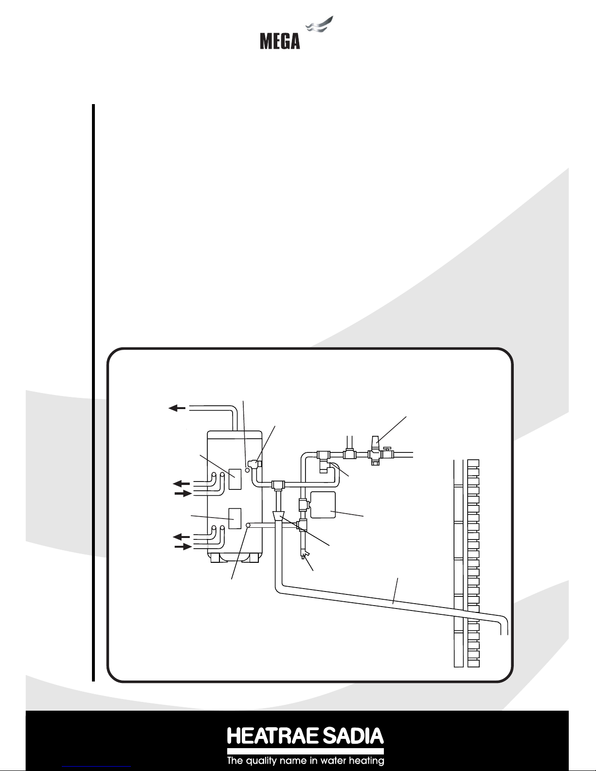
Diagram 1 - Schematic installation details
COLD WATER
COMBINATION
VALVE
BALANCED
COLD WATER
CONNECTION
(IF REQUIRED)
T&P RELIEF
VALVE
AUXILIARY
CONTROLS
HOUSING
AUXILIARY
PRIMARY RETURN
SOLAR PRIMARY
FLOW
INLET
DRAIN COCK DISCHARGE
PIPE
TUNDISH
SECONDARY RETURN
TAPPING (IF REQUIRED)
TO HOT
OUTLETS
MAINS
WATER
SUPPLY
EXPANSION VALVE
CORE UNIT (SEE
NOTE BELOW)
NOTE: FOR BALANCED PRESSURE COLD WATER SUPPLIES TEE OFF BETWEEN THE COLD
WATER COMBINATION VALVE AND THE EXPANSION VALVE CORE UNIT.
SOLAR PRIMARY
RETURN
AUXILIARY
PRIMARY FLOW
SOLAR CONTROLS
HOUSING EXPANSION
VESSEL

4
4
techtech
IMPORTANT : PLEASE READ AND UNDERSTAND THESE INSTRUCTIONS BEFORE INSTALLING
THE MEGATECH WATER HEATER. INCORRECT INSTALLATION MAY INVALIDATE GUARANTEE.
THIS APPLIANCE IS NOT INTENDED FOR USE BY PERSONS (INCLUDING CHILDREN) WITH
REDUCED PHYSICAL, SENSORY OR MENTAL CAPABILITIES, OR LACK OF KNOWLEDGE AND
EXPERIENCE, UNLESS THEY HAVE BEEN GIVEN SUPERVISION OR INSTRUCTION CONCERNING
THE USE OF THE APPLIANCE BY A PERSON RESPONSIBLE FOR THEIR SAFETY.
THE MEGATECH SOLAR MUST BE INSTALLED (SECTIONS 2 - 6), COMMISSIONED (SECTION 7)
AND MAINTAINED (SECTIONS 9 - 10) BY A COMPETENT INSTALLER IN ACCORDANCE WITH
BUILDING REGULATION G3 (ENGLAND AND WALES), TECHNICAL STANDARD P3 (SCOTLAND)
OR BUILDING REGULATION P5 (NORTHERN IRELAND) AND THE WATER FITTING REGULATIONS
(ENGLAND AND WALES) OR WATER BYELAWS (SCOTLAND). FOLLOWING INSTALLATION AND
COMMISSIONING, THE OPERATION OF THE HEATER SHOULD BE EXPLAINED TO THE USER
(SECTION 8) AND THESE INSTRUCTIONS LEFT WITH THEM FOR FUTURE REFERENCE.
2.1 COMPONENT CHECK LIST
Before commencing installation check that all the components for your Megatech Solar unit are
contained in the package. The following components are supplied as standard with your Megatech
unit :
•Factory fitted immersion heater (s) and thermal controls
•Cold Water Combination Valve (comprises Isolating Valve, Pressure Reducing Valve,
Strainer, and Check Valve).
•Expansion Core Unit (comprises Check Valve and Expansion Valve)
•Expansion Vessel (including wall mounting bracket)
•Factory fitted Temperature/Pressure Relief Valve (set at 90oC/10bar)
•T&P Relief Valve Insulation Set
•Drain Valve
•Wiring Centre (CL units only)
•Tundish (included in the Cold Water Combination Valve pack)
•Factory fitted Auxiliary heating coil Thermostat and Thermal Cut-out (CL units only)
•2-port Motorised Valve (CL units only)
•Lifting handle
2.2 SITING THE MEGATECH SOLAR (see Diagram 1)
The Megatech Solar unit must be vertically floor mounted. It can be placed anywhere convenient
provided the discharge pipe(s) from its safety valves can be correctly installed. Areas that are
subject to freezing must be avoided. Ensure that the floor is of sufficient strength to support the “full”
weight of the unit (refer to Tables 4 and 5 on page 33 for unit weights). Pipe runs should be kept as
short as possible for maximum economy. Access to associated controls, immersion heaters and
controls housings should be possible for servicing and maintenance of the system (Note: controls
housings hinge open to the left hand side).
Please do not install valves or pipework (except discharge pipe) within 50mm (2”) of the T&P relief
valve to allow your insulation set to be fitted. The insulation set is important to ensure heat and
energy conservation. See section 3.9 for more information.
To aid installation the Megatech Solar is provided with lifting points located in the base moulding and
a lifting handle. The lifting handle should be fully threaded onto the outlet boss before use. Once the
Megatech Solar is suitably positioned the lifting handle should be removed to allow connection of the
outlet pipework. The weights of the units are noted on the tables on page 33.
2General Requirements
General Requirements

5
tech
2.3 WATER SUPPLY
Bear in mind that the mains water supply to the property will be supplying both the hot and cold
water requirements simultaneously. It is recommended that the maximum water demand
be assessed and the water supply checked to ensure this demand can be met.
NOTE: A high mains water pressure will not always guarantee high flow rates.
Wherever possible the main supply pipe should be in 22mm. We suggest that the minimum
supply requirements should be 0.15 MPa (1.5 bar) working pressure and 20 litres per minute
flowrate. At these values outlet flowrates may be poor if several outlets are used simulta-
neously, the higher the available pressure and flowrate the better the system performance will
be.
The Megatech Solar has an operating pressure of 0.3 MPa (3 bar) which is controlled by the
Cold Water Combination Valve. The Cold Water Combination Valve can be connected to a
maximum mains supply pressure of 1.6 MPa (16 bar). The water supply must be of
wholesome water quality (Fluid Category 1 as defined by the Water Supply Regulations 1999).
2.4 OUTLET/TERMINAL FITTINGS (TAPS, ETC.)
The Megatech Solar can be used in conjunction with most types of terminal fittings. It is
advantageous in many mixer showers to have balanced hot and cold water supplies. In these
instances the balanced cold water supply should be teed off the supply to the Megatech
immediately after the Cold Water Combination Valve (see Diagrams 4 and 5). Branches to cold
drinking outlets should be taken before the valve.
Outlets situated higher than the Megatech Solar unit will give outlet pressures lower than that at
the heater, a 10m height difference will result in a 0.1 MPa (1 bar) pressure reduction at the
outlet fitting.
NOTE: Accessories should have a rated operating pressure of at least 0.8 MPa (8 bar).
2.5 LIMITATIONS
The Megatech Solar unvented water heater should not be used in any of the following
instances:
• Solid fuel boilers or any other boiler in which the energy input is not under effective
thermostatic control unless additional and appropriate safety measures are installed.
• Gravity circulation primaries.
• Steam heating plant unless additional and appropriate safety devices are installed.
• Ascending spray type bidets or any other Class 5 back syphonage risk requiring that a
Type AA, AB, AD or AG air gap be employed.
• Water supplies that have inadequate pressure or where the supply may be intermittent.
• Situations where it is not possible to safely pipe away any discharge from the safety
valves.
• Areas where the water consistently contains a high proportion of solids, eg. suspended
matter that could block the strainer, unless adequate filtration can be ensured.
• The installation must be carried out in accordance with the relevant requirements of:
• The appropriate Building Regulations: either The Building Regulations (England), The
Building Regulations (Scotland) or Building Regulations (Northern Ireland).
• The Water Fittings Regulations (England and Wales) or Water Byelaws (Scotland).

6
6
techtech
3
3.1 PIPE FITTINGS
All pipe connections to the Megatech Solar are made via 22mm compression fittings directly to the
unit (nuts and olives supplied). The fittings are also threaded 3/4” BSP male parallel should threaded
pipe connections be required.
3.2 COLD WATER SUPPLY
A 22mm cold water supply is recommended, however, if a 15mm (1/2”) supply exists which
provides sufficient flow (see section 2.3) this may be used. More flow noise may be experienced
from small bore pipes due to the increased water velocity through them.
The Cold Water Combination Valve supplied with the Megatech Solar incorporates a full flow
isolating valve which will enable the Megatech to be isolated from the mains supply for maintenance
or servicing. To close the valve the black handle should be turned so that it lies at 90oto the direction
of flow. To open turn the handle so that it lies parallel to the direction of flow.
3.3 COLD WATER COMBINATION VALVE (see Diagram 2)
The Cold Water Combination Valve can be connected anywhere on the cold water mains supply
prior to the Megatech Solar unit. There is no requirement to site it close to the unit, it can be located
at a point where the mains supply enters the premises if this is more convenient. The Expansion
Valve connection must not be used for any other purpose.
The Cold Water Combination Valve can be installed as a complete one-piece unit. The valve
incorporates a factory set, non-adjustable Pressure Reducer/Strainer, an Expansion Valve
connection and a single Check Valve. The valve can be fitted in any orientation to suit the
installation, however, ensure that the Valve is installed with the direction of flow arrows (stamped on
the side of the brass body) pointing towards the Megatech heater. Should you wish to site the
Expansion Valve on the Cold Water Combination Valve this can be done by unscrewing the
connection nut beneath the Expansion Valve on the Expansion Core Unit and removing the
Expansion Valve. The connecting nut and blanking plug should then be unscrewed from the Cold
Water Combination Valve and replaced with the Expansion Valve. NOTE: IF THE EXPANSION
VALVE IS FITTED TO THE COLD WATER COMBINATION VALVE THE EXPANSION CORE
UNIT SHOULD NOT BE USED AS THE CHECK VALVE WITHIN IT WILL PREVENT FREE
PASSAGE OF EXPANDED WATER TO THE EXPANSION VALVE. Ensure the discharge from
the Expansion Valve can be correctly installed.
If a balanced pressure cold water supply is required to a thermostatic shower mixer valve this may
be teed off the supply to the Megatech immediately after the Cold Water Combination Valve (see
Diagram 5). Branches to drinking water outlets should be taken before the valve to avoid
the possibility of warm expanded water being drawn from the tap.
3.4 EXPANSION CORE UNIT (see Diagram 3)
Should a balanced pressure cold water supply be required for other cold water outlets the
Expansion Core Unit supplied should be used. The Core Unit should be fitted into the pipework
Installation - General
Installation - General

7
tech
between the Cold Water Combination Valve and the Megatech Solar (Note direction of flow
arrows). The cold water balanced draw off connection should be taken from between the Cold
Water Combination Valve and the Expansion Core Unit (see Diagram 4). The Expansion
Valve connection on the Cold Water Combination Valve should remain blanked off using the
blanking nut and seal provided. Ensure the discharge from the Expansion Valve can be
correctly installed.
Diagram 2 - Cold Water Combination Valve
Diagram 3 - Expansion Core Unit
ISOLATING VALVE
MAINS IN
22MM
COMPRESSION
CONNECTION
PRESSURE REDUCING
VALVE HOUSING
PRESSURE REDUCING
VALVE CARTRIDGE
(3 BAR)
22MM
COMPRESSION
CONNECTION
OUTLET TO
MEGAFLO
EXPANSION VALVE
CONNECTION (IF
ONE-PIECE VALVE
IS REQUIRED)
TAKE NOTE OF
FLOW DIRECTION
EXPANSION RELIEF VALVE
DISCHARGE CONNECTION
EXPANSION RELIEF VALVE
FROM COLD
WATER
COMBINATION
VALVE
OUTLET TO
MEGAFLO
22MM COMPRESSION
CONNECTION
EXPANSION CORE UNIT
(INCORPORATES
CHECK VALVE)
MOUNTING NUT 22MM COMPRESSION
CONNECTION
TAKE NOTE OF
FLOW DIRECTION
8
8
techtech
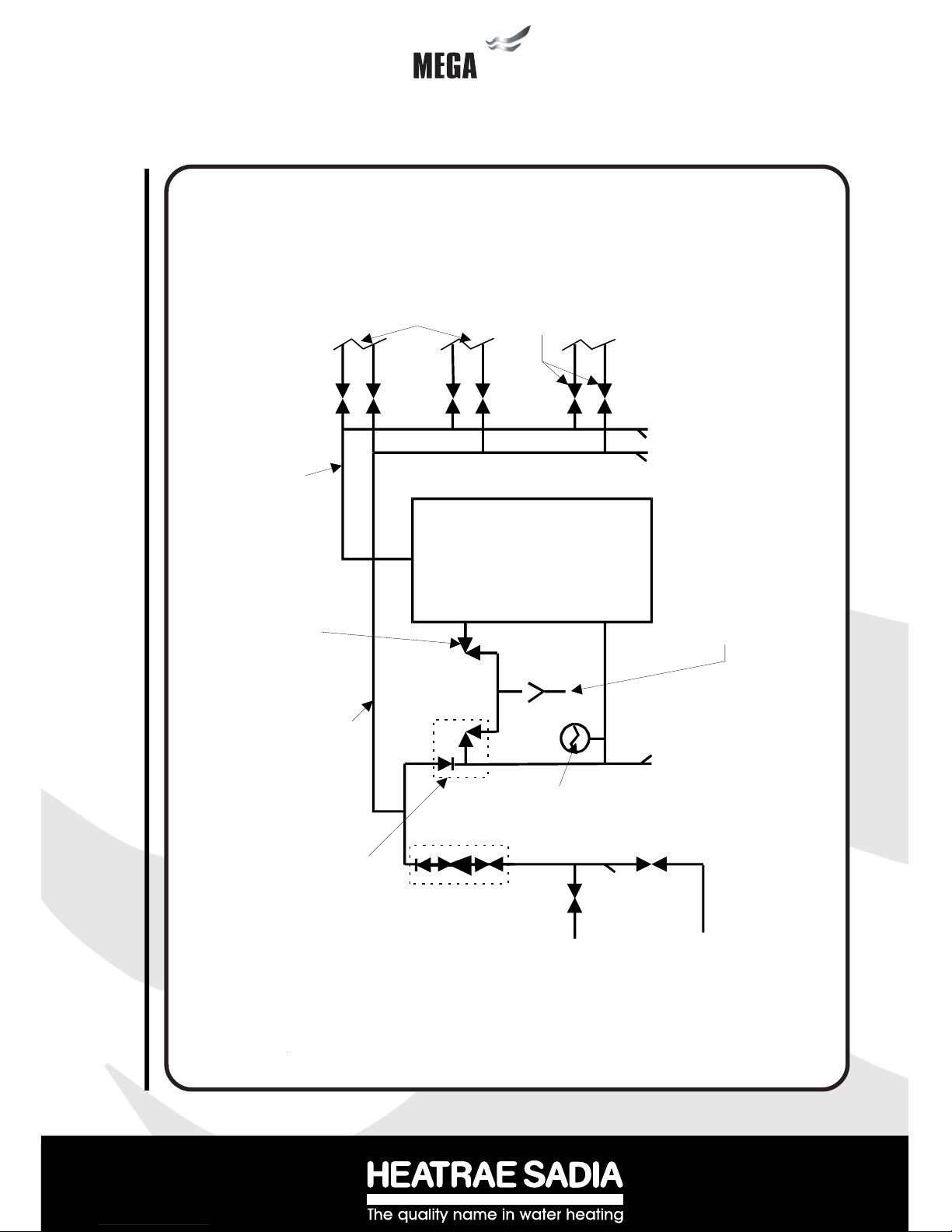
Tundish
Megatech
Solar
Discharge pipe to atmosphere
(See Section 3.9 “Discharge
Pipework“)
KEY
MCWS Mains cold water supply
HWS Hot water service
SC Stop Cock
DOC Drain Off Cock
Temperature/Pressure
Relief Valve
Balanced cold water
draw off
Balanced HWS and
MCWS to bathrooms,
showers,cloakrooms,
etc.
Isolating/Regulating
Valves as required
HWS supply
Expansion Core
Unit (combined
Expansion Relief
Valve/Check Valve)
SC
SC
DOC
EXPANSION
VESSEL
Incoming Cold
Water Main
MCWS to Kitchen
(unbalanced cold
mains supply)
Cold Water Combination
Valve incorporating
Pressure Reducing Valve,
Isolating Valve, Strainer
and Check Valve
NB Expansion Valve
tapping must be blanked
off
DOC DOC DOC
Diagram 4 - Schematic installation diagram using Cold Water Combination Valve in
conjunction with Expansion Core Unit
Installation - General
9
tech
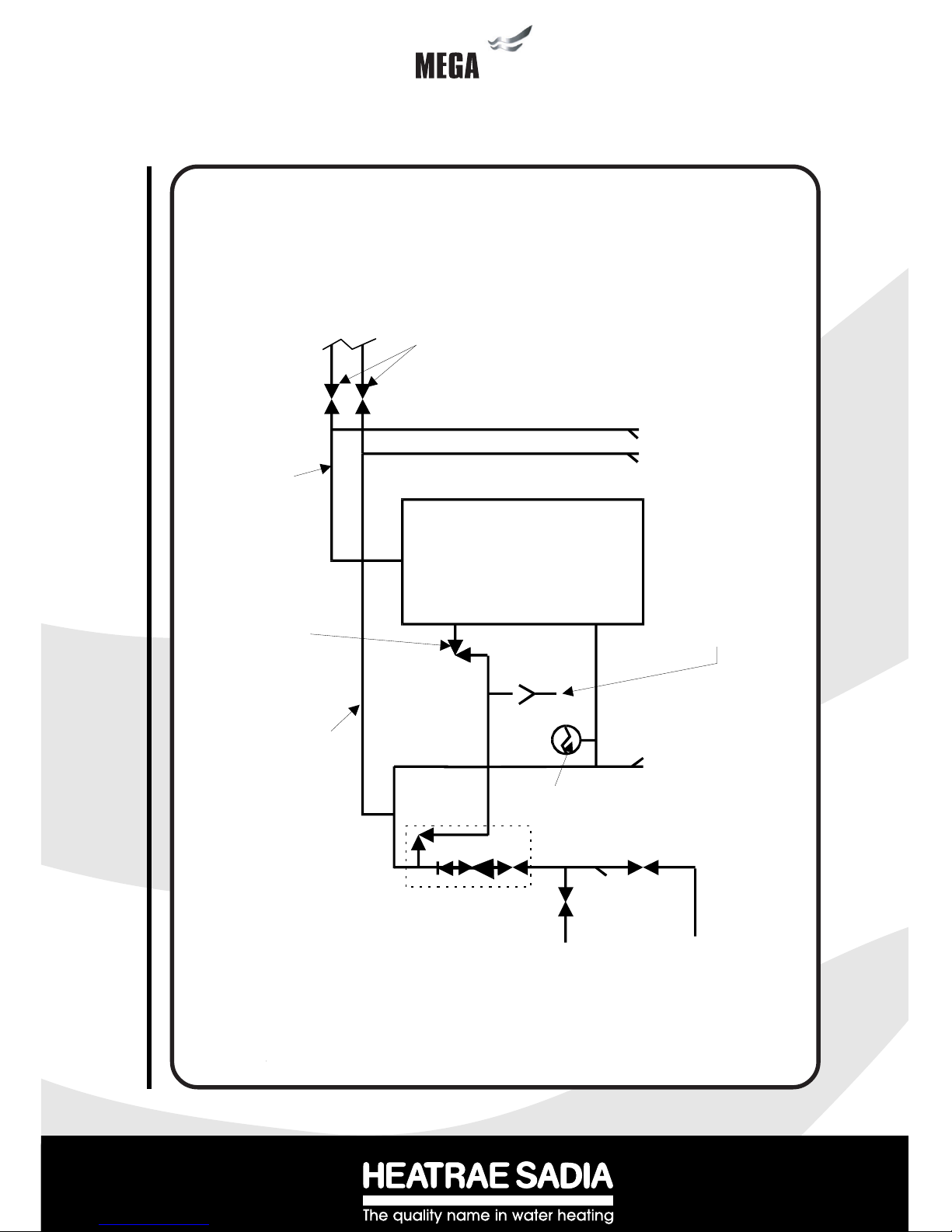
Diagram 5 - Schematic installation diagram using Cold Water Combination Valve
Tundish
Megatech
Solar
Discharge pipe to atmosphere
(See Section 3.8 “Discharge
Pipework“)
KEY
MCWS Mains cold water supply
HWS Hot water service
SC Stop Cock
DOC Drain Off Cock
Temperature/Pressure
Relief Valve
Balanced cold water
draw off to shower
mixer valves (Note:
tapping must be min.
3m from Megaflo
inlet connection)
Balanced HWS and
MCWS to each
shower.
Isolating/Regulating
Valves as required
HWS supply
SC
SC
DOC
Incoming Cold
Water Main
Incoming Cold
Water Main
MCWS to Kitchen
and drinking water
outlets (unbalanced
cold mains supply)
Cold Water Combination
Valve incorporating
Pressure Reducing Valve,
Isolating Valve, Strainer
and Check Valve and
Expansion Relief Valve
DOC DOC DOC
EXPANSION
VESSEL

10
10
techtech
3.5 DRAIN TAP
A draining tap is supplied and should be installed in the cold water supply to the Megatech Solar unit
between the Cold Water Combination Valve (or Expansion Core Unit if being used) and the heater
at as low a level as possible (see Diagram 1). It is recommended that the outlet point of the drain
pipe work be at least 1 metre below the level of the heater (this can be achieved by attaching a hose
pipe to the drain tap outlet spigot). The drain tap supplied provides very good water flow control and
blanking cap for extra security.
3.6 OUTLET PIPEWORK
Ideally the pipework from the Megatech Solar to the outlet fittings should be in 22mm pipe with short
runs of 15mm pipe to showers and basin taps. Small bore pipe can also be used to suit some taps,
but runs should be of minimum length. Pipe sizes may vary due to system design.
3.7 EXPANSION VESSEL
The Expansion Vessel accommodates expansion that results from heating the water inside the unit. The
unit is pre-charged at 0.35 MPa (3.5 bar). The Expansion Vessel must be connected between the Cold
Water Combination Valve and the Megatech Solar (see Diagram 1). The location of the Expansion
Vessel should allow access to recharge the pressure as and when necessary, this can be done using
a normal car foot pump. It is recommended that the Expansion Vessel is adequately supported. An
Expansion Vessel wall mounting bracket is supplied for this purpose.
NOTE: DO NOT USE THE POTABLE WATER EXPANSION VESSEL SUPPLIED WITH THE
MEGATECH SOLAR FOR ANY OTHER PURPOSE. IT MUST NOT BE USED IN PLACE OF
THE SOLAR PRIMARY SYSTEM EXPANSION VESSEL.
3.8 SECONDARY CIRCULATION
If a secondary circulation system is required it should be connected to the Megatech Solar as
shown in Diagram 6 via the connection provided. The secondary return pipe should be in 15mm
pipe and incorporate a check valve to prevent backflow.A suitable WRAS approved bronze
circulation pump will be required. On large systems, due to the increase in system water content, it
may be necessary to fit additional expansion volume to the system by fitting an external expansion
vessel to the secondary circuit. This should be done if the capacity of the secondary circuit exceeds
10 litres.
Pipe capacities (copper)
15mm o/d = 0.13 litres per metre run (10 litres = 77m)
22mm o/d = 0.38 litres per metre run (10 litres = 26m)
28mm o/d = 0.55 litres per metre run (10 litres = 18m)
Secondary circulation is NOT recommended for direct electric units being used on Off
Peak electricity tariffs. The secondary circulation return must not be connected to the inlet
as this would lead to indirect heating of the dedicated solar buffer volume.
Installation - General

11
tech
Diagram 6 - Secondary circulation connection
3.9 T&P RELIEF VALVE INSULATION
A set of insulating components is supplied with the Megaflo water heater and should be installed to
gain maximum heat and energy saving benefits. See Diagram 7 for installation instructions.
3.10 WARNINGS
i) Under no circumstances should the factory fitted Temperature/Pressure Relief Valve
be removed other than by Authorised Heatrae Sadia personnel. To do so will
invalidate any guarantee or claim.
ii) The Cold Water Combination Valve must be fitted to the mains
water supply to the Megatech unit.
iii) No control or safety valves should be tampered with.
iv) Water may drip from the discharge pipe of the pressure relief device (Expansion
Valve) and this pipe must be left open to atmosphere. The discharge pipe should not
be blocked or used for any other purpose.
SECONDARY RETURN
CONNECTION
CHECK VALVE
SECONDARY
CIRCULATION PUMP
OUTLET
SECONDARY
RETURN
T&P RELIEF
VALV E
DISCHARGE
PIPEWORK
TO TUNDISH
'FEMALE'
INSULATING
PIECE
'MALE'
INSULATING
PIECE
DISCHARGE
PIPE
PLASTIC
COVER
CLIP
INTO
PLACE!
AB
CD
Diagram 7 - Installation of T&P Insulating set
12
12
techtech
3.11 DISCHARGE PIPEWORK
It is a requirement of Building Regulations that any discharge from an unvented system is conveyed to
where it is visible, but will not cause danger to persons in or about the building. The tundish and discharge
pipes should be fitted in accordance with the requirements and guidance notes of Building Regulations.
Building Regulation G3 Requirements and Guidance section 3.9 are reproduced in the following sec-
tions.
Information Sheet No. 33 available from the British Board of Agrément gives further advice on discharge
pipe installation. For discharge pipe arrangements not covered by G3 Guidance or BBA Info Sheet
No.33 advice should be sought from your local Building Control Officer.
Any discharge pipe connected to the pressure relief devices (Expansion Valve and Temperature/
Pressure Relief Valve) must be installed in a continuously downward direction and in a frost free
environment.
G3 REQUIREMENT
“...there shall be precautions...to ensure that the hot water discharged from safety devices is safely
conveyed to where it is visible but will not cause danger to persons in or about the building.”
G3 GUIDANCE SECTION 3.9
The discharge pipe (D1) from the vessel up to and including the tundish is generally supplied by the
manufacturer of the hot water storage system. Where otherwise, the installation should include the
discharge pipe(s) (D1) from the safety device(s). In either case the tundish should be vertical, located in
the same space as the unvented hot water storage system and be fitted as close as possible and within
500mm of the safety device e.g. the temperature relief valve.
The discharge pipe (D2) from the tundish should terminate in a safe place where there is no risk to
persons in the vicinity of the discharge, preferably be of metal and:
a. be at least one pipe size larger than the nominal outlet size of the safety device unless its total
equivalent hydraulic resistance exceeds that of a straight pipe 9m long i.e. discharge pipes between 9m
and 18m equivalent resistance length should be at least two sizes larger than the nominal outlet size of
the safety device, between 18 and 27m at least 3 sizes larger , and so on. Bends must be taken into
account in calculating the flow resistance. Refer to Diagram 7, Table 1 and the worked example.
An alternative approach for sizing discharge pipes would be to follow BS 6700:1987 Specification for
design, installation, testing and maintenance of services supplying water for domestic use within
buildings and their curtilages, Appendix E, section E2 and table 21.
b. have a vertical section of pipe at least 300mm long below the tundish before any elbows or bends in
the pipework.
c. be installed with a continuous fall.
d. have discharges visible at both the tundish and the final point of discharge, but where this is not
possible or is practically difficult there should be clear visibility at one or other of these locations.
Installation - General
13
tech
Examples of acceptable discharge arrangements are:
i. ideally below a fixed grating and above the water seal in a trapped gully.
ii. downward discharges at low level; i.e. up to 100mm above external surfaces such as car
parks, hard standings, grassed areas etc. are acceptable providing that where children may play
or otherwise come into contact with discharges a wire cage or similar guard is positioned to prevent
contact, whilst maintaining visibility.
iii. discharges at high level; e.g. into a metal hopper and metal down pipe with the end of the
discharge pipe clearly visible (tundish visible or not) or onto a roof capable of withstanding high
temperature discharges of water and 3m from any plastics guttering system that would collect such
discharges (tundish visible).
iv. where a single pipe serves a number of discharges, such as in blocks of flats, the number
served should be limited to not more than 6 systems so that any instalation discharging can be
traced reasonably easily. The single common discharge pipe should be at least one pipe size larger
than the largest individual discharge pipe (D2) to be connected. If unvented hot water storage
systems are installed where discharges from safety devices may not be apparent i.e. in dwellings
occupied by blind, infirm or disabled people, consideration should be given to the installation of an
electronically operated device to warn when discharge takes place.
Note: The discharge will consist of scalding water and steam. Asphalt, roofing felt and non-metallic
rainwater goods may be damaged by such discharges.
Worked example of discharge pipe sizing
The example below is for a G1/2 temperature relief valve with a discharge pipe (D2) having 4
No. elbows and length of 7m from the tundish to the point of discharge.
From Table 1:
Maximum resistance allowed for a straight length of 22mm copper discharge pipe (D2) from a
G1/2 temperature relief valve is 9.0m.
Subtract the resistance for 4 No. 22mm elbows at 0.8m each = 3.2m
Therefore the permitted length equates to: 5.8m
5.8m is less than the actual length of 7m therefore calculate the next largest size.
Maximum resistance allowed for a straight length of 28mm pipe (D2) from a G1/2 temperature
relief valve equates to 18m.
Subtract the resistance of 4 No. 28mm elbows at 1.0m each = 4.0m
Therefore the maximum permitted length equates to: 14m
As the actual length is 7m, a 28mm (D2) copper pipe will be satisfactory.

14
14
techtech
Installation - General
Valve outlet size Minimum size of
discharge pipe
D1
Minimum size of
discharge pipe
D2 from tundish
Maximum
re sista n ce
allowed,
expressed as a
length of straight
pipe (i.e. no
elbows or bends)
Re si sta n ce
created by each
elbow or bend
G1/2 15mm
22mm
28mm
35mm
up to 9m
up to 18m
up to 27m
0.8m
1.0m
1.4m
G3/4 22mm
28mm
35mm
42mm
up to 9m
up to 18m
up to 27m
1.0m
1.4m
1.7m
G1 28mm
35mm
42mm
54mm
up to 9m
up to 18m
up to 27m
1.4m
1.7m
2.3m
Fixed grating
Discharge below
fixed grating
(Building Regulation
G3 section 3.9d gives
alternative points
of discharge)
Trapped
gully
Discharge pipe (D2) from tundish,
with continuous fall. See Building
Regulation G3 section 3.9d i-iv,
Table 4 and worked example
300mm
minimum
500mm maximum
Metal discharge pipe (D1) from
Temperature relief valve to tundish
Tundish
Safety device
(e.g. Temperature
relief valve)
Table 1 - Sizing of copper discharge pipe (D2) for common T&P relief valve sizes
Diagram 8 - Schematic discharge pipe arrangement
15
tech
4
Installation - Solar Primary
Installation - Solar Primary
4.1 CONNECTION TO SOLAR PRIMARY CIRCUIT
The lower (solar) coil of the Megatech Solar must be connected to a fully pumped solar primary
circuit. The connections (see diagram 17) are suitable for 22mm copper pipe direct to the compres-
sion fittings provided. The connections are also threaded 3/4” BSP male parallel should BSP
connections be required.
The solar primary circuit must have its own dedicated circulating pump, thermal and safety controls
which must be installed as per the manufacturer’s instructions.
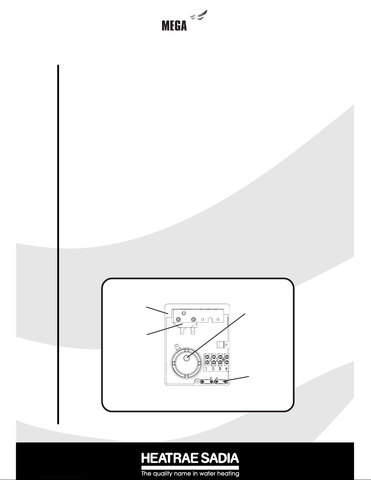
4.2 CONTROL OF SOLAR PRIMARY CIRCUIT
Temperature control of the Megatech Solar must be carried out using a suitable proprietary solar
differential temperature controller. The cylinder temperature sensing probe (usually supplied with the
solar differential temperature controller) should be inserted into the pocket provided on the Megatech
Solar (see diagram 9) and its cable secured using the cable clamp supplied.
The solar controller and solar primary circulation pump must be wired via the over-temperature cut-
out mounted in the lower solar controls housing (see diagram 9). This will ensure that the heat input
to the solar coil is interrupted in the event of the cylinder over-heating. There must also be suitable
Check (non-return) valves installed in the solar primary flow and return to prevent the possibility of
any thermo-syphoning if the solar circulation is stopped.
Connection to the solar differential temperature controller should be in accordance with the
manufacturer’s instructions. The controller should be set to give a recommended cylinder tempera-
ture of approx. 60oC. The maximum setting should not exceed 70oC otherwise nuisance operation of
the thermal cut-outs may occur.
Diagram 9 - Solar Coil Control Connections
Cylinder Temperature
Control Probe Pocket
Cable Clamp
Solar Cylinder
Controls Housing
Over Temperature
cut out
Note: wires removed from diagram for clarity

16
16
techtech
Installation - Direct units
5.1 IMMERSION HEATER(S)
The Megatech Solar Direct is supplied with two factory fitted immersion heaters. Each immersion
heater is rated 3kW at 240V.
To remove the immersion heater:
Ensure the cylinder is drained of water first. Open the cover to the upper immersion heater. Unplug
the thermostat from the element by gently pulling the thermostat outwards. Unscrew the brass
backnut using the key spanner provided. Remove the immersion heater assembly and sealing
gasket from the boss.
Replacement:
Insert the immersion heater and sealing gasket into the required boss. Ensure that the sealing gasket
is not displaced when inserting. It may be helpful to support the immersion heater using a round
bladed screwdriver inserted into one of the thermostat pockets. Hand tighten the brass backnut.
Secure the immersion heater in position by tightening with the key spanner provided. Insert the
blanking plate into the remaining boss ensuring the sealing gasket is not displaced when inserting.
Hand tighten the brass backnut. Secure in position by tightening with the key spanner provided.
If an additional immersion heater is required order Part No. 95 970 510.
5.2 WIRING (see Diagram 10)
All electrical wiring should be carried out by a competent electrician and be in accordance with the
latest I.E.E. Wiring Regulations. Each circuit must be protected by a suitable fuse and double
pole isolating switch with a contact separation of at least 3mm in both poles.
The immersion heater(s) should be wired in accordance with Diagram 10. The immersion heaters
MUST be earthed. The supply cable should be 1.5mm23 core HOFR sheathed and must be routed
through the cable gland provided with the outer sheath of the cable firmly secured by tightening the
screw on the cable gland. Replace the immersion heater cover(s) before operating ensuring that the
threaded edge clip is in position to provide a suitable thread for the cover screw.
DO NOT OPERATE THE IMMERSION HEATER(S) UNTIL THE MEGATECH SOLAR HAS
BEEN FILLED WITH WATER..
5.3 OPERATION
It is recommended that the immersion heater thermostats are set to between position 4 and 5 (60o-
65oC), however they can be set between 1 and 5 (10o and 70oC). The thermostat incorporates a
thermal cut-out that will switch off the immersion heater in the event of a thermostat failure. The
thermal cut-out reset button position is indicated on Diagram 10. DO NOT bypass the thermal cut-out
in any circumstances.
5Installation - Direct units

17
tech
5.4 SAFETY
DO NOT BYPASS THE THERMAL CUT-OUT(S) IN ANY CIRCUMSTANCES.
DISCONNECT FROM THE MAINS SUPPLY BEFORE REMOVING ANY COVERS.
NEVER ATTEMPT TO REPLACE AN IMMERSION HEATER OTHER THAN WITH THE
RECOMMENDED HEATRAE SADIA MEGATECH SOLAR SPARE PART.
Diagram 10 -
Schematic wiring
diagram - Direct
immersion
heaters
THERMOSTAT
FUSED (13A) DOUBLE
POLE ISOLATING
SWITCH
Diagram 11 - Immersion heater details
1.5mm23 CORE
HOFR SHEATHED
CABLE
BROWN
BLUE
GREEN/YELLOW
THERMAL CUT-OUT
RESET BUTTON
ELECTRICAL
TERMINATIONS
CUSTOMER
EARTHING
TERMINAL
CABLE GLAND
NOTE: FOR CLARITY THE EARTH LINK WIRE BETWEEN CUSTOMER EARTHING
TERMINAL AND EARTHING TAG NOT SHOWN.THIS MUST NOT BE REMOVED!
EARTHING TAG
THERMOSTAT
ADJUSTMENT
THERMOSTAT
THREADED EDGE CLIP
EARTH
CONNECTION

18
18
techtech
Installation - Auxiliary coil
6.1 BOILER SELECTION
The Megatech Solar Indirect (CL) models are supplied with an auxiliary heating coil suitable for use
with most gas or oil fired boilers compatible with unvented systems i.e. fitted with a temperature
control thermostat and thermal cut-out.
If in doubt consult the boiler manufacturer.
Solid fuel boilers or any other boiler in which the energy input is not under effective thermostatic
control unless additional and appropriate safety measures are installed should NOT be used.
The boiler used can either be a sealed system or open vented type, maximum primary circuit
pressure 0.3 MPa (3 bar).
The primary flow from the boiler MUST be pumped. Gravity circulation will not work due to the
special design of the primary heat exchanger. It is recommended that an air bleed point or automatic
air vent is incorporated in the primary return pipework close to the Megatech Solar unit.
The boiler flow temperature should usually be set to 82oC (maximum flow temperature to primary
heat exchanger 90oC).
The boiler cannot be vented through the Megatech Solar unit.
6.2 INDIRECT THERMAL CUT-OUT AND 2-PORT MOTORISED VALVE
To comply with Building Regulations and to prevent the Megatech Solar from overheating the 2-port
motorised valve supplied MUST be fitted to the primary flow to the auxiliary heating coil (see
Diagram 12).
6.3 WIRING
All electrical wiring should be carried out by a competent electrician and be in accordance with the
latest I.E.E. Wiring Regulations.
The Megatech Solar Indirect Thermostat and Thermal Cut-out are factory pre-wired. The 2-port
motorised valve supplied MUST be wired in series with the Indirect controls such that the power
supply to the valve is interrupted should either the Thermostat or Thermal Cut-out operate. The Wiring
Diagrams 14 or 15 detail the wiring required between these controls and the motorised valve. Wiring
to external controls is made via the terminal block fitted. The cable should be routed through the
aperture in the terminal cover and secured using the cable clamp provided. The Indirect Thermal
Cut-out MUST NOT be bypassed.
6.4 HEATING SYSTEM CONTROLS
The controls provided with the Megatech Solar will ensure the safe operation of the Megatech Solar
within a central heating system. Other controls will be necessary to control the space heating
requirements and times that the system is required to function. Depending on the boiler selected,
heating circuit design and controls used it may be beneficial to incorporate a system bypass in the
heating system pipework.
6Installation - Auxiliary coil
(Indirect units)

19
tech
The Megatech Solar is compatible with most heating controls, examples of electrical circuits are
given in Diagrams 14 and 15. However, other systems may be suitable, refer to the
controls manufacturer’s instructions, supplied with the controls selected, for
alternative system wiring schemes.
5.5 IMMERSION HEATER
The Megatech Solar indirect units (CL models) are supplied with an immersion heater which
can be used as an alternative heat source should the boiler supply need to be isolated from the
Megatech unit. The immersion heater is located within the controls housing. Refer to Sections
4.2 and 4.3 and Diagram 10 for details of wiring and operation of the immersion heater.
Diagram 12 - Primary connections to indirect (CL) units
TO HOT
OUTLETS
PRIMARY
RETURN
PRIMARY
FLOW
AIR
VENT
2 PORT MOTORISED
VALVE (SUPPLIED) INLET
AUXILLARY
HEAT SOURCE
PRIMARY
RETURN
PRIMARY
FLOW
SOLAR
PRIMARY
CIRCUIT

20
20
techtech
CABLE CLAMPS TERMINAL BLOCK
INDIRECT
THERMOSTAT
THERMOSTAT
ADJUSTMENT
INDIRECT
THERMAL
CUT-OUT
INDIRECT THERMAL
CUT-OUT RESET
BUTTON
NOTE:
THE HOUSING COVER AND ELEMENT ASSEMBLY HAVE BEEN REMOVED
FROM THIS VIEW FOR CLARITY
Diagram 13 - Indirect controls housing details
Installation - Indirect units
Table of contents
Popular Water Heater manuals by other brands

Raypak
Raypak WH 0135A Installation & operating instructions

Quietside
Quietside DPW-199C user manual

A.O. Smith
A.O. Smith GPS-75 instruction manual

Strom-Electrical
Strom-Electrical SEUS6L installation manual

PVI Industries
PVI Industries QuickDraw Installation & maintenance manual

Spheros
Spheros Thermo S 230 Workshop manual

State Water Heaters
State Water Heaters 184671-000 instruction manual

Main
Main MULTIPOINT FF User operating, installation and servicing instructions

Bradford White
Bradford White Copper Brute II BWCH 2000 Installation and operating instructions

Takagi
Takagi T-K1 Installation manual and owner's guide

PVI Industries
PVI Industries COBREX Installation & maintenance manual

Aspes
Aspes ATE51D user manual


