Meilhaus Electronic ME-5004 User manual

Meilhaus Electronic Manual
ME-5004 1.2E
Plug-on Board for ME-5000 Series
with opto-isolated Digital I/Os
(alternative configuration: Frequency Measurement and Pulse Generator)

Imprint
ME-5810 Manual
Version 1.2E
Issued on: 17. Oktober 2013
Meilhaus Electronic GmbH
Fischerstraße 2
D-82178 Puchheim/Munich
Germany
http://www.meilhaus.com
© Copyright 2013 Meilhaus Electronic GmbH
All rights reserved. No part of this publication may be reproduced or distributed in any
form whether photocopied, printed, put on microfilm or be stored in any electronic media
without the expressed written consent of Meilhaus Electronic GmbH.
Important note:
The information contained in this manual has been reviewed with great care and is believed
to be complete and accurate. Meilhaus Electronic assumes no responsibility for its use, any
infringements of patents or other rights of third parties which may result from use of this
manual or the product. Meilhaus Electronic assumes no responsibility for any problems or
damage which may result from errors or omissions. Specifications and instructions are
subject to change without notice.
Borland Delphi is a trademark of Borland International Inc.
Turbo/Borland C is a trademark of Borland International Inc.
Visual C++ and Visual Basic are trademarks of the Microsoft Corporation.
VEE Pro and VEE OneLab are trademarks of Agilent Technologies.
ME-VEC and ME-FoXX are trademarks of Meilhaus Electronic.
Other company names and product names found in the text of this manual are also
trademarks of the companies involved.

Manual ME-5004 Rev. 1.2E
Meilhaus Electronic Seite 3 Table of Contents
Table of Contents
1Introduction......................................................................................................5
1.1 Important Notes ..................................................................................... 5
1.1.1 Intended Use ................................................................................ 5
1.1.2 Improper Use................................................................................ 6
1.1.3 Unforeseeable Misuse.................................................................... 6
1.2 Scope of Supply.......................................................................................7
1.3 Features ..................................................................................................8
1.4 System Requirements............................................................................10
1.5 Software Support .................................................................................. 10
2Initial Operation ............................................................................................. 11
2.1 Software Installation .............................................................................11
2.2 Test Program ........................................................................................11
2.3 Fitting the Plug-on Boards.................................................................... 12
3 Hardware ........................................................................................................15
3.1 Block Diagram ......................................................................................15
3.2 ME-5004 cPCI/PCIe .......................................................................... 16
3.3 Digital Input/Output ...........................................................................17
3.3.1 Opto-isolated Inputs ........................................................... 17
3.3.2 Opto-isolated Outputs .......................................................... 18
3.3.2.1 Sink Driver ................................................................. 18
3.3.2.2 Source Driver.............................................................. 20
3.3.3 External Trigger ........................................................................ 21
3.4 Frequency Input/Output ................................................................ 21
3.5 External Interrupt ..............................................................................22
4 Programming..................................................................................................23
4.1 Single Operation Mode......................................................................... 25
4.1.1 Digital Input/Output .......................................................... 25
4.1.2 Frequency Input/Output ....................................................... 26
4.1.2.1 Frequency Measurement ........................................ 27
4.1.2.2 Pulse Generator ....................................................... 28
4.2 Interrupt Operation ......................................................................... 29
4.2.1 Bit-pattern Change .................................................................. 29
4.2.2 Bit-pattern Compare .............................................................. 31

Rev. 1.2E Manual ME-5004
Table of Contents Seite 4 Meilhaus Electronic
Appendix ...............................................................................................................33
ASpecifications ........................................................................................33
BPinout ..................................................................................................39
B1 37-pin D-Sub (ST1).....................................................................40
CAccessories ............................................................................................41
DTechnical Questions..............................................................................42
D1 Hotline.........................................................................................42
D2 Service address..............................................................................42
D3 Driver Update ..............................................................................42
E Index.....................................................................................................43

Manual ME-5004 Rev. 1.2E
Meilhaus Electronic Seite 5 Introduction
1Introduction
Valued customer,
Thank you for purchasing this device from Meilhaus Electronic. You ha-
ve chosen an innovative high technology product that left our premises
in a fully functional and new condition.
Take the time to carefully examine the contents of the package for any
loss or damage that may have occurred during shipping. If there are any
items missing or if an item is damaged, contact us immediately.
Before you install the board in your computer, we recommend to read
this manual carefully, especially the chapter describing board installation.
1.1 Important Notes
1.1.1 Intended Use
The plug-on boards of the ME-5000 series require a base board of the
ME-5000 series and will be plugged onto these and extend the functio-
nality of the base boards. Depending on the PC platform the plug-on
board needs an additional:
• … free PCI Express slot (PCIe) or
• … free CompactPCI slot (cPCI),
however without using the PCI slot connector.
Please follow the instructions of chapter 2.3 on page 12 of this document
and the manual of your computer for the procedure when fitting additio-
nal hardware componets.
Observe the following notes and specifications starting on page 33:
• Make sure that heat can be dissipated from the board well enough
inside the PC housing.
• Unused inputs must always be connected to the reference ground of
their subdevice, in order to avoid crosstalk between the input
channels.

Rev. 1.2E Manual ME-5004
Introduction Seite 6 Meilhaus Electronic
• When using the configuration „pulse generator“ (FO) unused output
pins should not be connected.When using the sink driver the outputs
are in a high-impedance state, when using the source driver they are
connected to ground.
• The opto-isolated inputs and outputs provide electrical isolation bet-
ween device and application of up to 1000 V with respect to the PC
ground.
• Note that the computer must be switched on first before any voltage
is applied to the board through external circuitry.
• Connecting or disconnecting any of the the board's connectors must
always be done when all the components are powered down.
• Make sure that when touching the board, or when plugging in the
connecting cable, it is not possible for static discharges to pass
through the board.
• Ensure that the connecting cable is securely seated. The plug must be
fully inserted into the D-sub socket, and secured using both screws.
Only in this way can the board be expected to function properly.
1.1.2 Improper Use
Plug-on boards must never be operated outside the PC. Never connect
the devices to electrically live parts, and particularly not to any that carry
mains voltage.
Make sure that the external circuitry connected to the device cannot
come into contact with electrically live parts. Connecting or disconnec-
ting any of the the connectors must always be done when powered down.
1.1.3 Unforeseeable Misuse
The device is not suitable for use as a child's toy, for domestic purposes
or under adverse ambient conditions (such as in the open air). The user
must take appropriate precautions to avoid unforeseeable misuse.

Manual ME-5004 Rev. 1.2E
Meilhaus Electronic Seite 7 Introduction
1.2 Scope of Supply
We do, of course, endeavour to supply you a complete product package.
Nevertheless, to make entirely sure that your supply is complete, you can
check the contents of your package with the help of the following list.
Your package should contain the following parts:
• Opto-isolated digital-I/O board used as a plug-on board for the base
boards of the ME-5000 series
• Manual in PDF format on CD/DVD
• Driver software on CD/DVD
• 37-pin D-sub mating connector

Rev. 1.2E Manual ME-5004
Introduction Seite 8 Meilhaus Electronic
1.3 Features
The plug-on board of type ME-5004 is a opto-isolated digital-I/O boards
with bit-pattern detection for the base boards of the ME-5000 series. You
can configure individual subdevices alternatively for frequency measu-
rement resp. pulse generator on demand (see chapter 4from page 23).
Model overview:
* Alternative configuration can be selected with ME-iDC.
•Opto-isolated digital-inputs: The ME-5004 has 16 opto-isolated in-
puts (subdevice 0). The inputs run with a voltage high-level of 24 V
typ. (specifications see page 33).
•Opto-isolated digital-outputs: Die ME-5004 has 16 opto-isolated
outputs (subdevice 1). The source-driver can drive up to 500 mA per
pin. The detailed specifications of the sink and/or source drivers can
be found on page 34.
The source drivers are short-circuit-proof and are equipped with a
current limiting per channel. If required, the output driver can send
an interrupt on overload to the PC.
A suitable external source is required to supply the output drivers.
•Frequency counter: With the concept of “configurable subdevices”
the subdevice 0 can also be used as a frequency counter. Eight inde-
pendent channels are available to measure the frequency and duty
cycle of periodic rectangular signals (max. 300 kHz).
•Pulse generator: With the concept of “configurable subdevices” the
subdevice 1 can also be used as a rectangular signal generator. Eight
independent channels are available to output a periodic rectangular
signal up to 3 kHz with selectable duty cycle.
Model DIO FIO* Sink/
Source Bit-pattern
ME-5004
(Subdevice 0)
16 bit DI
(opto-isolated)
8 FI channels
(opto-isolated)
-- - Change
- Compare
(Subdevice 1) 16 bit DO
(opto-isolated)
8 FO channels
(opto-isolated)
4--
Ta b l e 1: Model overview ME-5810 series

Manual ME-5004 Rev. 1.2E
Meilhaus Electronic Seite 9 Introduction
•Sink/source selection: You can switch the output ports over from
sink to source drivers or high impedance by software for an optimal
adaption in industrial applications. “High impedance” means that
the voltage level at the output pin depends on your external applica-
tion.
•Bit-pattern detection: If required, the bit-pattern of an digital input
port can be monitored. Depending on the mode an interrupt can be
generated, if the bit-pattern changes or is equal/not equal to a given
bit-pattern.
• The isolation voltage between the opto-isolated inputs/outputs and
PC-ground is 1 kVACRMS.
• The opto-isolated digital inputs of the ME-5004 are equipped with
an overvoltage protection diode that can discharge voltage pulses to
ground for a short period of time.
For data transmission between PC memory and the base board the
ME-5004 must share the bandwidth with the base board. The actual
transmission rate depends on the operating mode and on the configura-
tion of your PC.
Depending on requirements, you can select from the following operation
modes:
•Single: In this operation mode, a single value can be read or written
under software control (see chapter 4.1 on page 25).
•Interrupt: For interrupt handling in the modes "bit-pattern change"
and "bit-pattern compare" (see chapter 4.2 on page 29).
Customer-specific versions of the firmware are available on request.

Rev. 1.2E Manual ME-5004
Introduction Seite 10 Meilhaus Electronic
1.4 System Requirements
The plug-on board requires a base board of the ME-5000 series and occu-
pies a free PCI Express or CompactPCI slot however without using the
PCI slot connector. This saves the resources of your PC. The board is
supported by the Meilhaus Intelligent Driver System (ME-iDS) from
Windows 2000 upwards (Linux under development).
1.5 Software Support
The plug-on boards of the ME-5000 series are supported by the
Meilhaus Intelligent Driver System (ME-iDS). The ME-iDS is an
unified driver system usable across devices and operating systems. It
supports Windows 8/7/Vista/XP/2000 (Linux under development) and
contains a universal function library (API) for programming.
You will find a detailed description of the functions in the ME-iDS ma-
nual, a copy of which is on the CD/DVD supplied.
Please also observe the notes in the appropriate README files.

Manual ME-5004 Rev. 1.2E
Meilhaus Electronic Seite 11 Initial Operation
2 Initial Operation
Please read your computer manual instructions on how to install new
hardware components before installing the board.
2.1 Software Installation
• Installation under Windows
The following basic procedure should be used:
If you have received the driver software as an archive file please un-pack
the software before installing the board. First choose a directory on your
computer (e. g. C:\Temp\Meilhaus\ME-iDS).
Use the Meilhaus Intelligent Driver System (ME-iDS) for programming
your new data acquisition hardware. For installation and operation of the
driver system please follow the documentation in electronic form inclu-
ded with the software package.
• Installation under Linux
Note the installation instructions included with archive file of the appro-
priate driver.
Linux under development!
2.2 Test Program
•ME-PowerLab3: Run the program from the Windows Start menu.
This will allow you to test all the important functions of the hard-
ware.
• You will find simple test programs in the SDK of the ME-iDS, in the
"Test Executables32" or "Test Executables64" subfolders.

Rev. 1.2E Manual ME-5004
Initial Operation Seite 12 Meilhaus Electronic
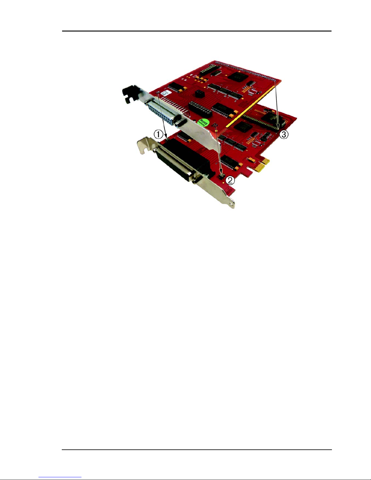
2.3 Fitting the Plug-on Boards
The boards should be handled with care in order to make sure that the
device is not damaged by electrostatic discharge (ESD), mechanical stress
or unsuitable current surges. Precautions should also be taken to avoid an
electric shock. Ensure that standard ESD safty precautions are taken. At
least one hand should be grounded in order to dissipate any static charge.
Observe the following procedure:
1. If the basic board is installed, you must first remove it in order
to be able to insert the plug-on board. Here you should
observe the procedure as described in the manual for your PC
system.
2. Make sure that electrostatic discharges cannot take place
through the plug-on board or the basic board as you plug it in.
Follow the standard ESD safty precautions.
3. Push the plug-on board carefully, and with only a little force,
on to the male connector provided for it (see diagram 1, items
1, 2 and 3). Check that the board is fully plugged in.
4. Choose two adjacent slots for the installation. If necessary,
remove any additional blanking plate for the slot of the plug-
on board.
5. Carefully plug the combination of the basic and plug-on
board into the computer.
6. Screw the two slot brackets down firmly.
7. Close the PC system again.
Manual ME-5004 Rev. 1.2E
Meilhaus Electronic Seite 13 Initial Operation
Diagram 1: Fitting the plug-on boards

Rev. 1.2E Manual ME-5004
Initial Operation Seite 14 Meilhaus Electronic

Manual ME-5004 Rev. 1.2E
Meilhaus Electronic Seite 15 Hardware
3 Hardware
3.1 Block Diagram
Diagram 2: Block diagram of the ME-5004
Pinout diagram of the 37-pin D-sub female connector in the appendix
(see „Pinout” on page 39).
In the following chapters you will learn more about the external wiring
of the individual subdevices. Chapter 4from page 23 describes the ope-
ration modes and the programming.
37-pin D-sub female
IRQ
Local address/data bus to base board
Basis board
Interrupt logic
ME-5004 ME-5810
Subdevice 0
Subdevice 1
FO (impulse generator)
Bit-pattern change
Bit-pattern compare
FI (freq. measurement)
DI (single)
DI_0..15
DO_0..15 Temperature monitoring
Current limitation
Source driver
Sink driver
DO (single)
Sink/source
selection
Iconst

Rev. 1.2E Manual ME-5004
Hardware Seite 16 Meilhaus Electronic
3.2 ME-5004 cPCI/PCIe
Diagram 3: ME-5004 cPCI/PCIe
ST1
ME-5004
REV.: 1.2
cPCIPCIe
F3
F1
F2

Manual ME-5004 Rev. 1.2E
Meilhaus Electronic Seite 17 Hardware
3.3 Digital Input/Output
The opto-isolated inputs and outputs have been designed for applications
in industrial control applications (typ. 24 V). An external power supply
(pin: VCC_EXT) is required for the opto-isolated digital outputs. De-
pending on the application, the drivers of the output ports can be
configured as sink or source or high impedance via software. The isola-
tion voltage to PC-ground is 1000 VACRMS.
The plug-on board of type ME-5004 has 16 opto-isolated inputs and 16
opto-isolated outputs. Due to the opto-isolation, the port direction is
fixed.
The programming of the various operating modes is described in chapter
4.1 from page 25.
3.3.1 Opto-isolated Inputs
The ME-5004 has 16 opto-isolated inputs which have been designed for
an input high-level Uin,H von typisch 24 V. A reference to the ground of
the external circuitry via GND_EXT (pins 15) has to be setup in any
case. The input lines show logic “0” if not connected.
Diagram 4: Inputs of the ME-5004
DI_Ax
GND_EXT
Uin,H =
Vcc
I
in=
5.5 mA
GND_PC
U
RWM
= 30V
24V (typ.)
R
v
= 4,5kΩ
(DI_Cx)

Rev. 1.2E Manual ME-5004
Hardware Seite 18 Meilhaus Electronic
The opto-isolated digital-inputs of the ME-5004 are protected from
overvoltages with special Z-diodes, so called Transient Voltage Suppres-
sor diodes (TVS diodes). These diodes can discharge short voltage pulses
with URWM (Reverse Working Maximum) greater than 30 V to ground
(max. 600 W pulse power at a pulse width of 1 ms).
3.3.2 Opto-isolated Outputs
The ME-5004 has 16 opto-isolated outputs. The output port is equipped
with special driver chips that allow a selection of sink and source via soft-
ware. Depending on the application, the user can switch between low-
active outputs (sink driver = standard setting) and high-active outputs
(source driver) via software. Moreover, the outputs can be set to high
impedance port-wise. A reference to the ground of the external wiring via
GND_DO (pin 21) has to be setup in any case.
3.3.2.1 Sink Driver
Each output port is equipped with two sink driver chips of type
ULN2803; detailed specifications see page 34.
Diagram 5: ME-5004 outputs with sink drivers
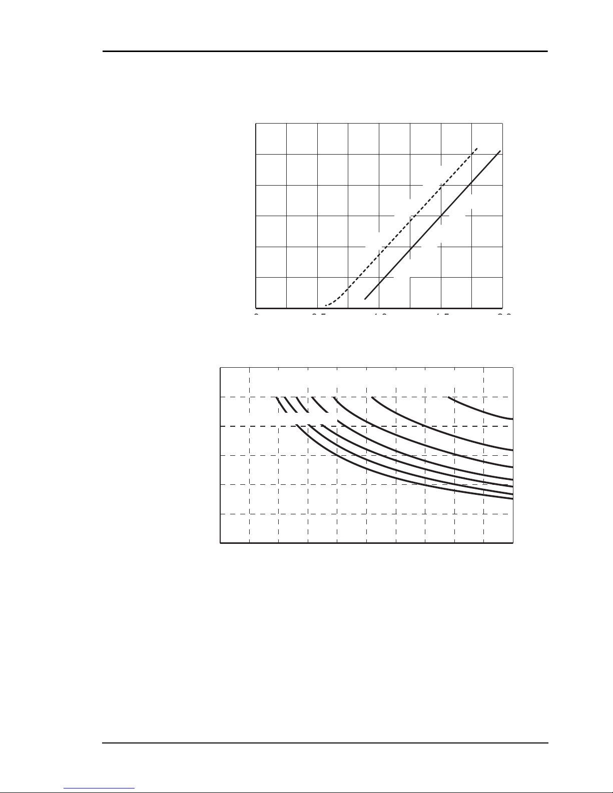
The maximum current per output (IC =ISink) depends on the saturation
voltage UCE and is limited by the power loss of the sum of the channels
on Ptot = 1 W per chip (DO_0…7 = chip 1, DO_8…15 = chip 2), see
diagram 6 and 7.
VCC_EXT
= ULmax
GND_DO
GND_PC
Signal
CX
Load
Sink driver
DO_x
ISink
Uext = 15…30V
RL
UCE
Manual ME-5004 Rev. 1.2E
Meilhaus Electronic Seite 19 Hardware
Ptot = P0+ … + P7≤1W (per chip at 70°C)
with P0= IC0 · UCE0
Diagram 6: Collector current against saturation voltage
Diagram 7: Collector current against duty cycle and number of active
channels in use
To supply the sink output drivers, an external power supply has to be
connected to VCC_EXT (Pin 1, 2, 20) with sufficient power (depending
on the application). At full load this means up to 0.5 A per channel for
the ME-5004.
Collector current IC[mA]
0
0
600
500
400
300
200
100
20151005
max. saturation voltage
typ. saturation voltage
Max. collector current IC[mA]
Number of simultaneously driving channels:
8 7 6 5 4 3 2
0
0
600
500
400
300
200
100
100908070605040302010
Duty cycle [%]
Recommended max.
current
Rev. 1.2E Manual ME-5004
Hardware Seite 20 Meilhaus Electronic
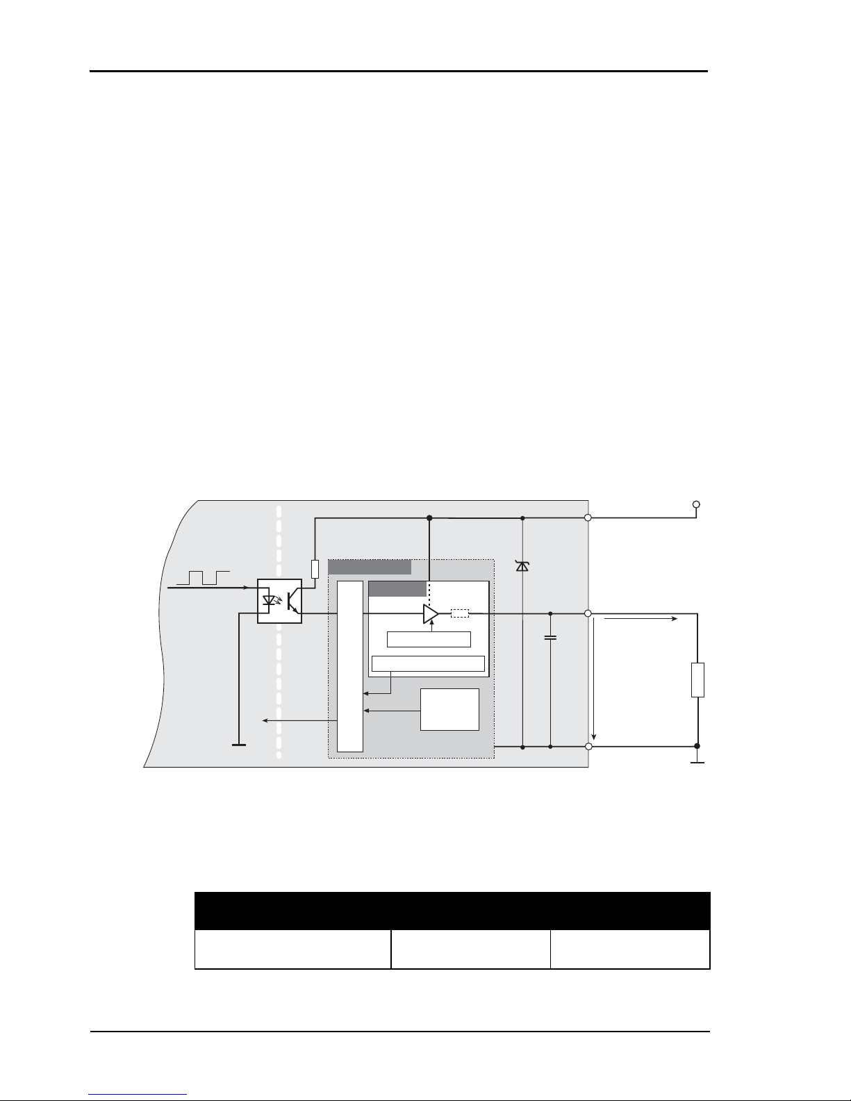
3.3.2.2 Source Driver
Each input port is equipped with two source driver chips of type
ISO1H811G; detailed specifications see page 34.
The source output drivers are short-circuit-proof and are equipped with
a current limiting per channel. The combination of current limiting,
thermal shutdown, and automatic re-start protects the circuitry against
overload. In the case of an overload condition (TTSD = typ. 175°C) the
related channel will switch off and on again automatically, as soon as the
junction temperature has fallen below the threshold of TR= 135°C. If a
chip temperature of typ. 130°C is still exceeded, the overloaded channel
remains disabled and is only reactivated, if the temperature decreases
below TCR = 110°C. Channels in standard (no overload) condition can
be used at any time without restrictions. In the case of an overload condi-
tion the output driver (per port) can send an interrupt to the PC. A
further security feature is a complete disabling of a port in case of a mis-
sing ground connection.
Diagram 8: ME-5004 outputs with source drivers
The following table shows the maximum output current IOut in
dependency of the number of channels in use:
Number of channels used 116
IOut [A] 0.625 A 0.5 A
Ta b l e 2: Max. current of the source drivers
VCC_EXT
DO_x
GND_DO
GND_PC
Signal
Uout,H
(Uext = 15…30V)
Iout
Current limitation CX
Load
Interrupt
Housing-
temperature
Logic
Junction temperature
Per channel
Chip (2 per port)
Source driver
RON
RL
Other manuals for ME-5004
1
Table of contents
Other Meilhaus Electronic Motherboard manuals


