MicroArm MINI2440 User manual

High Performance Low Cost Embedded Systems
Copy right reserved © MicroArm Systems, Inc. 1612 2nd Ave.SWPMB#108,Cullman,AL35055 -1-
Website : www.microarmsystems.com
MINI2440 User’s Manual
2009-03-03
copyright@2007-2009
High Performance Low Cost Embedded Systems
Copy right reserved © MicroArm Systems, Inc. 1612 2nd Ave.SWPMB#108,Cullman,AL35055 -2-
COPYRIGHT STATEMENT
The Chinese version of this manual is copyright © Friendly ARM.
Acknowledgement is made to Friendly ARM for permission to translate
and use the Chinese manual’s content (content being images, text, programs and
scripts).
The content (content being images, text, programs and scripts) of this
English manual is copyright © Micro Arm Systems, Inc. All rights expressly
reserved.
Any content of the manual printed or downloaded may not be sold,
licensed, transferred, copied or reproduced in whole or in part in any manner or
in or on any media to any person without the prior written consent of Micro
Arm Systems, Inc. including but not limited to:
transmission by any method
storage in any medium, system or program
display in any form
performance
hire, lease, rental or loan
Requests for permission to reproduce material from this manual should be
addressed to Micro Arm Systems, Inc.

High Performance Low Cost Embedded Systems
Copy right reserved © MicroArm Systems, Inc. 1612 2nd Ave.SWPMB#108,Cullman,AL35055 -3-
Table of Contents
Chapter 1 Introduction............................................................................................................................................... 7
1.1 About this Manual........................................................................................................................................ 7
1.2 Benefits........................................................................................................................................................ 7
1.3 Product Overview........................................................................................................................................ 7
1.3.1 What a MINI2440 Development Board Looks Like......................................................................... 7
Chapter 2 Getting Started ........................................................................................................................................ 12
2.1 System Setup and Configurations.............................................................................................................. 12
2.1.1 Boot Options................................................................................................................................... 12
2.1.2 Connecting Peripherals................................................................................................................... 12
2.1.3 Setting up Super Terminal .............................................................................................................. 12
2.2 Power Up................................................................................................................................................... 15
2.2.1 Entering BIOS ................................................................................................................................15
2.2.2 Installing USB Driver..................................................................................................................... 16
2.2.3 Entering Main Menu....................................................................................................................... 22
2.2.4 Sub Menus...................................................................................................................................... 25
2.2.5 Setting Linux Booting Parameters.................................................................................................. 29
2.3 Board Device Testing................................................................................................................................. 33
2.3.1 Downloading Testing Utilities........................................................................................................ 34
2.3.2 Device Testing ................................................................................................................................39
Chapter 3 Running Linux ........................................................................................................................................ 50
3.1 Software Applications and Configurations in Linux Qtopia...................................................................... 50
3.1.1 Calibrating Touch Screen................................................................................................................ 50
3.1.2 Main Interface................................................................................................................................. 51
3.1.3 Playing MP3 ................................................................................................................................... 53
3.1.4 Playing Video.................................................................................................................................. 54
3.1.5 Browsing Pictures........................................................................................................................... 55
3.1.6 Auto Mounting SD and USB Drives............................................................................................... 57
3.1.7 Calculator........................................................................................................................................ 58
3.1.8 Command Line ............................................................................................................................... 59
3.1.9 File Browser.................................................................................................................................... 60
3.1.10 Configuring Network.................................................................................................................... 61
3.1.11 Testing Ping .................................................................................................................................. 62
3.1.12 Browser......................................................................................................................................... 63
3.1.13 Testing LED.................................................................................................................................. 64
3.1.14 Testing EEPROM ......................................................................................................................... 65
3.1.15 PWM Buzzer ................................................................................................................................66
3.1.16 Serial Port Assistant...................................................................................................................... 67
3.1.17 Audio Recording........................................................................................................................... 70
3.1.18 Using USB Camera....................................................................................................................... 71

High Performance Low Cost Embedded Systems
Copy right reserved © MicroArm Systems, Inc. 1612 2nd Ave.SWPMB#108,Cullman,AL35055 -4-
3.1.19 Using CMOS Camera................................................................................................................... 72
3.1.20 Testing LCD.................................................................................................................................. 73
3.1.21 Backlight Control.......................................................................................................................... 74
3.1.22 A/D Conversion ............................................................................................................................ 75
3.1.23 Testing User Buttons..................................................................................................................... 76
3.1.24 Testing Touch Pen......................................................................................................................... 77
3.1.25 Barcode Scanning......................................................................................................................... 79
3.1.26 Language Setting.......................................................................................................................... 79
3.1.27 Setting up Time Zone, Date, Time andAlarm Clock.................................................................... 81
3.1.28 Rotating Screen............................................................................................................................. 82
3.1.29 Setting up Auto Run Programs ..................................................................................................... 83
3.1.30 System Shutdown ......................................................................................................................... 85
3.1.31 Watchdog ...................................................................................................................................... 86
3.2 Operating MINI2440 Linux via Super Terminal ....................................................................................... 87
3.2.1 Mounting a USB Drive/Portable Hard Disk................................................................................... 88
3.2.2 Mounting a SD Card....................................................................................................................... 90
3.2.3 Mounting a CMOS Camera............................................................................................................ 92
3.2.4 File Transfers to and from a PC via a Serial Port............................................................................ 93
Chapter 4 Running WinCE...................................................................................................................................... 96
4.1 Software Applications and Configurations in WinCE ............................................................................... 96
4.1.1 Playing MP3 ................................................................................................................................... 96
4.1.2 File Transfer with FTP.................................................................................................................... 96
4.1.3 Configuring Web Server ................................................................................................................. 97
4.2 Testing Hardware in WinCE...................................................................................................................... 98
4.2.1 Mounting a USB Drive................................................................................................................... 98
4.2.2 Mounting a SD Card....................................................................................................................... 99
4.2.3 Connecting a USB Device via ActiveSync..................................................................................... 99
4.2.4 Testing Serial Ports....................................................................................................................... 100
Chapter 5 Setting up Linux Development Environment........................................................................................ 102
5.1 Setting up Fedora 9.0 Development Environment................................................................................... 102
5.1.1 Installing Fedora 9.0 ..................................................................................................................... 102
5.2 Basic Configurations and Applications.................................................................................................... 128
5.2.1 Adding a New User Account ........................................................................................................ 128
5.2.2 Accessing Windows Files ............................................................................................................. 132
5.3 Setting up Cross Compile Environment .................................................................................................. 137
5.4 Uncompressing Source Code and Installing Application Utilities........................................................... 140
5.4.1 Uncompressing Source Code........................................................................................................ 140
5.4.2 Creating Target File System.......................................................................................................... 142
5.4.3 Uncompressing Application Utilities............................................................................................ 142
5.4 Configuring NFS Service ........................................................................................................................ 144
5.4.1 Setting up Shared Directories....................................................................................................... 144
5.5.2 Starting NFS ................................................................................................................................. 144
5.5.3 Booting System via NFS............................................................................................................... 146

High Performance Low Cost Embedded Systems
Copy right reserved © MicroArm Systems, Inc. 1612 2nd Ave.SWPMB#108,Cullman,AL35055 -5-
Chapter 6 Setting up WinCE Development Environment ..................................................................................... 149
6.1 Setting up WinCE 5.0 Development Environment.................................................................................. 149
6.1.1 Installing Platform Builder 5.0 (Including 2007 Patches) ............................................................ 149
6.1.2 Installing BSP............................................................................................................................... 160
6.1.3 Compiling Kernel ......................................................................................................................... 162
6.1.4 Exporting SDK............................................................................................................................. 166
6.1.5 Installing Embedded Visual C++.................................................................................................. 172
6.1.6 Installing EVC Patches and Exported SDK.................................................................................. 178
6.1.7 Configuring WinCE Kernel.......................................................................................................... 187
Chapter 7 System Backup and Reinstallation........................................................................................................ 201
7.1 System Backup and Reinstall .................................................................................................................. 201
7.1.1 System Backup ............................................................................................................................. 201
7.1.2 System Restore ............................................................................................................................. 205
7.2 Installing Linux........................................................................................................................................ 208
7.2.1 Partition ........................................................................................................................................ 208
7.2.2 Installing Bootloader .................................................................................................................... 209
7.2.3 Installing Linux Kernel................................................................................................................. 211
7.2.4 Installing Root File System........................................................................................................... 212
7.3 Installing WinCE ..................................................................................................................................... 214
7.3.1 Partition ........................................................................................................................................ 214
7.3.2 Installing Bootloader .................................................................................................................... 216
7.3.3 Installing Eboot............................................................................................................................. 217
7.3.4 Installing WinCE Kernel............................................................................................................... 218
Appendix A: Resources in Shipped CD................................................................................................................. 222
Appendix B: Schematics and Device Details........................................................................................................ 223
Board Schematic............................................................................................................................................ 223
Address Space................................................................................................................................................ 224
SDRAM......................................................................................................................................................... 225
FLASH .......................................................................................................................................................... 226
Power System................................................................................................................................................ 227
Reset System.................................................................................................................................................. 230
User LED....................................................................................................................................................... 231
User Test Keys............................................................................................................................................... 232
A/D Input Test ............................................................................................................................................... 233
PWM Buzzer ................................................................................................................................................. 234
Serial Port...................................................................................................................................................... 235
USB Interface................................................................................................................................................ 236
LCD Interface................................................................................................................................................ 237
EEPROM....................................................................................................................................................... 239
Network Interface.......................................................................................................................................... 240
Audio Interface.............................................................................................................................................. 241
JTAG Interface............................................................................................................................................... 242
GPIO.............................................................................................................................................................. 243

High Performance Low Cost Embedded Systems
Copy right reserved © MicroArm Systems, Inc. 1612 2nd Ave.SWPMB#108,Cullman,AL35055 -6-
CMOS Camera Interface ............................................................................................................................... 244
System Bus.................................................................................................................................................... 245

High Performance Low Cost Embedded Systems
Copy right reserved © MicroArm Systems, Inc. 1612 2nd Ave.SWPMB#108,Cullman,AL35055 -7-
Chapter 1 Introduction
1.1 About this Manual
This manual is intended to provide the user with an overview of the MINI2440 board, its benefits,
features, specifications, and set up procedures.
1.2 Benefits
The MINI2440 Development Board is based on the Samsung S3C2440 microprocessor. Its PCB is 4-layer
boarded, equipped with professional equal length wiring which ensures signal integrity. All MINI2440
boards are manufactured in mass production and released with strict quality control. On startup it directly
boots preinstalled Linux by default. There are no extra setup steps or configuring procedures to start the
system. It is easy for users to get started. Anyone with very basic knowledge about the C language can
become proficient in its development within two weeks. This package also provides detailed documents on
how to configure and boot to alternative operating systems. In addition, our technical support is always
available for assistance to our customers. This product delivers high quality with low price.
For the latest version of this manual please visit www.microarmsystems.com.
1.3 Product Overview
1.3.1 What a MINI2440 Development Board Looks Like
The MINI2440 development board is a 100 x 100(mm) board equipped with a wide variety of
connectors, interfaces and ports.

High Performance Low Cost Embedded Systems
1.3.2 MINI2440 Hardware Features
CPU
- Samsung S3C2440A,400MHz,maximum 533Mhz
SDRAM
- On board 64M SDRAM
- 32bit Data Bus
- SDRAM, maximum clock frequency 100MHz
FLASH Memory
-On board 64M Nand Flash
-On board 2M Nor Flash with preinstalled BIOS
LCD
- Four-wire touch screen interface
Copy right reserved © MicroArm Systems, Inc. 1612 2nd Ave.SWPMB#108,Cullman,AL35055 -8-

High Performance Low Cost Embedded Systems
Copy right reserved © MicroArm Systems, Inc. 1612 2nd Ave.SWPMB#108,Cullman,AL35055 -9-
- Support black and white, 4 level grayscale, 16 level grayscale, 256-color、4096-color STN
LCD, 3.5-inch to 12.1-inch, screen resolution 1024x768;
- Support black and white, 4 level grayscale, 16 level grayscale, 256-color, 64K-color, true
color TFT LCD, 3.5-inch to 12.1-inch, screen resolution 1024x768,
- NEC 256K color 240x320/3.5-inch TFT true color touch screen,
- 12 V power supply interface, it is for 12V CCFL backlight modules of big size TFT LCDs
1.3.3 Interfaces and External Accessories
Interfaces and ExternalAccessories
- 100M Ethernet RJ-45 port (powered by the DM9000 network chip)
- 3 serial ports
- USB Host port
- USB Slave B port
- SD card interface
- Single stereo audio output and single microphone interface
- 2.0mm 10 pin JTAG interface
- 4 USER LEDs
- 6 USER Buttons (with leads to block)
- PWM buzzer
- Adjustable resistor, for AD conversion
- AT24C08 chip with I2C Bus, for I2C Bus test
- 2.0 mm 20pin video camera interface
- Onboard real-time clock backup battery
- 5V power supply interface, with power switch and led
System Clock Source
- 12M passive crystal oscillator
Real-Time Clock
- RTC with lithium battery backup
Extended Interfaces
-34 pin 2.0mm GPIO port
-40 pin 2.0mm system bus interface
1.3.4 OS Support
The MINI2440 development board currently supports Linux 2.6.29 and WinCE.NET 5.0.
1.3.4.1 Linux Features
Kernel Version
- Linux 2.6.29
File Systems
-YAFFS2
-CRAMFS
-EXT2
-FAT32

High Performance Low Cost Embedded Systems
Copy right reserved © MicroArm Systems, Inc. 1612 2nd Ave.SWPMB#108,Cullman,AL35055 -10-
-NFS
Drivers (all open source)
-Drivers for 3 serial ports
-DM9000 driver
-Audio driver (UDA1341) (audio recording supported)
-RTC driver
-User LED driver
-USB host driver
-True color LCD driver (including 1024 x 768 VGA)
-Touch screen driver
-USB camera driver
-Drivers for USB mouse, keyboard, flash drive and portable hard disk
-SD card driver, supports maximum memory of 32 G
-I2C-EEPROM driver
-PWM buzzer driver
-LCD backlight driver
-A/D converter driver
-Watchdog driver (watchdog reset is cold reset)
Linux Applications and Utilities
-Busybox1.13 (Linux tool kit including basic Linux commands)
-Telnet, FTP and inetd (remote login tool)
-BOA (web server)
-Madplay (console based mp3 player)
-Snapshot (console based screen print tool)
-ifconfig, ping, route and so on (basic network commands)
Graphic User Interface (Open Source)
-Qt/Embedded 2.2 (x86 and arm)
Qtopia Test Utilities (developed by FriendlyARM, not open source)
-A/D conversion test tool
-LED test tool
-User button test tool
-I2C-EEPROM read/write test tool
-LCD test tool
-Ping test tool
-USB camera live preview and picture taking
-Audio recorder
-Web browser
-Watchdog test tool
-Network configuration tool
-Backlight control tool
-Language setting tool (English and Chinese)
-Handwriting tool (for touch pen testing)
-MMC/SD card and flash drive auto mounting and unmounting

High Performance Low Cost Embedded Systems
Copy right reserved © MicroArm Systems, Inc. 1612 2nd Ave.SWPMB#108,Cullman,AL35055 -11-
1.3.4.2 WinCE Features
Version
- Windows CE.net 5.0
Features
-DM9000 driver source code
-Drivers for USB keyboard, mouse, flash drive and portable hard disks
-Drivers for 3 serial ports
-USB ActiveSync
-Audio driver
-SD card driver
-RTC clock
-Registry archive
-Power-down data save in flash drive
-Screen rotation
Default System Options (Simplified Chinese System)
-XP screen
-Windows Media Player 9.0 (supporting mp3, mpeg2, mpeg4, wma, wav and so on)
-Super player (video player)
-Picture browser and word pad
-IE6
-FTP, TELNET and HTTPD
-Serial port assistant
1.3.5 Additional Resources
Please refer to Appendix A for the resources included in the shipped CD and Appendix B for the
device schematics.
High Performance Low Cost Embedded Systems
Copy right reserved © MicroArm Systems, Inc. 1612 2nd Ave.SWPMB#108,Cullman,AL35055 -12-
Chapter 2 Getting Started
2.1 System Setup and Configurations
2.1.1 Boot Options
You can select the booting mode by toggling the S2 switch:
When toggling the S2 switch to the “Nor Flash” side the system will boot from on board Nor
Flash. When toggling the S2 switch to the “Nand Flash” side the system will boot from on board
Nand Flash.
This board is shipped with the switch toggled to the Nand Flash side by default it will boot from
Nand Flash. Both its Nor Flash and Nand Flash have been installed an identical BIOS (which
supports both types of Flash. The only difference is that the system will have different startup
windows).
2.1.2 Connecting Peripherals
Connect the MINI2440 board’s serial port to a PC’s serial port with the shipped serial
cable in the package
Connect the MINI2440 board’s Ethernet interface to a PC with the shipped crossover
cable
Connect the shipped 5V power supply adapter to the 5V power supply interface on the
board
Connect a headphone or speaker to the audio input(green) on the board
Connect an LCD touch panel (if the user has one) to the LCD interface on the board
following the data bus’arrow.
Connect the MINI2440 board to a PC with a USB cable.
2.1.3 Setting up Super Terminal
To connect the MINI2440 board to a host PC via a serial cable, you should use a simulated
terminal. There are many tools available. A most widely used one is the MS-Windows’ super
terminal. In Windows9x, you need to install it by checking that option during installation.
Windows2000 and later versions already have it installed by default. We used the super terminal in
Windows XP in all our examples in this manual (Other versions of super terminal might have
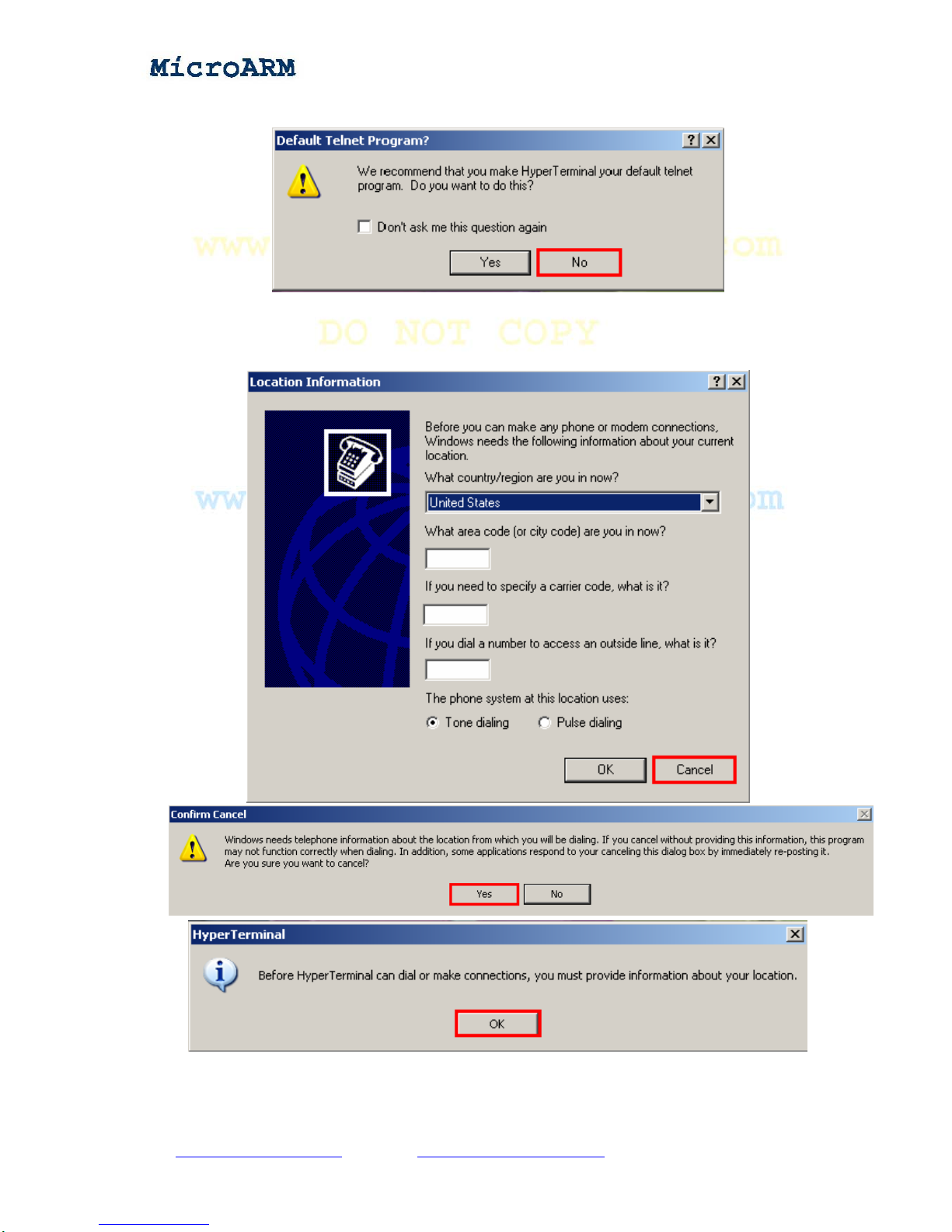
different user interfaces). Go to “Start” -> “All Programs” -> “Accessories” -> “Communications”.
High Performance Low Cost Embedded Systems
Click on “Hyper Terminal” and a Window will pop up as below. Click on the “No” button
Click on the “Cancel” button on the following window
Click on the “Yes” button and the “OK” button to the next step
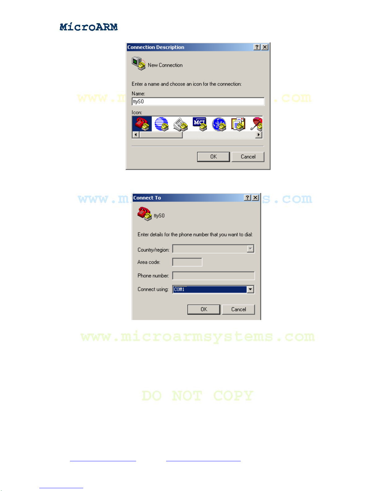
A popup window will require you to name this connection. In this example we typed “ttyS0”.
Windows does not accept names like “COM1” that have already been used by the system.
Copy right reserved © MicroArm Systems, Inc. 1612 2nd Ave.SWPMB#108,Cullman,AL35055 -13-
High Performance Low Cost Embedded Systems
After naming this connection another window will require you to select a serial port that will be
used to connect the MINI2440 board. Here we selected COM1:
Lastly, also the most important step is to set up the port properties. Note: you must select “No” in
the data flow control field otherwise you will only be able to see outputs. In addition the bits per
second should be set to 115200.
After setting up all properties, turn on the board’s power supply, if the connection gets set
properly, you will see a VIVI startup interface. If everything runs fine, please save this connection
for later use
Copy right reserved © MicroArm Systems, Inc. 1612 2nd Ave.SWPMB#108,Cullman,AL35055 -14-

High Performance Low Cost Embedded Systems
2.2 Power Up
2.2.1 Entering BIOS
The board is shipped with a preinstalled SUPERVIVI in Nor Flash. When the system boots from
Nor Flash it will enter the BIOS and in the meantime the green LED1 on the board will be
flashing. The startup interface is as below:
Copy right reserved © MicroArm Systems, Inc. 1612 2nd Ave.SWPMB#108,Cullman,AL35055 -15-

High Performance Low Cost Embedded Systems
SUPERVIVI is developed and maintained by FriendlyArm, it is based on vivi. It starts with a
function menu. And users can switch between supervivi’s menu interface and command line.
Supervivi can be burned into the Nor Flash with JTAG or run from the Nand Flash. When it is
burned into the Nor Flash and run, users will see its menu. When it is run from the Nand Flash it
will start as command line (note: users need to press down and hold the space key in the super
terminal on system startup otherwise the system will boot to its installed operating system).
Supervivi is mainly for software burning and debugging, and can be used to partition flash drive. It
downloads files via USB. It is easy to use and runs fast. When burning supervivi into the Nor Flash,
you can easily update your Linux or WinCE system, or any other operating system that supports
system boot from the Nand Flash and non OS programs to the Nand Flash such as uCos2, U-boot,
Nboot, 2440test and so on, and then reboot system from the Nand Flash to enjoy your programs.
When burning supervivi to the Nand Flash, it will self detect your operating system and start it. In
addition, with its “Down & Run” function, you can download programs to RAM and run them. This
features software debugging such that you don’t need a simulator. The 2440test utility in the
shipped CD is such a good example.
With supervivi, you can download the Linux kernel image zImage into RAM and run it. You can
even start your system via network by setting up the network boot parameters in supervivi.
Similarly, you can download the WinCE kernel image NK.nb0 to RAM and run it too.
2.2.2 Installing USB Driver
Note: the driver installed here can only work for a USB connection in the BIOS mode. It should
work in conjunction with the dnw.exe executable. After the system enters Linux or WinCE, the
Copy right reserved © MicroArm Systems, Inc. 1612 2nd Ave.SWPMB#108,Cullman,AL35055 -16-
Website : www.microarmsystems.com Email: service@microarmsystems.com Phone: 1-888-417-9266

High Performance Low Cost Embedded Systems
driver will no longer be used.
Installing this USB driver doesn’t need to connect to a board. It is just for the PC system.
Open the shipped CD, double click on “windows 平台工具\usb 下载驱动\ FriendlyARM
USB Download Driver Setup_20090421.exe” to start installing.
The following window will show up:
Click on (“Next”)the middle button.
Copy right reserved © MicroArm Systems, Inc. 1612 2nd Ave.SWPMB#108,Cullman,AL35055 -17-
Website : www.microarmsystems.com Email: service@microarmsystems.com Phone: 1-888-417-9266

High Performance Low Cost Embedded Systems
A warning message will pop up
Click on the (“continue anyway”) the left button to finish the installation.
Copy right reserved © MicroArm Systems, Inc. 1612 2nd Ave.SWPMB#108,Cullman,AL35055 -18-
Website : www.microarmsystems.com Email: service@microarmsystems.com Phone: 1-888-417-9266

High Performance Low Cost Embedded Systems
Now let’s test the USB connection:
Connect the MINI2440 board to a host PC via a USB cable. Toggle the S2 switch to the
“Nor Flash” side.
Turn on the S1 switch, if this is the first time you connect, Windows XP will prompt that a new
USB device is found. Follow the steps below to install a USB driver:
(1) After the following window pops up, check the third option and click on the “Next” button
Copy right reserved © MicroArm Systems, Inc. 1612 2nd Ave.SWPMB#108,Cullman,AL35055 -19-
Website : www.microarmsystems.com Email: service@microarmsystems.com Phone: 1-888-417-9266

High Performance Low Cost Embedded Systems
(2) On the window shown below, check the first option and click on the “Next” button
On the following popup window, click on the left button (“Continue anyway”).
So far, our installation is done.
Copy right reserved © MicroArm Systems, Inc. 1612 2nd Ave.SWPMB#108,Cullman,AL35055 -20-
Website : www.microarmsystems.com Email: service@microarmsystems.com Phone: 1-888-417-9266
Table of contents
Popular Motherboard manuals by other brands


Supero
Supero SUPER S2DG2 User's and bios manual

Freescale Semiconductor
Freescale Semiconductor Babbage 2.5 Startup guide

Angel Medical Systems
Angel Medical Systems Guardian Prog-003 Setup & operation guide

EVGA
EVGA Z97 Brochure & specs

Gigabyte
Gigabyte B550 AORUS ELITE AX user manual

STMicroelectronics
STMicroelectronics LED7707 Application note


