MELAG MELAtherm 10 Evolution User manual

Technical Manual
MELAtherm® 10 Evolution
Washer-Disinfector
from software version 3.0.20
EN
Read this manual carefully and in the correct order before setting up and commissioning the device. The instructions in-
clude important safety information. You also receive a User Manual with the device. Please store this manual and the
user manual carefully and in close proximity to the device. They represent a component of the product.


Contents
Contents
1 General guidelines ...............................................................................................................................................................5
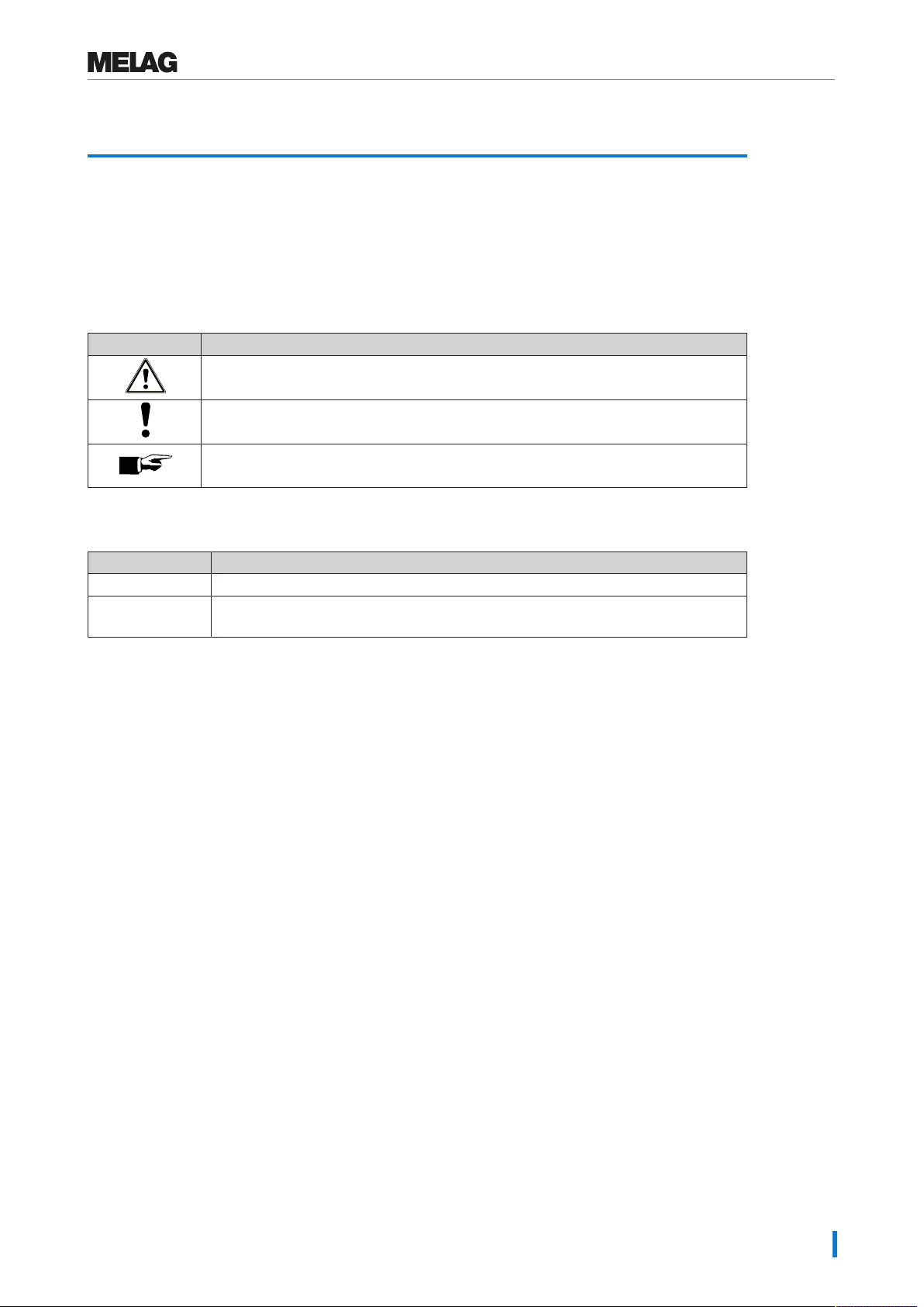
Symbols used.......................................................................................................................................................................5
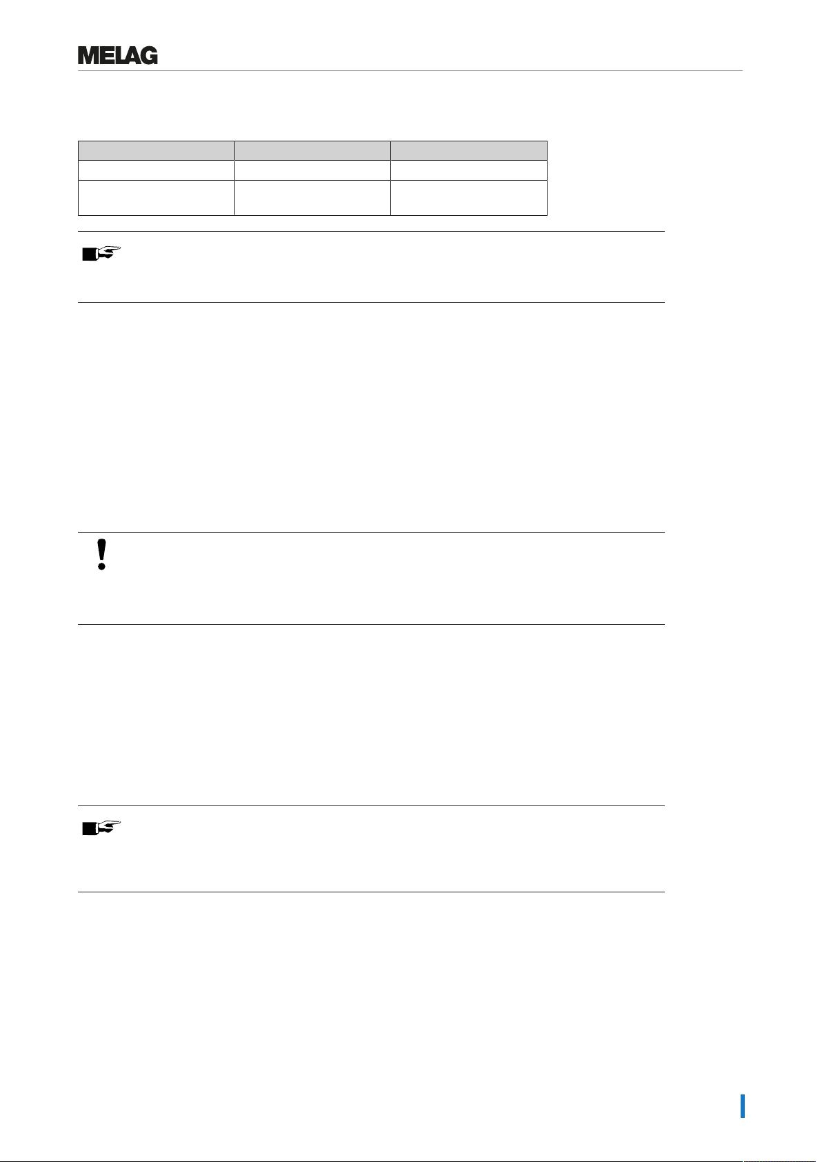
Formatting rules ...................................................................................................................................................................5
2 Installation requirements.....................................................................................................................................................6
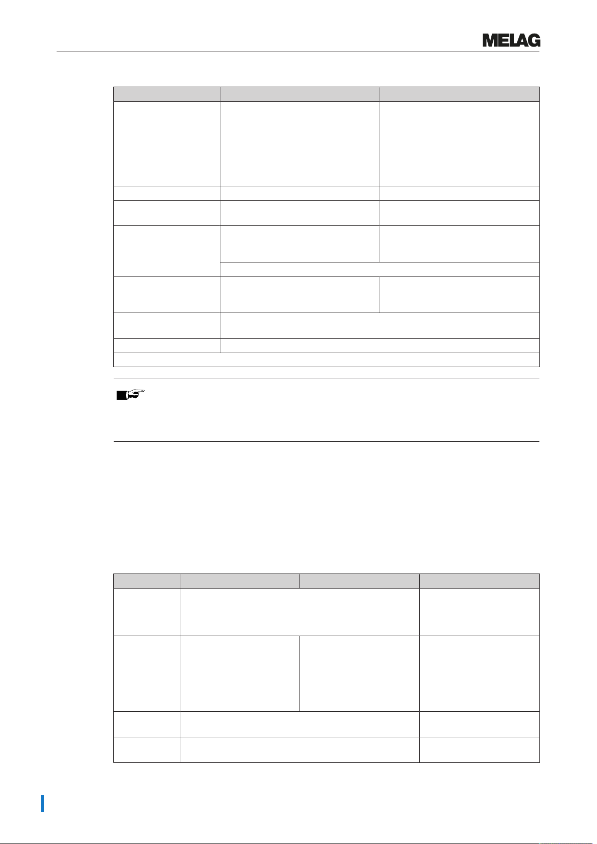
Space requirements .............................................................................................................................................................6
Installation location...............................................................................................................................................................7
On-site requirements............................................................................................................................................................9
3 Setup and installation ........................................................................................................................................................12
Removing from the packaging ...........................................................................................................................................12
Removing the stainless steel cover plate...........................................................................................................................14
Aligning the device horizontally..........................................................................................................................................14
Aligning the device with floor unit.......................................................................................................................................15
4 Commissioning...................................................................................................................................................................18
Date and time.....................................................................................................................................................................18
Logging ..............................................................................................................................................................................18
Filling the regeneration salt ................................................................................................................................................18
Determining the water hardness ........................................................................................................................................18
Regeneration......................................................................................................................................................................18
Filling process agents ........................................................................................................................................................18
Checking the metering concentration.................................................................................................................................19
Bleeding the metering system............................................................................................................................................19
Checking the metering accuracy........................................................................................................................................19
Exceptions when setting up at altitudes .............................................................................................................................21
Resetting the maintenance counter ...................................................................................................................................22
Checklist.............................................................................................................................................................................22
Validation ...........................................................................................................................................................................22
5 Process-relevant parameters (VRP) .................................................................................................................................23
Universal-Program .............................................................................................................................................................23
Quick-Program ...................................................................................................................................................................24
Intensive-Program..............................................................................................................................................................25
Ophthalmo-Program...........................................................................................................................................................26
Rinsing ...............................................................................................................................................................................27
6 Settings ...............................................................................................................................................................................28
Menu overview ...................................................................................................................................................................28
Setting the IP address........................................................................................................................................................29
Selecting the connection via FTP or TCP ..........................................................................................................................30
7 Frequently Asked Questions (FAQ)..................................................................................................................................32
How to open and print a log? .............................................................................................................................................32
What does the log name mean? ........................................................................................................................................33
How to format a CF card in the device?.............................................................................................................................34
How to format a CF card on the computer correctly? ........................................................................................................35
How to integrate the device in a (practice) network? .........................................................................................................35
How to set up the FTP server? ..........................................................................................................................................36

Contents
What do the terms IP address, subnetwork and DHCP mean? .........................................................................................37
How to determine the software version of the device? ......................................................................................................37

1 General guidelines
5
1 General guidelines
Read this manual carefully and in the correct order before setting up and commissioning the device. The
instructions include important safety information. You also receive a User Manual with the device. Please
store this manual and the user manual carefully and in close proximity to the device. They represent a
component of the product.
Symbols used
Symbol Explanation
Indicates a dangerous situation, which if not avoided, could entail slight to life-
threatening injuries.
Draws your attention to a situation, which if not avoided, could result in damage to the
instruments, the practice fittings or the device.
Draws your attention to important information.
Formatting rules
Example Explanation
see Chapter 2 Reference to another text section within this document.
Universal-
Program
Words or phrases appearing on the display of the device are marked as display text.

2 Installation requirements
6
2 Installation requirements
Space requirements
A
B1
B2
B3
C
D
E
G
F
Fig.1: Fore view with floor unit and side view left
PLEASE NOTE
If the device is installed in an L-shaped corner, drawers to the left or right of the device
may be blocked and cannot open due to the protruding display unit.
Device dimensions Semi-integrated unit Free-standing Top-frame device*)
Width A 59.8cm 59.8cm 59.8cm
Height B B1 = 81.8cm B2 = 83.6cm B3 = 124cm
Depth (with
display)
C 68.1 cm 68.1 cm 68.1 cm
D 8.2cm 8.2cm 8.2cm
Depth (without
display)
E 59.1cm 59.1cm 59.1cm
F 28.5cm 28.5cm 28.5cm
G 96.1cm 96.1cm 96.1cm
Remarks -- Space requirements in
the working surface:
min. 60cm width,
60cm depth and
82cm height.
Free-standing using the
optionally-available
stainless steel cover plate
e.g. next to to the already
present under-desk
cabinets.
This enables a
particularly ergonomic
operation and loading of
the device. Provides
storage space, e.g. for up
to six 5l containers. The
stainless steel cover plate
can also be used.
*) Free-standing using the optionally-available stainless steel cover plate e.g. next to the already present
under-desk cabinets.
PLEASE NOTE
Avoid disturbing installations in the area of the device rear (such as hoses, cables, pipes,
sockets etc.).

2 Installation requirements
7
Additional space requirement when using a water treatment unit
Space is required above the MELAdem53 / MELAdem 53 C for clear access to the hose connections.
Dimensions MELAdem 53 MELAdem 53 C
Diameter 24cm 24cm
Height of the unit incl.
connecting parts
57cm 45cm
PLEASE NOTE
If the device is to be installed as a semi-integrated unit, the MELAdem53 /
MELAdem53C can be placed in an adjacent floor unit.
Installation location
Electromagnetic compatibility
When assessing the Electromagnetic Compatibility (EMC) of this device, the emitted interference threshold
values for Class B devices and the stability for operation in an electromagnetic environment as described
in IEC 61326-1 were taken as the basis.
The device is thus suitable for operation in all institutions and domestic settings connected to a public
mains power supply.
The floor should be made of wood or concrete or be tiled with ceramic tiling. If the floor is fitted with syn-
thetic material, the relative humidity must amount to a minimum of 30%.
NOTICE
Steam escaping from the device may cause damage at the adjacent furniture.
nDuring installation of the device please ensure that the adjacent base cabinets or other
furniture and fittings are resistant to condensation.
Set-up variations
You can set up the device in the following manner:
▪ Free-standing using the optional stainless steel cover plate.
▪ Next to pre-existing under-desk unit in conjunction with the optional stainless steel plate. Space
requirements amount to a minimum of 60cm in width and 60cm depth.
▪ As semi-integrated unit in a pre-existing cavity with a work surface.
▪ Free-standing using the optional stainless steel cover plate and additional floor unit.
PLEASE NOTE
If the device is to be set up with the additional floor unit, then the device must be secured
on the wall using the wall fixture (art. no. 21589), see separate instructions (doc.:
AS_025-17).

2 Installation requirements
8
Property MELAtherm 10 Evolution DTA/MELAtherm 10 Evolution DTB
Installation location Dry and protected from dust, free of vibrations and shocks. There are no
installations in area of the door back.
Installation surface Level and horizontal Irregularities of the ground of max. 1cm can be offset by
setting the device feet.
Max. altitude 1500 m (depending on the set up height, it may be necessary to reduce the
disinfection temperature, see Exceptions when setting up at altitudes
[}page21])
Waste heat (with max.
solid load)
0.98 kWh (3.5 MJ)
Ambient temperature 5-40 °C (recommended max. 25 °C)
Relative humidity max. 80 % at temperatures up to 31 °C, max. 50 % at 40 °C (decreasing in a
linear fashion)
Max. floor loading
(normal operation)
Semi-integrated unit: Free standing: Top-frame device:
40.7 kg per device foot 42.7 kg per device foot 63.7 kg per device foot
Installation free-standing
NOTICE
In case of an incorrect installation of the device, there may be malfunctions during
operation.
The specified installation heights must be complied with.
Requirements to construction-side wastewater connection for a semi-integrated unit or free-
standing device
Connection height Remarks
0.4-1m ---
<0.4m Installation in a curve to at least 0.4m height
Fig.2: Connection scheme without floor unit
1 DI water connection 4 Connection for water outlet at the syphon
2 Cold water inlet 5 Type F (SCHUKO) socket
3 Dirt trap water inlet 6 CEE socket
PLEASE NOTE
Due to the length of mains lead and water pipe a sinistral connection is recommended.

2 Installation requirements
9
Installation as a top-frame device
Requirements to construction-side wastewater connection for a top-frame device
Connection height Remarks
min. 0.74m ---
<0.74m Installation in a curve to at least 0.74m height
Fig.3: Connection scheme with floor unit
1 DI water connection 4 Connection for water outlet at the syphon
2 Cold water connection 5 Type F (SCHUKO) socket
3 Dirt trap water inlet 6 CEE socket
PLEASE NOTE
Due to the length of mains lead and water pipe a sinistral connection is recommended.
On-site requirements
WARNING
Improper connections can result in a short-circuit, fire, an electric shock or water
damage.
nThe connection of the electrical supply as well as the feed and wastewater connections are
to be made by trained personnel.
nComply with the specifications regarding the installation and first commissioning provided in
the user manual.
Mains supply
uNever damage or alter the power plug or cable.
uNever bend or twist the power cable.
uNever remove the plug by pulling on the power cable. Always take a grip on the plug.
uNever place any heavy objects on the power cable.
uNever run the power cable over areas in which it could become trapped (e.g. doors or windows).
uNever lead the cable along a source of heat.
uNever use any nails, paper fasteners or similar objects to fix the cable.
uShould the power plug or cable suffer damage, switch off the device. The power cable or plug should
only be replaced by authorized technicians.

2 Installation requirements
10
On-site requirements of the mains connection
MELAtherm 10 Evolution DTA MELAtherm 10 Evolution DTB
Local requirements Electrical equipment must accord with
DIN VDE 0100.
A main switch (all-pole) should be
fitted on the customer side. This must
be marked as a separator for the
device and be easily accessible for the
operator.
The mains socket must be freely
accessible after set up so that the
device can be disconnected from the
electricity supply at any time.
Electrical power 10.3 kW 3.4 kW
Power supply 3N AC 380-415 V, 50 Hz
Max. voltage range 360-440 V
AC 220-240 V, 50 Hz
Max. voltage range 207-253 V
Electrical connection CEE socket country-specific single-phase
connection with PE protective earth
connection
The connection should be realized with a cable cross-section of 2.5mm2.
Building fuses 3x 16 A, separate power circuit with
Type B 16 A fuse, additional RCD
switch with 30 mA
1x 16 A, separate power circuit with
Type B 16 A fuse, additional RCD
switch with 30 mA
Length of the power
cable*)
2 m
Other Additional socket for the MELAprint 42/44 log printer etc.
*) Comply with the specifications in the connection diagram.
PLEASE NOTE
When installing the DTB device version with an ambient temperature above 35°C, it must
be equipped with the EURO-plug CEE3p230V16A instead of the Type F (SCHUKO)
plug in order to connect to the mains.
Water connection
uDo not shorten or damage the feed hose and outlet hose for cold water / DI water.
uDo not remove the dirt filter in the aqua-stop valve of the cold water feed hose.
uStains on the instruments or the device can develop from poor water quality. To avoid the
development of stains on the instruments or in the washing chamber, MELAG recommends a final
rinse with deionised water (DI water).
Requirements of the water connection
Cold water Demineralized water Wastewater
Length of the
outlet hoses*)
1.8m
A 3m extension hose can be ordered if required (art.
no.24933).
1.8m
The hose can be replaced
by a 4 m long outlet hose if
required.
Connection in
the practice
To the cold water cut-off
valve (angle valve)
To a water treatment unit
e.g. MELAdem53 /
MELAdem53C
To a separate wall outlet
(DN21) or a flush outflow**)
(NOTICE!The temperature
of the wastewater can
amount to up to 95°C for
a short while)
Min. flow
pressure
150 kPa (1.5 bar)
Netherlands: 200 kPa (2 bar)
--
Recommended
flow pressure
250 kPa (2.5 bar)
Netherlands: 300 kPa (3 bar)
--

2 Installation requirements
11
Cold water Demineralized water Wastewater
Max. water
pressure
(static)
1000 kPa (10 bar) --
Connection
dimensions
3/4“ internal thread (for the connection to a standard 3/4“
connection with external thread)
DN21
Additional
requirements
No additional backflow
preventer required
(internally secured against
backflow into the drinking
water supply in accordance
with EN1717)
Always comply with all local
regulations.
When using the
MELAdem53 /
MELAdem53C, safeguard
with a safety combination
with backflow preventer and
a pipe aerator in accordance
with EN1717
--
Water quality Comply with the
specifications of the Drinking
Water Ordinance (TrinkwV)
or the applicable local
specifications
When using a central
demineralization system,
max. permissible
conductivity: 5µS/cm
--
*) Comply with the specifications in the connection diagram.
**) Alternatively you can order a noise-reduced double chamber siphon (art. no. 26635).

3 Setup and installation
12
3 Setup and installation
WARNING
Improper installation may lead to a short-circuit, fire, water damage or electrical shock.
This could result in serious injury.
nOnly have the device set up, installed and started up by people authorized by MELAG.
uThe device is not suitable for operation in explosive areas.
uThe device is conceived for use outside patient surroundings. The device should be located a
minimum of 1.5m radius away from the treatment area.
uThe documentation media (computer, MELAprint 42/44, MELAflash CF card reader) must be placed in
such a way that they cannot come into contact with liquids.
uObserve all the information contained in this chapter during commissioning.
Removing from the packaging
CAUTION
Danger of injury from incorrect carrying.
Lifting and carrying too heavy a load can result in spinal injury. Failure to comply with
these provisions can result in crushing.
nComply with the safety regulations issued by your professional association.
The device and the floor unit are delivered on a europallet (WxDxH: 1200x800x144mm). Hold the
device by the reinforced areas of the device feet on the floor and the rear panel when carrying and lifting it.
Moving the device
The floor unit has three casters.
1. Slightly unscrew the fore caster for transport purposes.
2. After transportation, screw in the fore caster.

3 Setup and installation
13
Positioning the device
If the device is to be set up in a niche underneath a work surface, proceed as follows:
1. Open the drawer and lift the device slightly. Move the
device on its rear caster into the required position.
2. As soon as the required position is reached, screw the
rear middle device foot downwards using an Allen key
(4mm) and align the device horizontally.

3 Setup and installation
14
Removing the stainless steel cover plate
1. Unscrew and remove the three TORX screws (TX 20)
on the rear side of the device.
2. Push the stainless steel cover plate approx. 6mm
backwards and remove upwards.
Aligning the device horizontally
Align the device horizontally.
1. Turn the fore device feet in or out with an open-end wrench (size 24). Then tighten the counter nut
with an open-end wrench (size 13).
2. Use an Allen key (4 mm) to adjust the rear device foot in the middle from inside.

3 Setup and installation
15
Aligning the device with floor unit
PLEASE NOTE
In order to align the device with floor unit (top-frame device), it is recommended to align
the floor unit first and then mount the device onto the floor unit, see Fitting the device on
a floor unit [}page16].
Move and align the floor unit as follows:
1. Open the drawer of the floor unit to its fullest extent in
order to obtain free access to the casters.
2. Slightly unscrew the third fore caster.
ÊThe floor unit can now be moved in its final
position.
3. Afterwards, screw the middle caster in using an
Allen key (5 mm).
4. The rear casters and the feet are also adjusted by
screwing them in or out.
5. Fix the position of the Allen screws by countering
the nuts.
Adjust the support rollers of the drawer as
follows:
6. Open the drawer of the floor unit to its fullest extent.
7. Remove the drawer mat.
8. Adjust the support rollers in height as required by
screwing the Allen screws (5mm) in or out.

3 Setup and installation
16
Fitting the device on a floor unit
In order to fit the device on a floor unit, proceed as follows:
1. Unscrew both rear casters including rails using a
5mm ball-head Allen key. Reuse the screws to
secure the bracket.
2. Unscrew and remove both fore device feet and the
rear device foot using an open-end wrench
(size24).
3. Place the 3mm flat washers on both fore pins on the
corners of the floor unit.
4. Place the 3mm flat washers on both rear holes on the
corners of the floor unit.
5. Place the MELAtherm on the floor unit.

3 Setup and installation
17
6. Screw the two brackets (scope of delivery of the
floor unit) on the MELAtherm and the floor unit
using the screws and flat washers (see pos. a).
a
a
a
7. The closed side of the bracket must point outwards.
8. Secure the device with floor unit on the wall with the aid of the wall fixture, see "Instructions for
installing the wall fixture" (doc.: AS_025-17).

4 Commissioning
18
4 Commissioning
After installing the device, the following works have to be performed in accordance with the "Record of
installation and setting up". Tools required:
▪ High-precision scales (accuracy d=0.1g or better)
▪ Measuring cylinder with a scale of up to 250ml (+/- 2ml)
▪ Container tap for 5litre and 10litre container (art. no. 70100)
Date and time
}Set date and time in the Settings menu.
Logging
}In the Settings > Log settings menu, perform the required settings in order to record and save
the logs.
Filling the regeneration salt
1. Before first commissioning, fill the salt container with water until it flows over so salt can dissolve in it.
2. Fill the salt container with 1kg of regenerating salt. If there is not enough salt in the container, the
device must not be operated.
3. After filling salt wait about three minutes before starting a program so that the salt can dissolve.
Determining the water hardness
1. Determine the local water hardness using a titration test (e.g. from Caldur, art. no. 71000). Allow the
water to run a little before conducting the test. This ensures an exact result.
2. Set the determined water hardness in the Settings > Water hardness in °dH menu.
Regeneration
}Start the "Regeneration" program.
Filling process agents
1. Place a 5litre container of cleaning agent and a 5litre container of neutralizer in the device drawer,
and close them with the corresponding cap (blue = cleaning agent, red = neutralizer) and suction
lance.
2. Transfer the rinse aid from the original packaging into the 1litre container and close the container with
the black cap with suction lance.
NOTICE
Do not use a rinse aid to reprocess ophthalmological instruments!
nRemove the rinse aid container from the process agent drawer and hang the black suction
lance in the suction lance bracket.

4 Commissioning
19
Checking the metering concentration
The metering concentration is pre-set for the first commissioning and may be adapted to local conditions
by the service technician.
1. In the Settings > Diagnosis and service > Service > VRP Process-relevant
parameters, select the program to be checked.
2. Check the metering concentration in the respective partial cycle and set the concentration anew, if
necessary.
PLEASE NOTE
Observe the metering specifications of the process agent manufacturer. This information
is indicated on the container in ml/l or on separate data sheets provided by the
manufacturer.
Bleeding the metering system
}Start the program “Air removal” before commissioning.
Checking the metering accuracy
Ascertaining the density of the process agents
Depending on the manufacturer, the density or filling level with the associated weight is directly indicated
on the label of the process agents.
If the label or data sheet of the process agents does not provide information regarding the density, then
the density of the cleaning agent, neutralizer and rinse aid (not for ophthalmology) must be ascertained.
The following scheme shows the ascertainment of the density of the cleaning agent. The ascertainment of
the density of the other process agents can be done the same fashion.
Filling quantity / weight
indicated on the label
Place an empty measuring
cylinder on the scales and set
the scales to zero.
1.
Fill the measuring cylinder with
min. 200 ml cleaning agent and
read off the actual quantity.
2.
Read off the weight from the
scales.
3.
Calculate the density:
Density (p) = m
Vp = 242 g
220 ml
p = 1.10 g/ml
4.
Calculate the density:
Density (p) = m
Vp = 5500 g
5000 ml
p = 1.10 g/ml
1.
no yes
Example: V = 200 ml 242 g
≙

4 Commissioning
20
Ascertaining the metering quantities of the process agents
After ascertaining the density, ascertain the metering quantity in gramme [g]. During a program run, pro-
ceed as follows to calculate the quantities of cleaning agent, neutralizer and rinse aid consumed:
1. Either place the cleaning agent container on the scales and read off the total weight or reset the
scales to zero by pressing the tare key if possible.
2. Start the device with basis basket in the program preferred by the practice (PLEASE NOTE: In the
ophthalmology the Ophthalmo-Program).
3. Check all connections, chamber conduits for leaks during a program run.
ÊAs soon as the display shows “Cleaning” and the metering temperature is reached, the cleaning
agent metering pump will start metering the cleaning agent audibly. The metering has stopped
once the pump sound has stopped.
4. Note the weight change in grammes after metering the cleaning agent.
5. Take the cleaning agent container from the scales.
6. Either place the container with neutralizer on the scales and ascertain the total weight or reset the
scales to zero by pressing the tare key if possible.
ÊAs soon as the displays shows "Neutralization", the neutralizer metering pump will start metering
the neutralizer audibly. The metering has stopped once the pump sound has stopped.
7. Note the weight change in grammes after metering the neutralizer.
8. Take the neutralizer container from the scales.
PLEASE NOTE
The Ophthalmo-Program does not require the rinse aid.
9. Either place the container with rinse aid on the scales and ascertain the total weight or reset the
scales to zero by pressing the tare key if possible.
ÊAs soon as the display shows “Disinfection” and the metering temperature is reached, the rinse aid
metering pump will start metering the rinse aid audibly. The metering has stopped once the pump
sound has stopped.
10. Note the weight change in grammes after metering the rinse aid.
PLEASE NOTE
The hose must be re-mounted before the end of disinfection (5min holding time) and
before the start of drying in order to avoid steam and hot air emission.
11. Ten minutes before program end, the program can be stopped in the “Drying” partial cycle.
Other manuals for MELAtherm 10 Evolution
3
This manual suits for next models
1
Table of contents
Other MELAG Washer manuals