Melexis EVB90640 User manual
EVB90640/1
User manual
Rev. 2 Page 1 of 7
1. Installation
Before connecting the EVB to the PC, first install the EVB software. The EVB software can be downloaded from
the elexis website:
https://www.melexis.com/en/product/EVB90640/Evaluation-Board-MLX90640
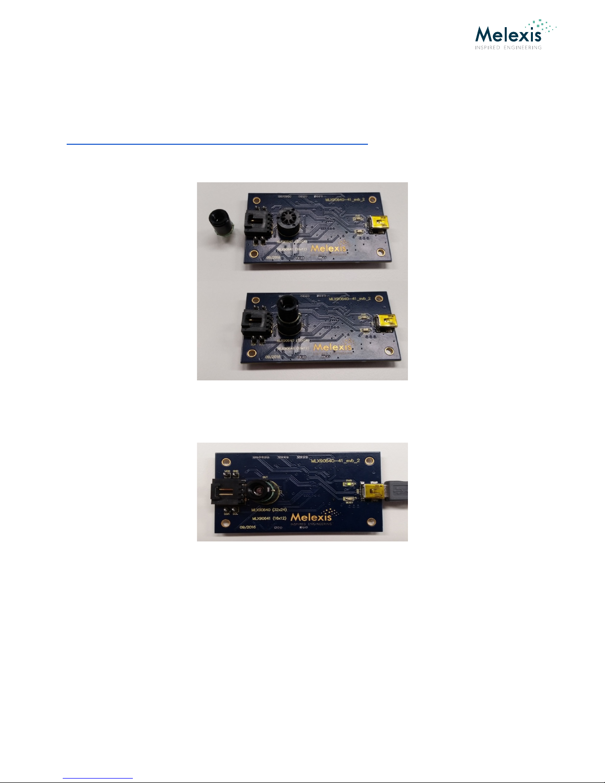
Insert the sensor in the ZIF socket on the PCB. Take care to align the notch with the silk screen on the PCB.
Next, connect the PCB with the USB port of the computer. The computer should indicate that a new USB device
is being installed and indicate after a while it has been installed successfully. This installation normally happens
only once. The pwr LED on the PCB should be on.

EVB90640/1
User manual
Rev. 2 Page 2 of 7
2. Operation
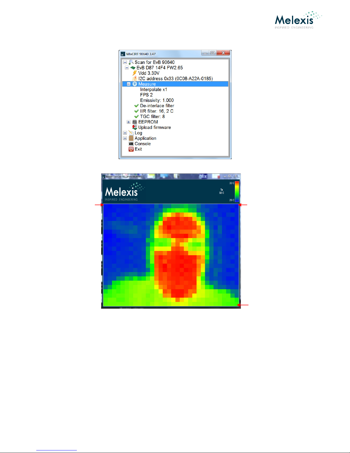
Now start the EVB program. The program will scan for the EVB and you should see a screen as below:
The EVB has been recognized and a sensor has been found on the PCB. The I2C address of the sensor is shown
and its factory ID.
The sensor is powered when the EVB starts. If needed, one can turn off the supply voltage by pressing the Vdd
button .
Now, click on the + in front of the easure tab.
Here one can control by clicking on the item:
•The external bilinear interpolation of the thermal image (x1, x2 or x4);
•The (sub-)frame rate of the sensor: 0.5Hz, 1Hz, 2Hz, 4Hz … 64Hz. Initially, the software reads the frame
rate as set in the EEPRO of the sensor. The factory default is 2Hz;
•The emissivity of the object, to be entered by the user. Standard setting E=1;
•Enable or disable the external de-interlace filter for the LX90640;
•Enable and configure the external IIR small signal filter. There is a value for the depth of the filter (a
higher value reduces noise) and a threshold value, which controls at which object temperature jump the
filter is reset;
•Enable or disable the thermal gradient compensation (TGC) filter and filter depth (minimal 8) (not
advised for LX90640);
EVB90640/1
User manual
Rev. 2 Page 3 of 7
Now double click the measure tab:
The measurement starts and the resulting thermal image is shown in a new screen.
In the top right corner one can see the maximum and minimum temperature of the temperature scale, the
sensor temperature Ta and the temperature To of the pixel at the pointer location.
Note that the button “measure” has changed to “standby”. By clicking this, one can halt the imager.
Pixel 1 Pixel 32
Pixel 768

EVB90640/1
User manual
Rev. 2 Page 4 of 7
In the Application tab one can control the color range of the visualization. This does NOT influence the actual
measurement range. One can also choose the desired temperature unit and mirror the image if needed for
presentation purposes. The restart on full EVB assures that the EVB would restart by itself if the memory of the
EVB would overflow.
In the “Range” tab one can choose between autoscale or set the minimum and maximum temperature manually.
EVB90640/1
User manual
Rev. 2 Page 5 of 7
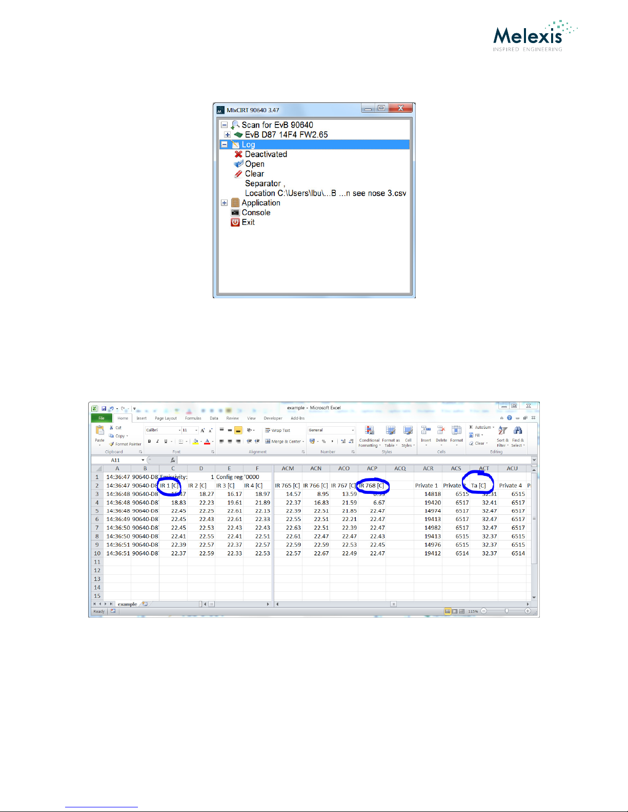
In the log tab, one can control where and if the measured data is stored on the PC. The file can also be opened in
Excel from here.
After measurement of each sub-frame, The data is stored with all measurements of one full frame (768 pixels) in
one line. The next frame is stored on the next line.
Each line starts with a timestamp, followed by the temperature reading of each individual pixel, row by row.
After 768 object temperature readings, follow internal parameters, among which the Ta, which is the sensor
temperature.
The data that is stored is the measurement data AFTER application of the de-interlacing and IIR filter if selected,
but without interpolation.
EVB90640/1
User manual
Rev. 2 Page 6 of 7
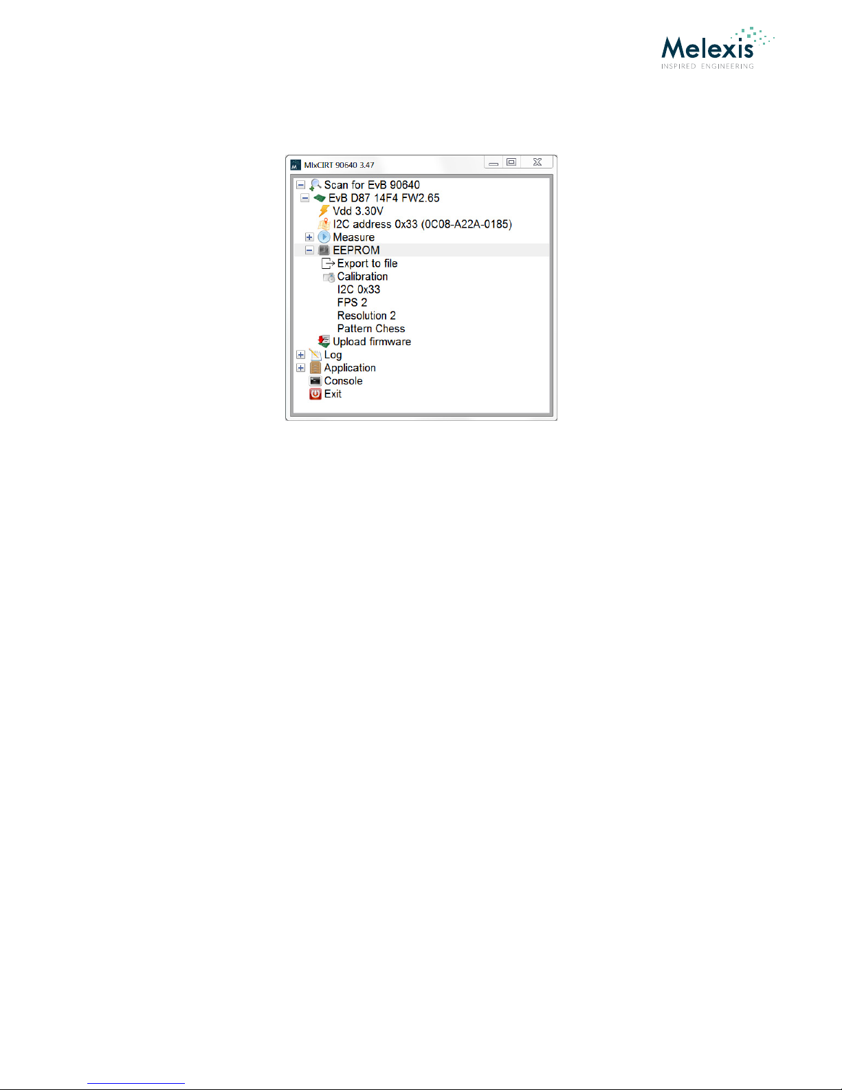
Clicking on the EEPRO tab will show you the EEPRO content. The program also shows what the current
EEPRO content means for FPS, resolution setting and sub-frame pattern. This is the configuration the sensor
will start in after POR.
Under the EEPRO tab there is also a tab to export the EEPRO information to file and a button to upload new
firmware to the EVB if needed. Here is also a tab to point the program to the file directory where a special
calibration file for a specific sensor is located – if available.
3. ESD Precautions
Electronic semiconductor products are sensitive to Electro Static Discharge (ESD).
Always observe Electro Static Discharge control procedures whenever handling semiconductor products.

EVB90640/1
User manual
Rev. 2 Page 7 of 7
4. Disclaimer
The information furnished by Melexis herein (“Information”) is believed to be correct and accurate. Melexis disclaims (i) any and all liability in connection with or arising out of the
furnishing, erformance or use of the technical data or use of the roduct(s) as described herein (“Product”) (ii) any and all liability, including without limitation, s ecial,
consequential or incidental damages, and (iii) any and all warranties, ex ress, statutory, im lied, or by descri tion, including warranties of fitness for articular ur ose, non-
infringement and merchantability. No obligation or liability shall arise or flow out of Melexis’ rendering of technical or other services.
The Information is rovided "as is” and Melexis reserves the right to change the Information at any time and without notice. Therefore, before lacing orders and/or rior to
designing the Product into a system, users or any third arty should obtain the latest version of the relevant information to verify that the information being relied u on is current.
Users or any third arty must further determine the suitability of the Product for its a lication, including the level of reliability required and determine whether it is fit for a
articular ur ose.
The Information is ro rietary and/or confidential information of Melexis and the use thereof or anything described by the Information does not grant, ex licitly or im licitly, to
any arty any atent rights, licenses, or any other intellectual ro erty rights.
This document as well as the Product(s) may be subject to ex ort control regulations. Please be aware that ex ort might require a rior authorization from com etent authorities.
The Product(s) are intended for use in normal commercial a lications. Unless otherwise agreed u on in writing, the Product(s) are not designed, authorized or warranted to be
suitable in a lications requiring extended tem erature range and/or unusual environmental requirements. High reliability a lications, such as medical life-su ort or life-
sustaining equi ment are s ecifically not recommended by Melexis.
The Product(s) may not be used for the following a lications subject to ex ort control regulations: the develo ment, roduction, rocessing, o eration, maintenance, storage,
recognition or roliferation of 1) chemical, biological or nuclear wea ons, or for the develo ment, roduction, maintenance or storage of missiles for such wea ons: 2) civil
firearms, including s are arts or ammunition for such arms; 3) defense related roducts, or other material for military use or for law enforcement; 4) any a lications that, alone
or in combination with other goods, substances or organisms could cause serious harm to ersons or goods and that can be used as a means of violence in an armed conflict or any
similar violent situation.
The Products sold by Melexis are subject to the terms and conditions as s ecified in the Terms of Sale, which can be found at htt s://www.melexis.com/en/legal/terms-and-
conditions.
This document su ersedes and re laces all rior information regarding the Product(s) and/or revious versions of this document.
Melexis NV © - No art of this document may be re roduced without the rior written consent of Melexis. (2016)
ISO/TS 16949 and ISO14001 Certified
Table of contents
Other Melexis Motherboard manuals


